Hướng dẫn sử dụng máy đo độ ồn Testo 815
•
1 like•293 views

Hướng dẫn sử dụng máy đo độ ồn Testo 815 https://testostore.vn/san-pham/may-do-do-on-testo-815/ https://testostore.vn/

Recommended
Recommended
More Related Content
What's hot
What's hot (19)
Similar to Hướng dẫn sử dụng máy đo độ ồn Testo 815
Similar to Hướng dẫn sử dụng máy đo độ ồn Testo 815 (20)
More from Tenmars Việt Nam
More from Tenmars Việt Nam (20)
Recently uploaded
Recently uploaded (20)
Hướng dẫn sử dụng máy đo độ ồn Testo 815
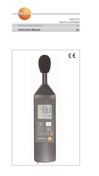
- 1. Bedienungsanleitung de Instruction Manual en testo 815 Sound Level Meter
- 2. 18 General Information General Information Please read this documentation through carefully and familiarise yourself with the operation of the product before putting it to use. Keep this document to hand so that you can refer to it when necessary Identification Symbol Meaning Comments Warning advice: Warning! Read the warning advice Serious physical injury could be caused if the carefully and take the specified precautionary measures are specified precautionary not taken. measures Warning advice: Caution! Read the warning advice Slight physical injury or damage to equipment carefully and take the could occur if the specified precautionary specified precautionary measures are not taken. measures Important Please pay particular attention. Key Press the key. Text, Display contents Text or symbol is shown on the display. Taste
- 3. 19Contents en Contents General Information ........................................................18 Contents ........................................................................19 1. Safety Advice..................................................................20 2. Intended Purpose ..........................................................21 3. Product Description........................................................22 3.1 Display and operating elements ........................................................22 3.2 Supply voltage ..................................................................................22 4. Initial Operation ..............................................................23 4.1 Putting in the battery ........................................................................23 5. Operation ......................................................................23 5.1 Switching on/off ................................................................................23 5.2 Setting the meter ..............................................................................23 5.3 Measuring ........................................................................................26 5.4 Calibration ........................................................................................28 6. Care and Maintenance....................................................29 6.1 Changing the battery ........................................................................29 6.2 Microphone ......................................................................................29 6.3 Meter ................................................................................................29 7. Technical Data ................................................................30 8. Accessories and Spare Parts..........................................31 9. Measurement Engineering Fundamentals........................32
- 4. 20 1. Safety Advice 1. Safety Advice Avoid electrical hazards: Never use to measure on or near live parts! Product safety/preserving warranty claims: Operate the meter only within the parameters specified in the technical data. Do not use force. Never store with solvents (e.g. acetone). Observe maximum storage and transport temperature as well as operating temperature. Ensure that liquid does not enter into the microphone. Open the meter only when this is expressly described in the Instruction Manual for maintenance purposes. Carry out only the maintenance and repair work that is described in the Instruction Manual. Follow the prescribed steps exactly. For safety reasons, use only original spare parts from Testo. Warranty claims will no longer apply if the meter is handled improperly or force is applied. Ensure correct disposal: Dispose of defective rechargeable batteries and spent batteries at the collection points provided. Send the meter directly to us at the end of its life cycle. We will ensure that it is disposed of in an environmentally friendly manner. As declared in the certificate of conformity, this product fulfils the guidelines of 89/336/EEC. Meter conforms with DIN EN 60651, (IEC 651), Class 2
- 5. 212. Intended Purpose en 2. Intended Purpose testo 815 is a sound meter the sound level measurement ranges 32-80dB, 50-100dB and 80-130dB, two time weightings, two frequency weightings, a maximum/minimum function and a tripod screw. Using the calibrator (accessory), the meter can be recalibrated with the enclosed adjustment screwdriver.
- 6. 22 3. Product Description 3. Product Description 3.1 Display and operating elements 3.2 Supply voltage Voltage is supplied by a 9V block battery Type 006 P or IEC6F22 or NEDA 1604 (included). On/Off button Fast/Slow button Display Min/Max button A/C weighting Level button Battery compartment (rear) Calibration screw Microphone Tripod thread
- 7. 23 4. Initial Operation 4.1 Putting in the battery 1 Open back of testo 815 using a screwdriver and remove cover. 2 The battery compartment is located in the cover. 3 Lift the holding clip for the battery slightly, remove battery. 4 Put in new 9 Volt block battery. Ensure +/- is correct. 5 Put the cover back on the housing and close using a screwdriver. 5. Operation 5.1 Switching on/off Switch on meter: press . - All segments light up briefly and the meter switches to the measurement mode (measurement range 32 - 80dB). Switch off meter: press . 5.2 Setting the meter The following functions can be set: Function Description Setting options Time weighting Sets measurement time Fast or Slow Frequency weighting Sets weighting, A or C Level Switches over 32 to 80dB measurement range 50 to100dB 80 to 130dB Hold function Switches on MAX / MIN Max Hold/Min Hold Function 4. Initial Operation en
- 8. 24 Setting the time weighting The measurement time (time weighting) is set by pressing . SLOW/FAST: The ranges "Slow" with a time weighting of 1s and "Fast" with a time weighting of 125ms are available. Incoming sound signals are integrated in a time period from 1s or 125ms respectively. When "Fast" is set, the display rate of a reading increases to approx. 5-6 measurement rates per second. The "Slow" time weighting is selected for noises whose signals only change slowly e.g. machines, photocopiers, printers etc. Select the "Fast" mode to measure sudden changes in sound level (e.g.building machines). Setting the frequency weighting Frequency weighting is set with the button. A/C: The frequency weightings "A" and "C" are available. Frequency weighting A is used for standard sound level measurements. This weighting corresponds to the sound pressure felt by the human ear, also referred to as "aurally compensated sound level". If the low frequency levels of a sound are to be assessed, frequency weighting C is used. If the displayed value is considerably higher during the C weighting than during the A weighting, the level of low frequency noise is high. 5. Operation
- 9. 25 Setting the measurement range The measurement range is switched using the button. Level: The testo 815 sound level meter covers the range 32 to 130 dB. The measurement ranges 32 to 80, 50 to 100 and 80 to 130 dB are available. The meter is in the lowest measurement range 32 to 80 dB when first switched on. The measurement range is switched each time to a higher level by activating the "LEVEL" button. You can switch back into the lowest range 32 to 80 dB from the highest range 80 to 130 dB. MAX/MIN - Hold Function Use the button to activate the Max Hold or Min Hold function. "Max" appears in the display once the "Max/Min" button is activated. In this mode, the meter shows the maximum value of the sound level since the max mode was set. The display is only updated if a higher value than the previously displayed value is measured. The meter goes into the Min-Hold mode when the "Max/Min" button is activated again. "Min" appears in the display. The display is only updated if the sound level is below the displayed value. Max/Min flashes in the display if the "Max/ Min" button is activated again. The current value is displayed and the maximum or minimum value is stored in this mode. The maximum or minimum value is displayed by again activating the "Max Min" button. The "Max Min" button must be kept pressed for two seconds in order to quit the Max Min mode. The Max-Min mode is cancelled by activating the Level, Fast/Slow or A/C button. 5. Operation en
- 10. 26 5.3 Measuring Sound waves can be reflected off walls, ceilings and other objects. Also the meter housing and the person measuring (if measuring incorrectly) are disturbing factors in the sound field and can lead to incorrect measurement results. How to avoid measurement errors The meter housing and the person operating the meter may not only obstruct the sound coming from a certain direction but they can also produce reflections and consequently serious measurement errors. Experiments have shown, for example, that the body can cause errors of up to 6 dB with frequencies of 400 Hz if a measurement takes place less than one meter away from the person. This error is less for other frequencies but a minimum distance should be adhered to. Generally, it is recommended that the meter is held at least 30 cm - even better 50 cm - away from the body. We recommend fitting the instrument to a tripod for exact measurements. Measuring 1 Switch on instrument 2 Set measurement time (”FAST/SLOW”) 3 Set frequency (”A/C”) 4 Set measurement range (”Level”) 5 Always direct the microphone exactly at the sound source to be measured (reference direction). 6 Save the highest and lowest value via ”Max/Min” 5. Operation
- 11. 27 Absolute pressure dependency testo 815 is calibrated by default for measurements at a height of 0 m above sea level. Measurements at other heights give rise to measurement errors which can be corrected using a table (see technical data). Subtract the appropriate offset value from the value measured (e.g. - 0.1 dB for measurements at a height of 500 m above sea level). You can avoid this measurement error by calibrating the meter in the corresponding height prior to every measurement. Please refer to the Instruction Manual for the calibrator. Wind cap Generally the wind cap supplied should be attached during measurements outdoors and when air movements occur. Wind noises in the microphone cause measurement errors since the wanted signal (of the noise source) and the wind noise add up together. The wind cap does not falsify the measurement result. Overmodulation and undermodulation With every measurement cycle, the sound level meter checks whether the measured sound level is in the validity range of the respective measurement range. Deviations are indicated by "Over" and "Under" on the display. However, the criteria for overmodulation and undermodulation are different. Overmodulation is signalled if the maximum value (peak value e.g. short sound pulse, bang) during the last measurement cycle was too high. This value may be considerably higher than the actual value of the sound level displayed. Therefore, it can happen that "Over" is signalled although a sound level within the normal framework of the respective measurement range is shown. By contrast "Under" is geared to the measured actual value and is therefore set when the lower limit of the measurement range is reached. 5. Operation en
- 12. 28 5.4 Calibration The testo 815 sound level meter has already been calibrated in the factory. In order to check accuracy, recalibration with the calibrator is recommended particularly if the instrument has not been used for a long period of time. The testo 815 meter should also be checked with the calibrator prior to and following measurements in tough conditions, at great heights, at high air humidity levels or when particularly high demands are made on the measurement results. For calibration purposes, the calibrator is placed with a rotary motion on the microphone. Switch on the sound level meter and set it to the measurement range 50-100 dB, time weighting "Fast" and frequency weighting "A". The calibrator is then switched on by moving the switch to the middle position (94 dB). If the sound level meter deviates from the value shown, it can be readjusted using the adjustment screwdriver supplied. You can then check whether the second level of the calibrator is also within the error limit of ± 0.2 dB. Please note that to do this you must select the corresponding measurement range (80-130 dB). If the value shown is not within the error limit, please contact our service department. 5. Operation
- 13. 29 6. Care and Maintenance 6.1 Changing the battery If the battery symbol appears in the display, the lifetime remaining is approx. 10 hours. To avoid mismeasurement, please change the battery as soon as possible. 1 Unscrew the screw at the back of the testo 815 with a screwdriver and remove the back of the housing. 2 The battery compartment is located at the back of the housing. 3 Remove spent battery and insert new battery, Type 9V Block (observe +/-). 4 Replace back of housing and screw in carefully using screwdriver. 6.2 Microphone A robust, long-term stable measurement microphone is located in the housing head. A function test can be carried out with the calibrator. The housing can be cleaned with alcohol (isopropanol). Please ensure that liquid does not get into the microphone. The attached wind cap also protects the microphone from dust and humidity. Please contact our service department if the microphone is defect. 6.3 Meter testo 815 is maintenance-free and is therefore not bound by any maintenance intervals. Clean the housing with a damp cloth. Weak household cleaning agents can be used. Never clean with abrasive cleaning agents or solutions. 6. Care and Maintenance en
- 14. 30 7. Technical Data Feature Values Sensor: ½ inch electret condenser measurement microphone Overall measurement range: 32 to 130 dB Level ranges: 32 to 80 dB 50 to 100 dB 80 to130 dB Frequency range: 31.5 Hz to 8 kHz Frequency weighting: A/C Reference frequency: 1000 Hz Backup impedance of microphone: 1 kΩ at 1 kHz Absolute pressure dependency: -1.6*10-3 dB/hPa Time weighting: 125 ms (Fast) or 1 s (Slow) Accuracy: ± 1.0 dB (under reference conditions : 94dB at 1kHz) Display: 4 digit LCD display, 13mm high Resolution: 0.1 dB Display update: 0.5 s Battery: 9V Block (6F 22) Battery life: Approx. 70 hours (alkaline manganese) Tripod thread: ¼ inch Operating temperature: 0 to +40°C Operating humidity: 10 to 90 %RH Storage temperature: -10 to +60°C Storage humidity: 10 to 75 %RH Housing material: ABS Absolute pressure dependancy Altitude in metres above s.l. Pressure p in mbar Correction in dB 0 - 250 1013 - 984 0.0 >250 - 850 983 - 915 -0.1 >850 - 1450 914 - 853 -0.2 >1450 - 2000 852 - 795 -0.3 Temperature correction value table Relative humidity: 65 %RH Reference value sound pressure level: 124 dB Temperature range with discrepancy <0.5 dB: 10...40 °C Temperature in °C Correction in dB -10 -0.7 50 1 7. Technical Data
- 15. 31 Frequency weighting Nom. frequency in Hz A-weighting C-weighting Error limits in Hz in dB in dB Class 2 in dB 31.5 -39.4 -3.0 ±3 63 -26.2 -0.8 ±2 125 -16.1 -0.2 ±1.5 250 -8.6 -0.0 ±1.5 500 -3.2 -0.0 ±1.5 1000 0 0 ±1.5 2000 +1.2 -0.2 ±2 4000 +1.0 -0.8 ±3 8000 -1.1 -3.0 ±5 8. Accessories and Spare Parts Name Item no. testo 815 sound level meter 0563 8155 incl. battery, Instruction Manual, screwdriver, wind cap Calibrator 0554 0452 Wind cap 0193 0815 9V rechargeable battery 0515 0025 Recharger for external recharging of rechargeable battery 0554 0025 Screwdriver 0554 0818 7. Technical Data en
- 16. 32 9. Measurement Engineering Fundamentals Pressure and Sound Noises are changes in the sound pressure in the air. When conditions are normal, the air pressure is 1013 mbar about which the sound pressure of the noise source fluctuates. The human ear senses these pressure fluctuations and converts them to nerve pulses. The ear is like a pressure sensor with an enormous dynamic range. The quietest noise which can be heard by humans causes pressure fluctuations of 0.0002 µbar (corresponding to 0 dB), the loudest noise (which can be heard without pain) has a sound pressure level of 635 µbar (corresponding to 130 dB). This corresponds to a pressure difference of around 3,000,000- fold. Since stating the pressure in mbar would result in very long figures, logarithmic notation is used and calculation is with level values. In this way, a level increase of 20 dB corresponds to a 10- fold increase in pressure. A sound level meter to EN 60651 measures the frequency weighted actual value of the sound level, it is a measure of the total sound energy converted during measurement time. 9. Measurement Engineering Fundamentals
- 17. 33Notes en
- 18. Notes34
- 19. Notes 35
- 20. testo AG Postfach 1140, 79849 Lenzkirch Testo-Straße 1, 79853 Lenzkirch Telefon: (07653) 681-0 Fax: (07653) 681-100 E-Mail: info@testo.de Internet: http://www.testo.com 0973.8150/03/C/wh/04.05.2006