Hướng dẫn sử dụng bộ kiểm tra mạng Extech 40180
•
0 likes•45 views

This document provides instructions for using a tone generator and amplifier probe device. It can be used to trace cables and wires by connecting the tone generator to one end of a cable and using the probe to detect the tone and identify the wire. The device can also test telephone cables and lines to check polarity, continuity, and line conditions. Basic operation involves switching the tone generator on and using the probe to pick up the signal on the wire being tested. The guide describes setup and use for various wire and cable testing applications.

Recommended
More Related Content
What's hot
What's hot (15)
Similar to Hướng dẫn sử dụng bộ kiểm tra mạng Extech 40180
Similar to Hướng dẫn sử dụng bộ kiểm tra mạng Extech 40180 (20)
More from Tenmars Việt Nam
More from Tenmars Việt Nam (20)
Recently uploaded
Recently uploaded (20)
Hướng dẫn sử dụng bộ kiểm tra mạng Extech 40180
- 1. User's Guide Tone Generator and Amplifier Probe Model 40180
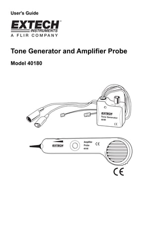
- 2. 40180-EU-EN-V2.4-4/122 Introduction Congratulations on your purchase of Extech’s Model 40180. This tone generator and amplifier probe set is used to quickly trace and identify cables or wires within a group and also check the operation of phone lines. With proper use and care, this meter will provide many years of reliable service. Meter Description 1. Power switch 2. Modular connectors 3. Test leads 4. Battery compartment (rear) 5. Probe tip 6. Volume/Sensitivity control 7. Power button 8. Battery compartment (rear) 9. Headphone jack 1 2 3 4 5 6 7 8 9
- 3. 40180-EU-EN-V2.4-4/123 Operating Instructions Note: Remember to turn off the tone generator after tracing the cables Cable/Wire tracing CAUTION: Do not connect the tone generator in the TONE position to any wire or cable with an active circuit of more than 24VAC. 1. Connect the tone generator to the cable a) For cables terminated at one end, connect the red alligator clip to a wire and the black alligator clip to equipment ground b) For unterminated cables, connect the red alligator clip to one wire and the black alligator clip to another wire. c) For cables with modular connectors, plug the RJ11 or RJ45 connectors directly into the mating cable connectors. 2. Set the tone generator power switch to the TONE position. 3. On the amplifier probe, press and hold the side on/off switch. 4. Hold the insulated probe tip against the wire in question to pick up the signal generated by the tone generator. 5. Rotate the volume/sensitivity control on the top of the probe for the appropriate level and sensitivity to identify and trace the wire. 6. The tone will be the loudest on the wires connected to the tone generator. Note: RJ11 tests are performed on one pair only and RJ45 tests are performed on pins 4 and 5. Note: A headphone jack is located on the bottom of the probe. Identifying telephone cable Tip and Ring – Using Alligator Clips 1. Switch the tone generator to the OFF position 2. Connect the red test lead to one line and the black lead to the other line. 3. The LED color indicates the connection to the RED test lead as: 4. GREEN = Ring side, RED = Tip side. Identifying telephone cable Tip and Ring – Using the RJ-11 or RJ-45 Connectors 1. Switch the tone generator to the OFF position 2. Connect the RJ-11 or RJ-45 connector mating cable connector. 3. The LED color indicates the condition of the telephone jack wiring. GREEN = Jack wired properly, RED = Jack wired with reversed polarity. Identifying telephone cable Line Condition 1. Switch the tone generator to the OFF position 2. Connect the red test lead to the RING side and the black test lead to the TIP side. 3. The LED will indicate line condition by: GREEN = CLEAR , OFF = BUSY, Flickering YELLOW = RINGING 4. Switch the tone generator power switch to CONT to terminate the call.
- 4. 40180-EU-EN-V2.4-4/124 Continuity testing CAUTION: Do not connect the tone generator in the CONT position to any wire or cable with an active circuit. 1. Connect the test leads to the wire pair under test. 2. Switch the tone generator to the CONT position. 3. The LED will glow bright GREEN for a low resistance or continuity. The LED will glow less brightly as the resistance increases and will extinguish at approximately 10,000 ohms. Tone selection The output of the tone generator can be set to continuous or wobble. To change the type of output, change the tone type switch position (located in the battery compartment) Battery replacement Install a new battery by removing the battery cover as indicated in the meter description diagram. You, as the end user, are legally bound (Battery ordinance) to return all used batteries and accumulators; disposal in the household garbage is prohibited! You can hand over your used batteries / accumulators at collection points in your community or wherever batteries / accumulators are sold! Disposal: Follow the valid legal stipulations in respect of the disposal of the device at the end of its lifecycle Specifications Power 9V battery (tone generator and probe (1 each)) Tone output 1kHz, 6V square wave (approximately) Dimensions Probe: 228 x 57 x 25.4mm (9 x 2.25 x 1”) Generator: 63.5 x 63.5 x 38.1mm (2.5 x 2.5 x 1.5”) Weight 272g (0.6lb) Copyright © 2012 Extech Instruments Corporation (a FLIR company) All rights reserved including the right of reproduction in whole or in part in any form. www.extech.com