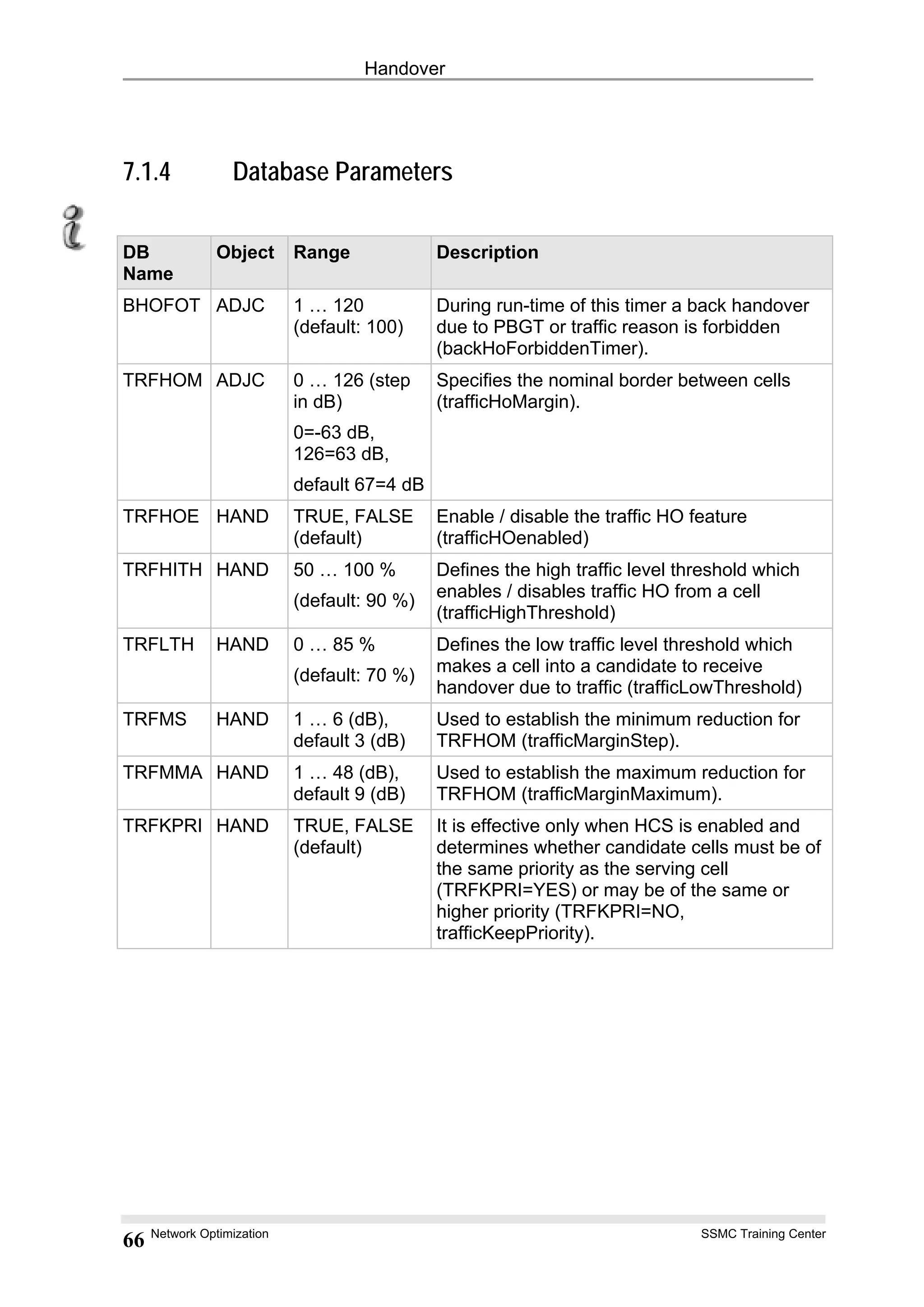
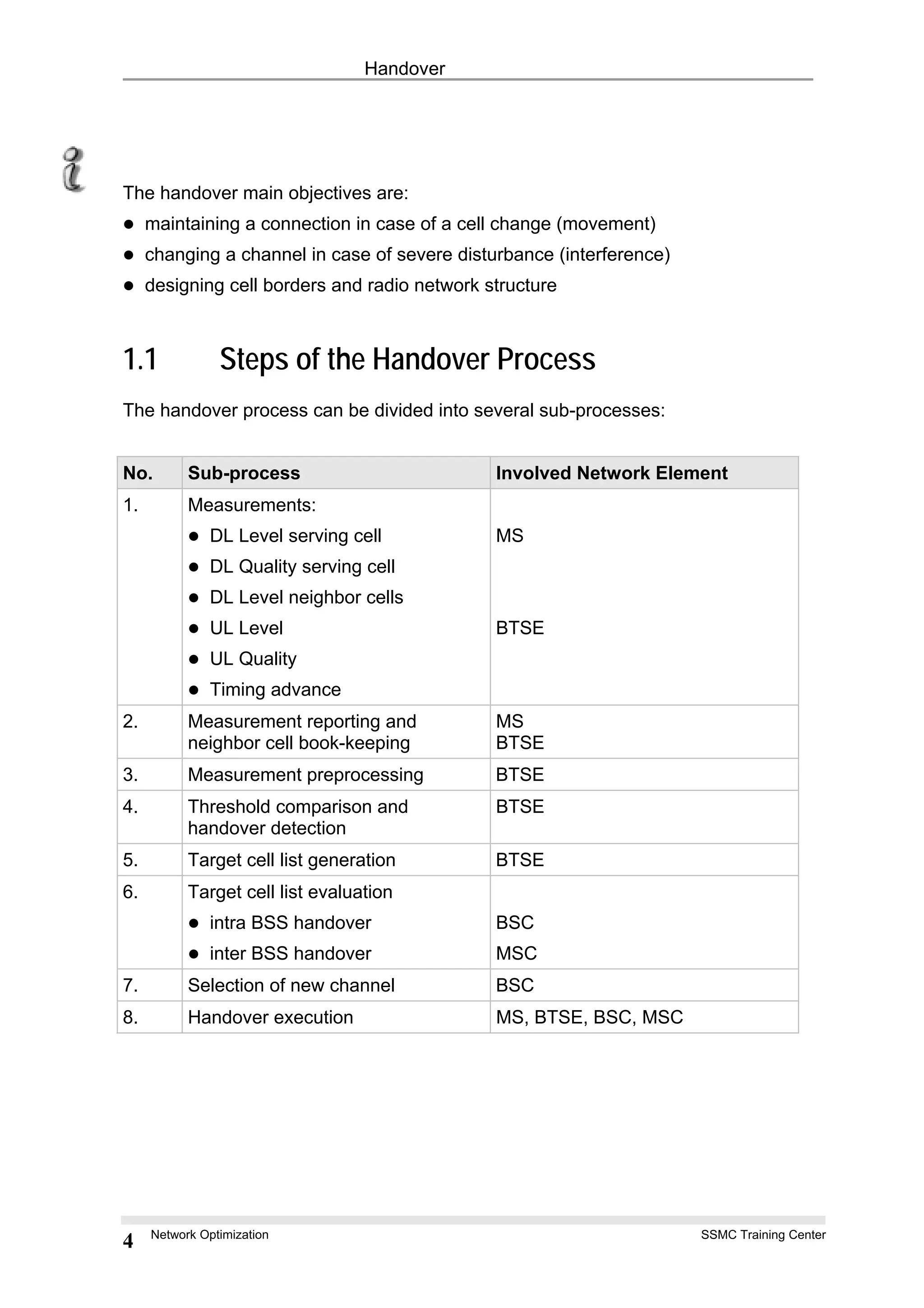
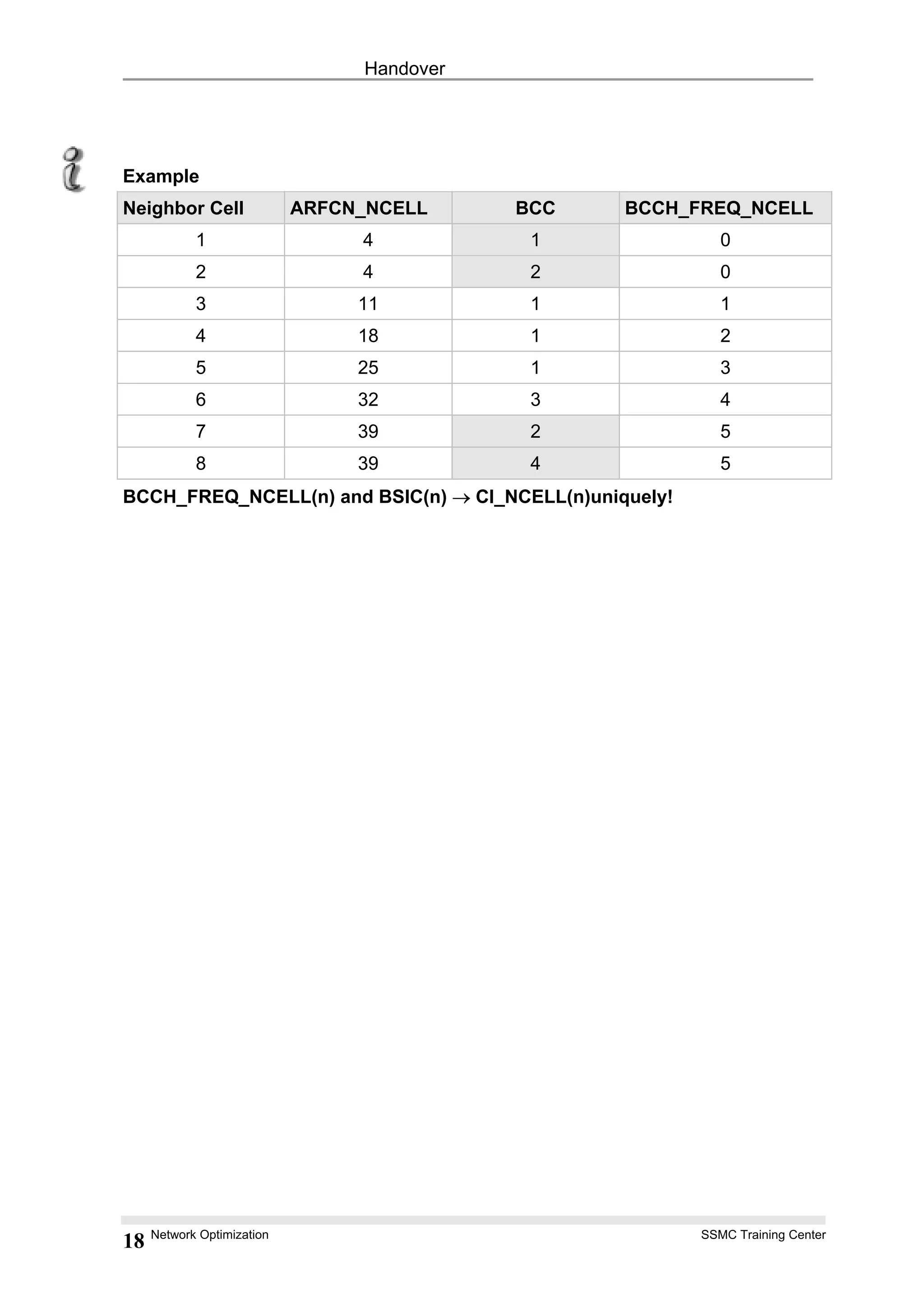
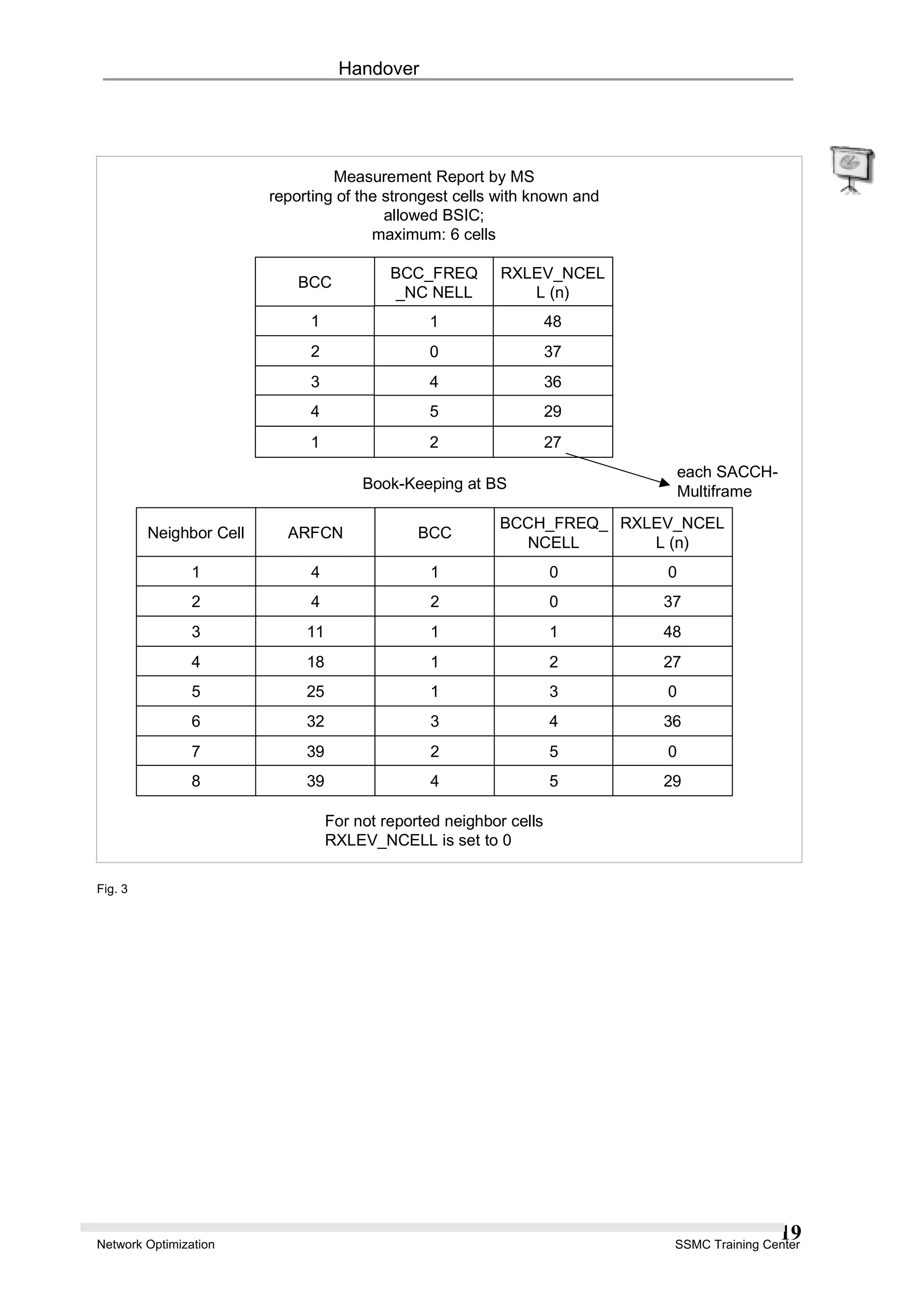
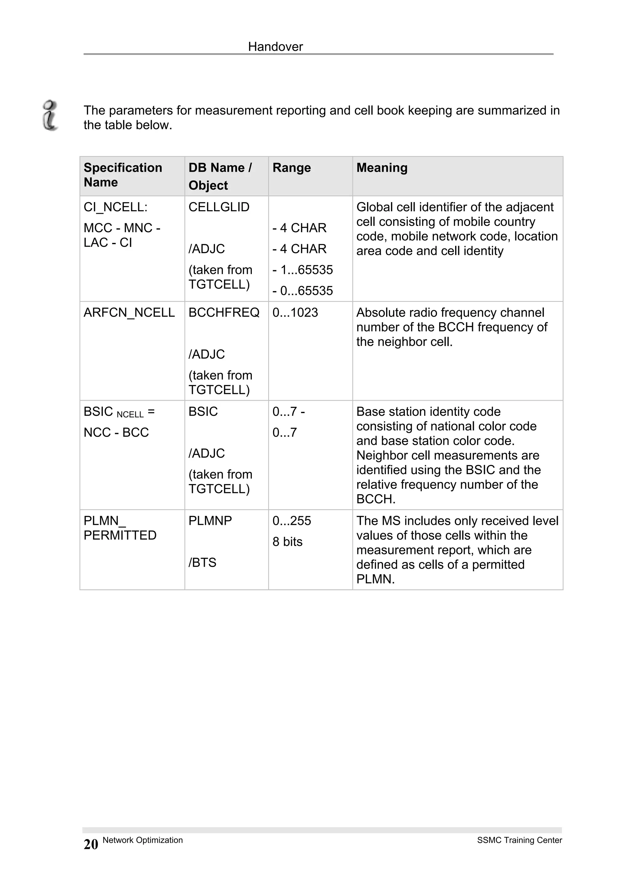
The MS measures signal levels and quality on neighboring cells and reports these measurements along with cell identities to the serving base station. The base station maintains a book-keeping table of these measurements to track neighboring cells for each MS. This information is used to determine candidate cells and trigger handovers when thresholds are met.

![Handover
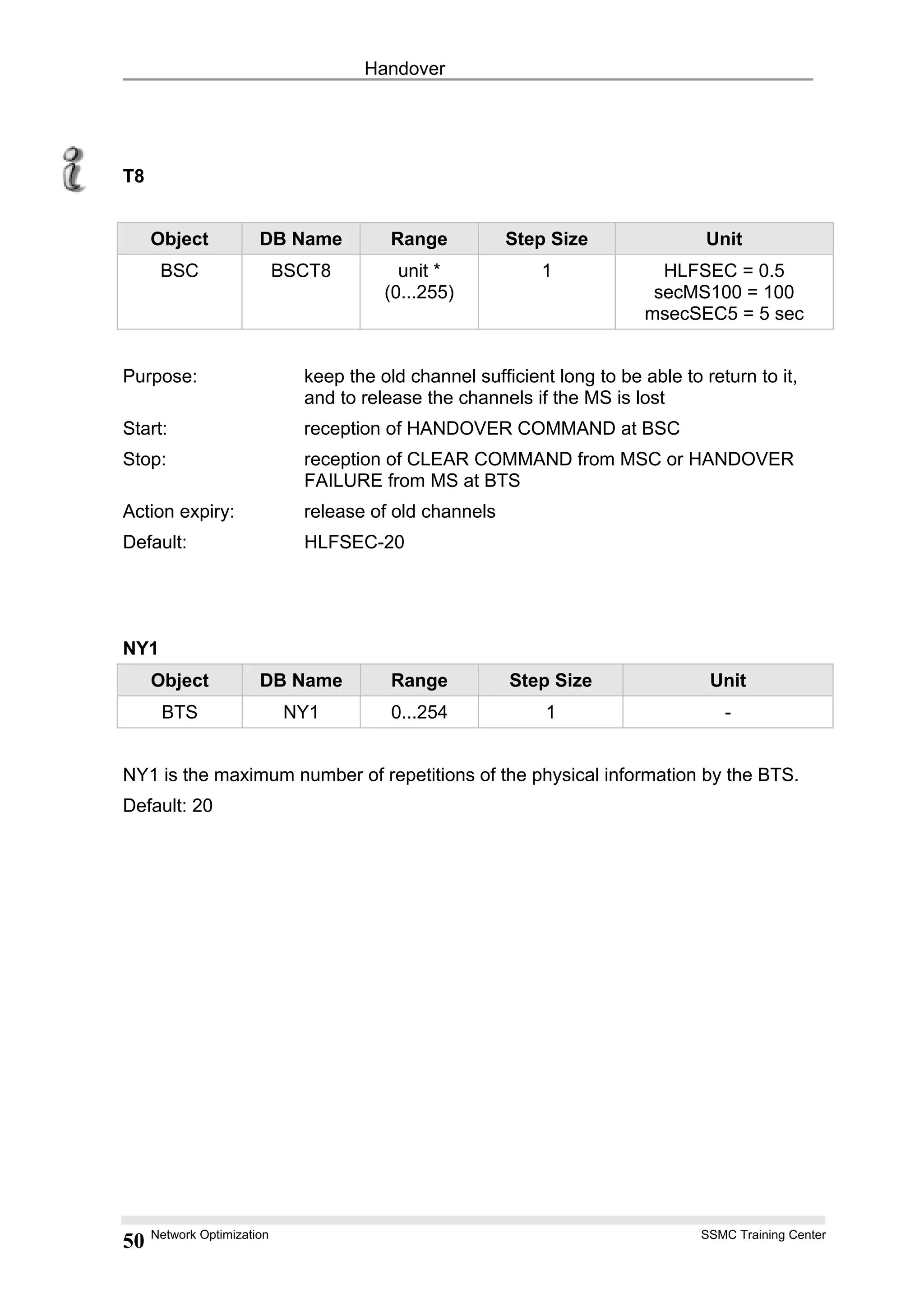
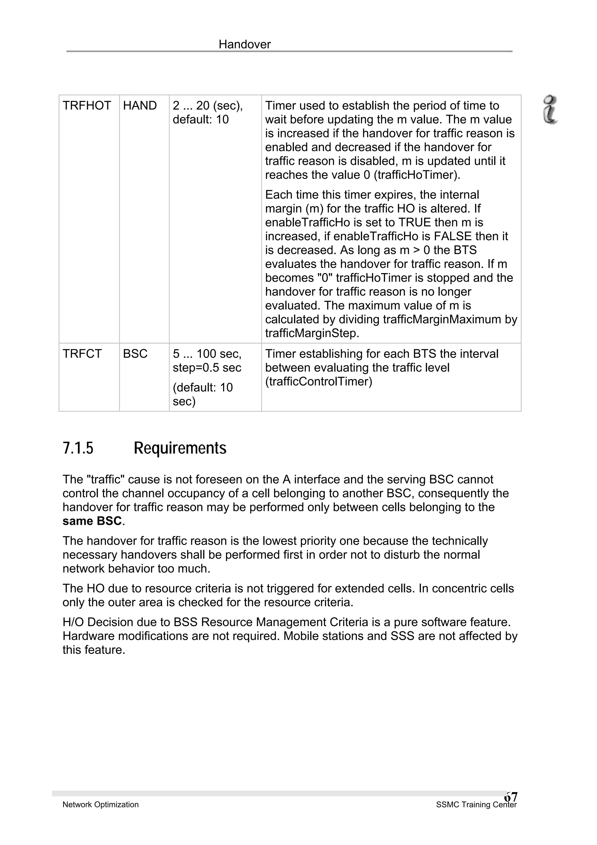
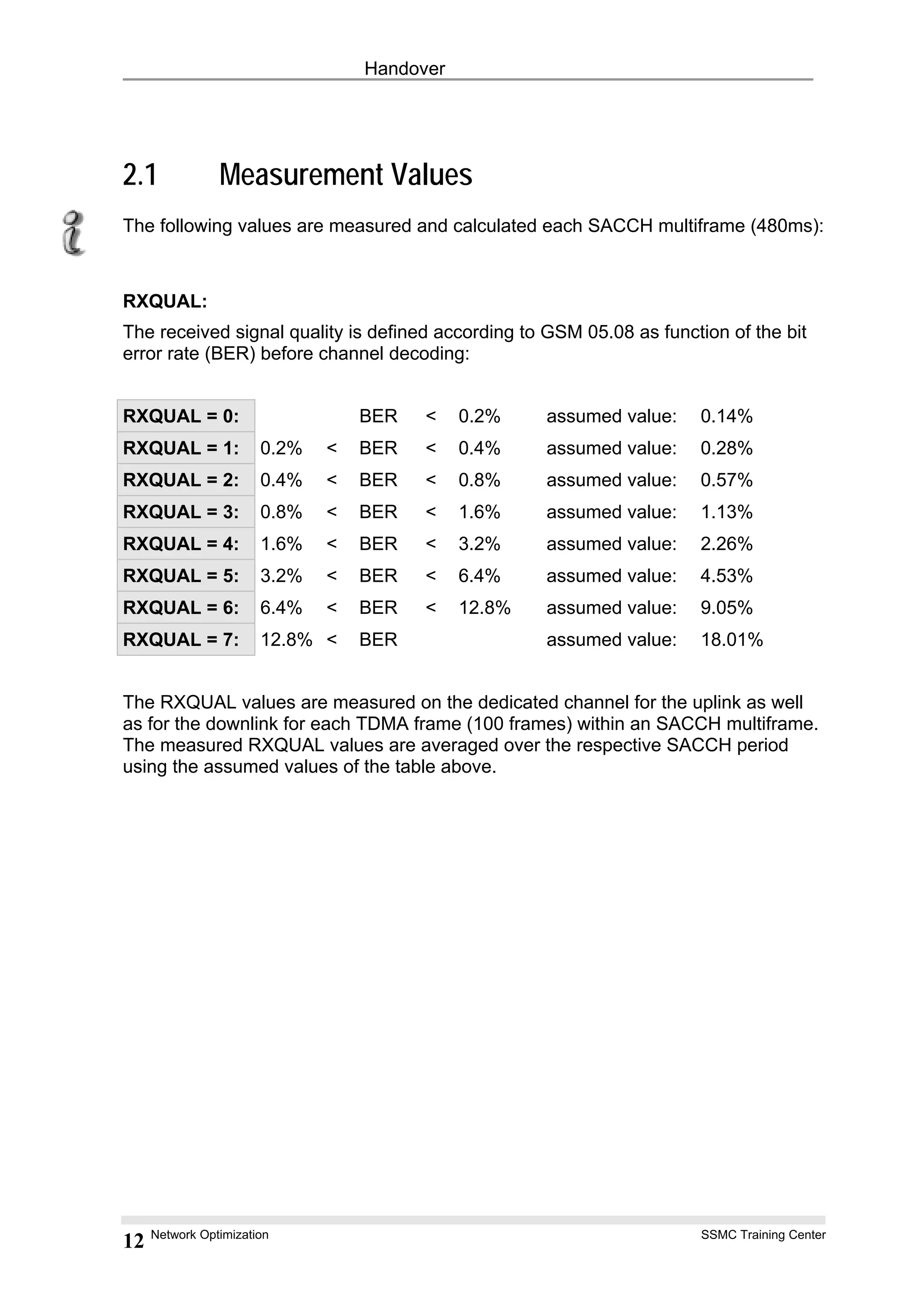
RXLEV:
The received signal level is measured on the dedicated channel for the uplink as well
as for the downlink for each TDMA frame (100 frames) within an SACCH multiframe.
The measured level values in [dBm] are averaged over the respective SACCH
period. The average value is mapped on an RXLEV value (refer to GSM 05.08):
RXLEV = 0: < -110 dBm
RXLEV = 1: -110 dBm ... -109 dBm
RXLEV = 2: -109 dBm ... -108 dBm
... ...
RXLEV = 62: -49 dBm ...-48 dBm
RXLEV = 63: > -48 dBm
RXLEV_NCELL(n):
The mobile measures the level received on the BCCH frequency of each neighbor
cell n. The mapping is as for RXLEV.
MS_BS_DIST:
The distance MS_BS_DIST between the MS and BS is calculated from the timing
advance (TA) value measured by the BS and is coded as follows:
MS_BS_DIST = 0, 1, ... 35. Distance[Km]
Network Optimization SSMC Training Center
14](https://image.slidesharecdn.com/05-handover-150329053559-conversion-gate01/75/05-handover-14-2048.jpg)

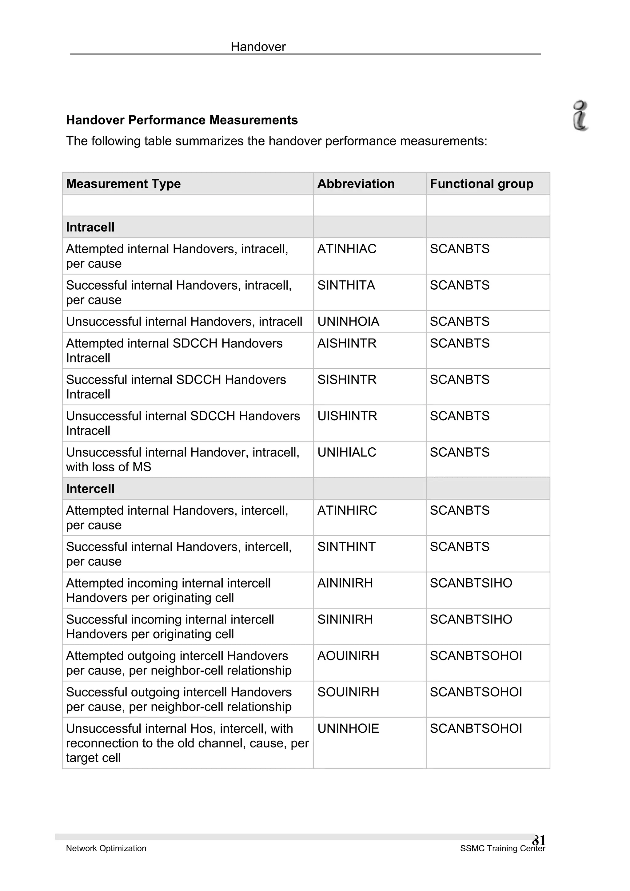
![Handover
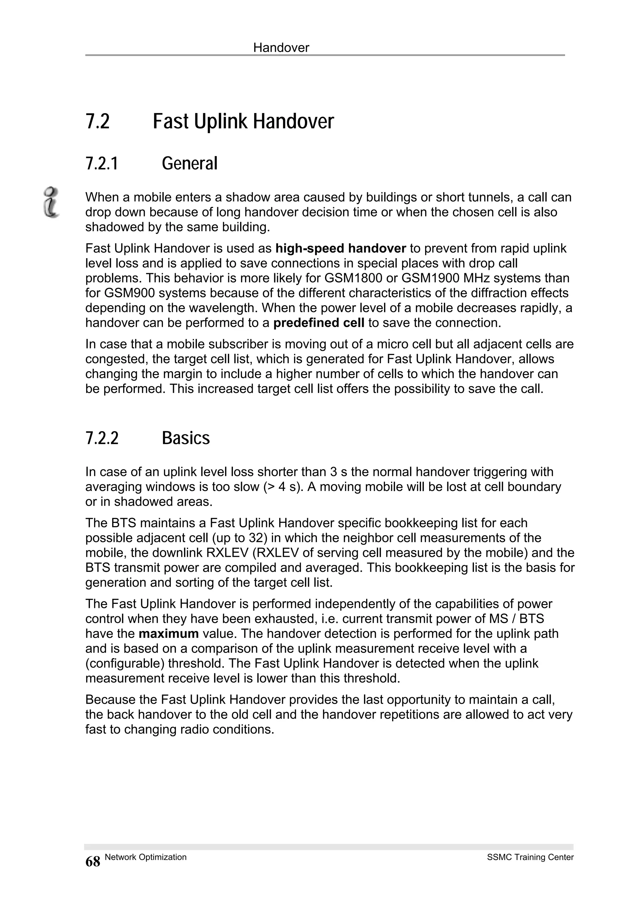
3.1 Decision Criteria
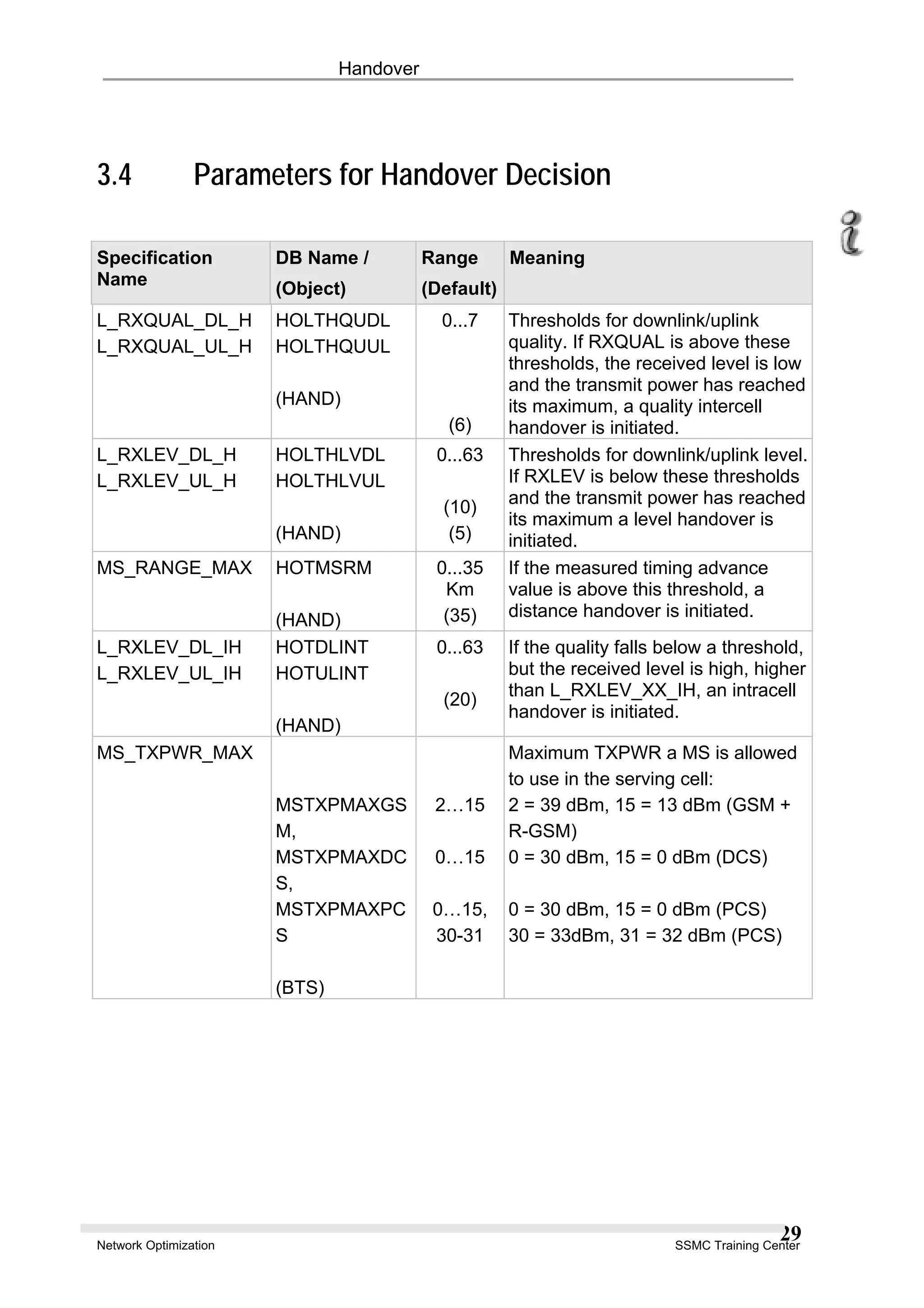
The standard handover algorithm for radio criteria uses the decision criteria listed in
the table below.
These criteria will be modified for a speed sensitive handover used within hierarchical
cells.
Handover Types Decision Criteria
Intercell HO due to Quality 1. RXQUAL_XX > L_RXQUAL_XX_H
2. RXLEV_XX < L_RXLEV_XX_IH
3. XX_TXPWR = Min (XX_TXPWR_MAX, P)
HO due to Level 1. RXLEV_XX < L_RXLEV_XX_H
2. XX_TXPWR = Min (XX_TXPWR_MAX, P)
HO due to Distance 1. MS_BS_DIST > MS_RANGE_MAX
HO due to Power Budget 1. RXLEV_NCELL(n) > RXLEV_MIN(n) + Max
(0, MS_TXPWR_MAX(n) - P)
2. PBGT(n) > HO_MARGIN(n)
Intracell HO due to Quality 1. RXQUAL_XX > L_RXQUAL_XX_H
2. RXLEV_XX > L_RXLEV_XX_IH
Notes:
XX: used as variable for both UL (uplink) and DL (downlink)
MS_TXPWR_MAX: maximum allowed transmit power of the MS in the serving
cell,
MS_TXPWR_MAX(n): maximum allowed transmit power of the MS in the
adjacent cell “n“
P [dBm]: the maximum power capability of the MS (power class)
An intercell handover due quality or level is only performed if the transmit power of
the MS or BS respectively is on its maximum
Network Optimization SSMC Training Center
26](https://image.slidesharecdn.com/05-handover-150329053559-conversion-gate01/75/05-handover-26-2048.jpg)
![Handover
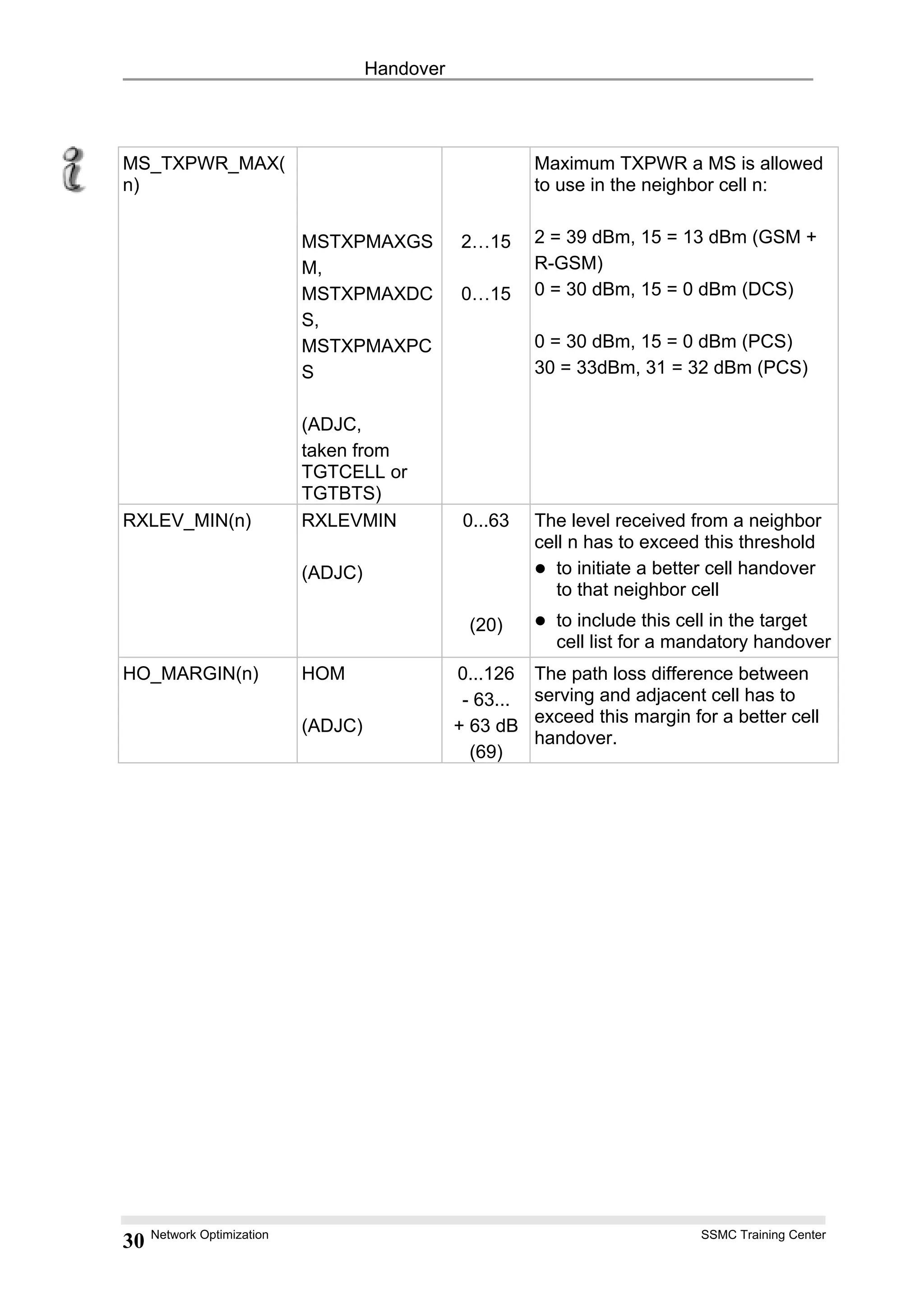
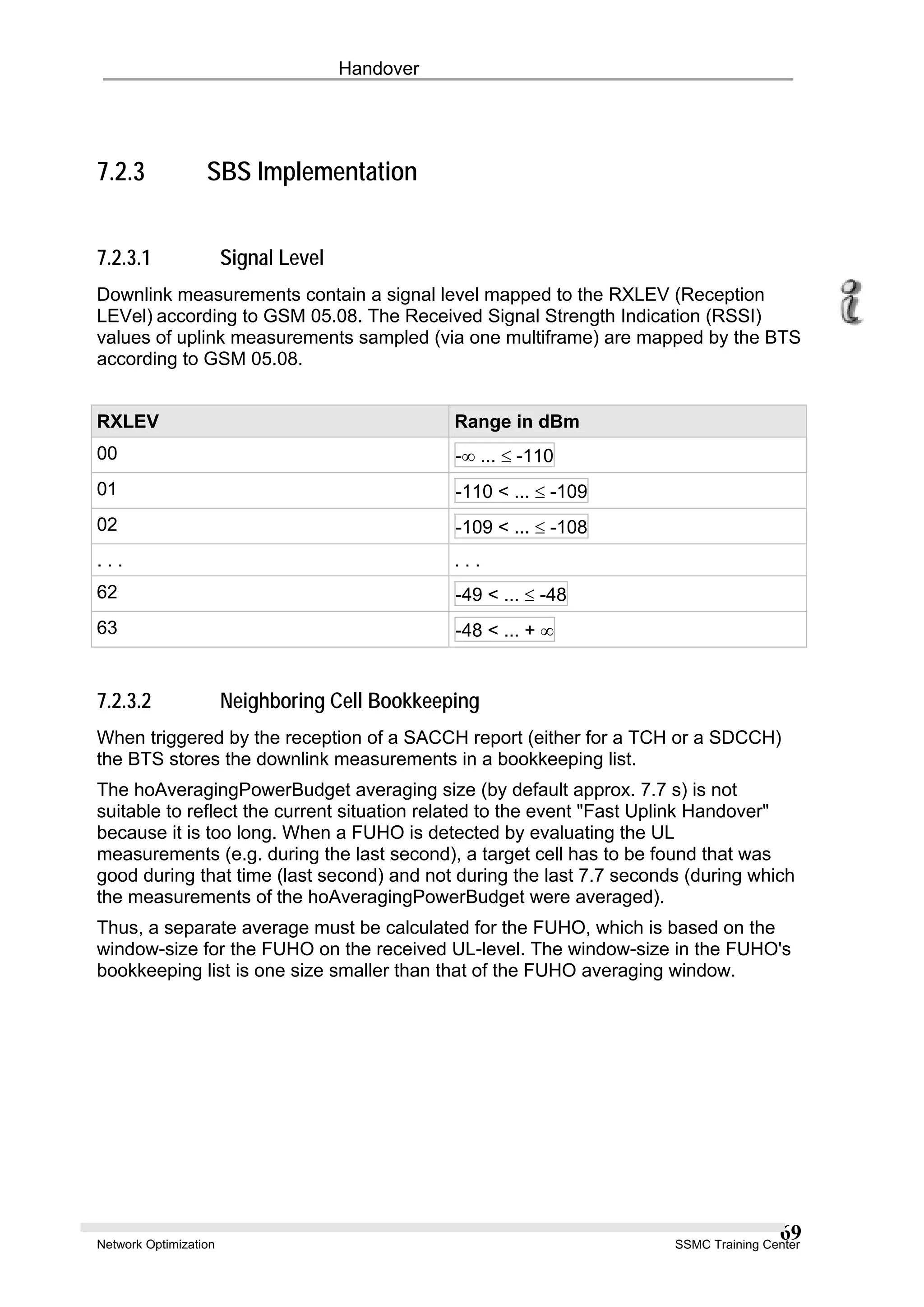
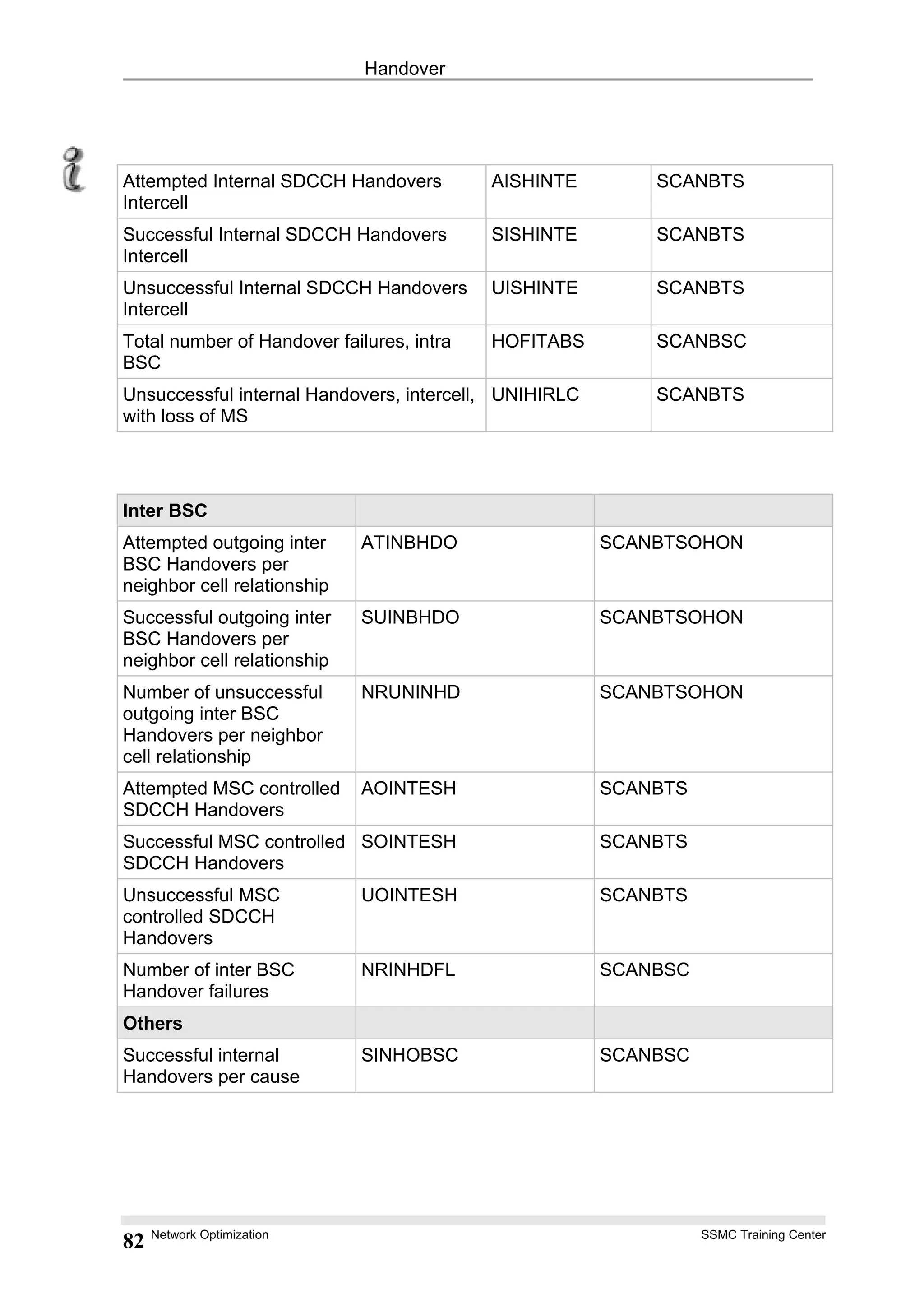
3.3 Power Budget
The power budget PBGT(n) is calculated in the following way:
PBGT(n) = RXLEV_NCELL(n) - (RXLEV_DL + PWR_C_D)
+ Min(MS_TXPWR_MAX, P) - Min(MS_TXPWR_MAX(n), P)
RXLEV_DL: averaged value of the measured downlink level in the serving
cell,
PWR_C_D: BS_TXPWR_MAX [dBm] - BS_TXPWR [dBm]
averaged difference between the maximum downlink RF power
BS_TXPWR_MAX and the actual downlink power BS_TXPWR
due to power control in the serving cell.
RXLEV_NCELL(n): averaged value of the measured downlink level of the adjacent
cell “n”
HO_MARGIN(n): handover margin; if path loss with respect to the serving cell
exceeds the path loss with respect to the adjacent cell “n” by this
margin, the adjacent cell is considered as the (much) better cell.
Network Optimization SSMC Training Center
28](https://image.slidesharecdn.com/05-handover-150329053559-conversion-gate01/75/05-handover-28-2048.jpg)