Download as PDF, PPTX

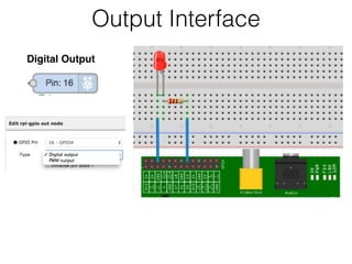
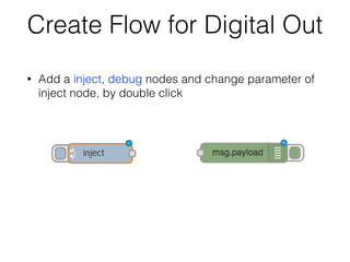
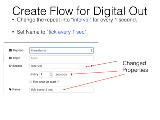
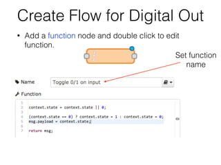
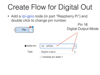
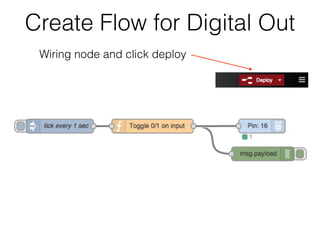
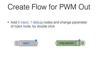
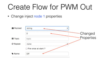
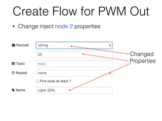
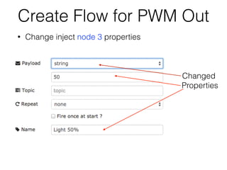

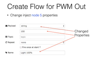
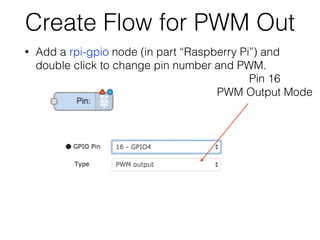
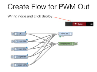
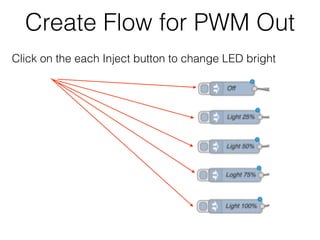
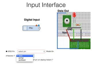
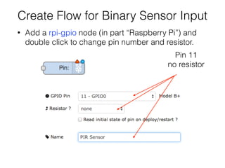
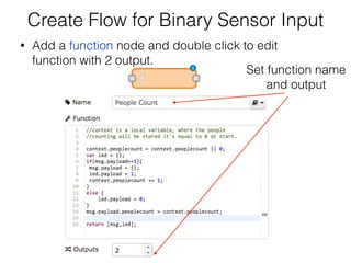
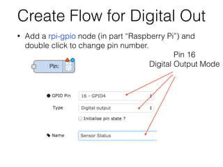

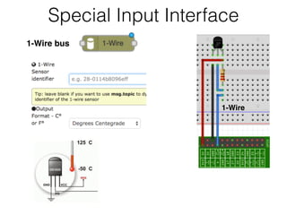
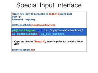
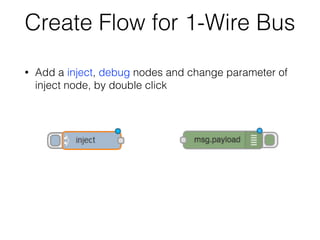
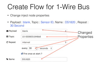
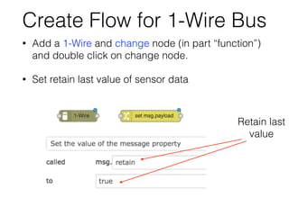
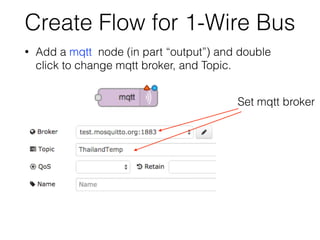
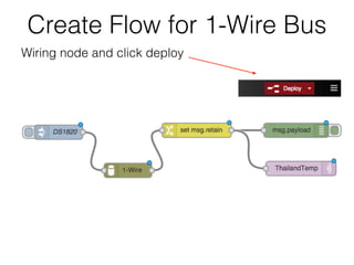
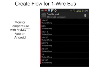

The document discusses using the Raspberry Pi's GPIO pins to control hardware interfaces with Node-RED. It provides examples of creating Node-RED flows to: 1. Control an LED by setting a GPIO pin as a digital output and toggling it on and off. 2. Control LED brightness using PWM by setting a GPIO pin as a PWM output and changing the duty cycle. 3. Read input from a binary sensor by setting a GPIO pin as a digital input and reading its state. 4. Read temperature from a 1-Wire temperature sensor connected to the Raspberry Pi's 1-Wire bus using a Node-RED 1-Wire node.