SlideShare a Scribd company logo
1 of 66
Download to read offline
AutoCAD Workbook II
AutoCAD Workbook II
Parviz D. Entekhabi
DRA 53
Hartnell College
Engineering Technology
©
Parviz D. Entekhabi
1
AutoCAD Workbook II
Lesson 01
Polyline Command
You may select this command from pull-down menu, draw-toolbar, or type alias “PL”
from the command line.
Command: pl <Enter>
Specify start point: 2,2 <Enter>
Current line-width is 0.0000
Specify next point or [Arc/Close/Halfwidth/Length/Undo/Width]: w <Enter>
Specify starting width <0.0000>: 0.1 <Enter>
Specify ending width <0.1000>: <Enter>
Specify next point or [Arc/Close/Halfwidth/Length/Undo/Width]: 5,1 <Enter>
Specify next point or [Arc/Close/Halfwidth/Length/Undo/Width]: @1.5<90 <Enter>
Specify next point or [Arc/Close/Halfwidth/Length/Undo/Width]: @3.5,0 <Enter>
Specify next point or [Arc/Close/Halfwidth/Length/Undo/Width]: @2.5<120 <Enter>
Specify next point or [Arc/Close/Halfwidth/Length/Undo/Width]: @5<180 <Enter>
2
AutoCAD Workbook II
Specify next point or [Arc/Close/Halfwidth/Length/Undo/Width]: C
<Enter>
Exercise Polyline (ARC)
Start AutoCAD and open the my_template52 file.
Command: pl <Enter>
PLINE
Specify start point: 5.25,4 <Enter>
Current line-width is 0.0000
Specify next point or [Arc/Close/Halfwidth/Length/Undo/Width]: w <Enter>
Specify starting width <0.0000>: 0.1 <Enter>
Specify ending width <0.1000>: <Enter>
Specify next point or [Arc/Halfwidth/Length/Undo/Width]: @2<0 <Enter>
Specify next point or [Arc/Close/Halfwidth/Length/Undo/Width]: a <Enter>
Specify endpoint of arc or
[Angle/CEnter/CLose/Direction/Halfwidth/Line/Radius/Second pt/Undo/Width]: @1<90
<Enter>
Specify endpoint of arc or
[Angle/CEnter/CLose/Direction/Halfwidth/Line/Radius/Second pt/Undo/Width]: @2.5<90
<<Enter>
Specify endpoint of arc or
[Angle/CEnter/CLose/Direction/Halfwidth/Line/Radius/Second pt/Undo/Width]: L <Enter>
Specify next point or [Arc/Close/Halfwidth/Length/Undo/Width]: @.5<90 <Enter>
Specify next point or [Arc/Close/Halfwidth/Length/Undo/Width]: @2<180 <Enter>
Specify next point or [Arc/Close/Halfwidth/Length/Undo/Width]: <Enter>
3
AutoCAD Workbook II
Figure 1 Figure 2
Use the MIRROR Command to complete the figure.
Command: mirror <Enter>
Select objects: {Pick the polyline} 1 found
Select objects: <Enter>
Specify first point of mirror line: {Snap to point 1} Specify second point of mirror line: {Snap
to point 2}
Erase source objects? [Yes/No] <N>: <Enter>
4
AutoCAD Workbook II
EXERCISE 1-2
Figure 1
5
AutoCAD Workbook II
Use the PLINE Command to draw the following objects with a .032 line width. Add dimensions.
EXERCISE 1-3
EXERCISE 1-4
6
AutoCAD Workbook II
Lesson 2
MULTI - LINE Command
1. From the format select “Mutiline Style (Figure 1)
2. Select the “Modify” tab from the dialog box (Figure 2)
7
Figure 1
Figure 2
3. Change the offset
distance for the
multilane
elements to .125
& -.125. (Figure 3
4. Clock the OK tab
to exit the modify,
and click the OK
tab to exit the
Multiline style the
dialog box.
Figure 3
AutoCAD Workbook II
Command: ml <Enter>
MLINE
Current settings: Justification = Top, Scale = 1.00, Style =
STANDARD
Specify start point or [Justification/Scale/STyle]:J<Enter>
Enter justification type [Top/Zero/Bottom] <top>:Z <Enter>
Current settings: Justification = Zero, Scale = 1.00, Style =
STANDARD
Specify start point or [Justification/Scale/STyle]: {Pick any
point on screen}
Specify next point: <Ortho on> 1.5 <Enter>
Specify next point or [Undo]: 2.5 <Enter>
Specify next point or [Close/Undo]: 1.5 <Enter>
Specify next point or [Close/Undo]: C <Enter> (Figure 4)
Command: ml <Enter>
MLINE
Current settings: Justification = Zero, Scale = 1.00, Style =
STANDARD
Specify start point or [Justification/Scale/STyle]: j <Enter>
Enter justification type [Top/Zero/Bottom] <zero>: b <Enter>
Current settings: Justification = Bottom, Scale = 1.00, Style =
STANDARD
Specify start point or [Justification/Scale/STyle]:
Specify next point: <Ortho on> 1.5 <Enter>
Specify next point or [Undo]: 2.5 <Enter>
Specify next point or [Close/Undo]: 1.5 <Enter>
Specify next point or [Close/Undo]: c <Enter> (Figure 5)
Figure 4
Zero Justification
Figure 5
Bottom Justification
8
AutoCAD Workbook II
Command: ml
MLINE
Current settings: Justification = Bottom, Scale = 1.00,
Style = STANDARD
Specify start point or [Justification/Scale/STyle]: j
Enter justification type [Top/Zero/Bottom] <bottom>: t
Current settings: Justification = Top, Scale = 1.00,
Style = STANDARD
Specify start point or [Justification/Scale/STyle]:
Specify next point: 1.5
Specify next point or [Undo]: 2.5
Specify next point or [Close/Undo]: 1.5
Specify next point or [Close/Undo]: c
Exercise 2-1
Draw the proposed electrical circuit using multilane commands. Establish a line offset
proportional to the given layout. Use t5he phantom linetype for the center of each run. Do not
draw the grid, which is provided as a drawing aid.
Note: Create a new Multiline Style with the following settings:
9
AutoCAD Workbook II
10
AutoCAD Workbook II
Exercise 2-2
OFFICE Building Project-
Settings:
Scale : 1/8 “ = 1’-0” ; Scale factor = 96
Limits:
Lower left corner <0'-0",0'-0">; upper right corner <84'-0",64'-0">:
Units: Architectural
1. From pull_down menu “Format” select Multiline Style, or type MLSTYLE from the
command line. (Fig. 1)
2. Click on the “New” Tab to create a new style. (Fig. 2), called “Ext_Wall” (Fig. 3).
Click on the “Continue” tab.
3. Add a new line to this style with green color and 7 as offset distance. Change other lines
to -3 and 3 for the offset distance.(See fig 4)
4. Set this style to the current and click on the OK tab. (Fig 5)
11
5. With this Multi Line draw the out side wall.
AutoCAD Workbook II
Figure 1
Figure 2
Figure 3
12
AutoCAD Workbook II
Figure 4
13
Figure 5
AutoCAD Workbook II
Command: ml <Enter>
MLINE
Current settings: Justification = Top, Scale = 1.00, Style =
EX_WALL
Specify start point or [Justification/Scale/STyle]: 31’,41’
<Enter>
Specify next point: 25' <Enter> {Make sure that ORTHO
mode is set to ON.
Specify next point or [Undo]: 19'8 <Enter>
Specify next point or [Close/Undo]: 12'8 <Enter>
Specify next point or [Close/Undo]: 2'4 <Enter>
Specify next point or [Close/Undo]: 10'4 <Enter>
Specify next point or [Close/Undo]: 8'8 <Enter>
Specify next point or [Close/Undo]: 2' <Enter>
Specify next point or [Close/Undo]: c <Enter>
Command:
Figure 6
6. Create a new multi line style
called INT_Wall. (Fig. 6) For
this style, delete the third line
(green). Fig 7.
Figure 6
14
Figure 7
AutoCAD Workbook II
7. Add the two interior walls (Fig. 8)
Command: ml <Enter>
MLINE
Current settings: Justification = Top, Scale =
1.00, Style = INT_WALL
Specify start point or
[Justification/Scale/STyle]: j <Enter>
Enter justification type [Top/Zero/Bottom]
<top>: b <Enter>
Current settings: Justification = Bottom, Scale
= 1.00, Style = INT_WALL
Specify start point or
[Justification/Scale/STyle]: {snap to the END
point A} Fig. 8
Specify next point: _per to {snap to the
Perpendicular to line B}
Specify next point or [Undo]:
Command: ml <Enter>
MLINE
Current settings: Justification = Bottom, Scale
= 1.00, Style = INT_WALL
Specify start point or
[Justification/Scale/STyle]: j <Enter>
Enter justification type [Top/Zero/Bottom]
<bottom>: t <Enter>
Current settings: Justification = Top, Scale =
1.00, Style = INT_WALL
Specify start point or
[Justification/Scale/STyle]: {snap to the End to
line C}
Specify next point: _per to {snap to the
Perpendicular to line D}
Figure 8
7. From the “Modify” pul;_down
menu, Object, select the
multiline. Fig 9.
8. Select the “Open Tee” option.
Fig 10.
Figure 9
15
AutoCAD Workbook II
16
Figure 10
Command: _mledit <Enter>
Select first mline or [Undo]: {Select the wall C}
Select second mline: {Select the wall D}
Select first mline or [Undo]: {Select the wall D}
Select second mline: {Select the wall B}
Select first mline or [Undo]: <Enter>
9. Using the insert command or through the “Design center” add
the doors and window shown in figure 11. Use the “Cut All”
or “Cut Single” from multiline edit to complete the project.
10. Add dimensions as shown.
Figure 16
AutoCAD Workbook II
17
Lesson 3
SPLINE Command
.
Figure 1
A spline drawn with the SPLINE command.
AutoCAD’s default start and end tangents were
used for this spline
Figure 2
Using the Close option of the SPLINE
command with AutoCAD default tangents to
draw a closed spline.
Note: Edit the spline (SPE) in Figure 1, and
choose the Close option.
Figure 3
These splines were drawn through the same points,
but they have different start and end tangent
directions. The arrows indicate the tangent
directions.
Figure 4
Use the follwing steps to edit the spline in the Figure
3, to create the spline in Figure 4.
Note: Turn the ORTHO “ON”, to define the tangent
directions.
AutoCAD Workbook II
18
SPLINEDIT Command
Command: spe <Enter>
SPLINEDIT
Select spline:
Enter an option [Fit data/Close/Move vertex/Refine/rEverse/Undo]: F <Enter>
Enter a fit data option
[Add/Close/Delete/Move/Purge/Tangents/toLerance/eXit] <eXit>: T <Enter>
Specify start tangent or [System default]: <Ortho on> {pick a point to define a new direction}
Specify end tangent or [System default]: {pick a point to define a new direction}
Enter a fit data option
[Add/Close/Delete/Move/Purge/Tangents/toLerance/eXit] <eXit>: X <Enter>
Enter an option [Fit data/Close/Move vertex/Refine/rEverse/Undo]: <Enter>
Exercise 3-1.
Use SPILNE and other commands, such as ELLIPSE, MIRROR, and OFFSET, to design an
architectural door knocker similar to the one shown. Use an appropriate text font to place your
initials in the center.
AutoCAD Workbook II
19
Exercise 3-2. (Problem page 516 )
Draw a spline similar to the original spline shown below. Copy the spline seven times to create a
layout similar to one given. Perform the SPLINEDIT (SPE) operation identified under each of
the seven copies.
Original Spline
Close Option
Move a Control Point Elevate the Order to 10
Add Two Control Points Delete a Control Point
Edit the Tangents
Increase the Weight of a Control
Point to 4
AutoCAD Workbook II
20
Exercise 3-3
AutoCAD Workbook II
21
Exercise 3-4
Use the POLYLINE command to construct the frame, the LINE for the spokes and
DONUT for the tires. Use grid spacing 0.25.
.
AutoCAD Workbook II
22
Lesson 4
Advanced Dimensions
MLEADER with BUBBLES
1. To create a new multi-leader style, start the MLEADERSTYLE command:
a. From the Format menu, choose Multileadr Style.
b. At the ‘ Command:’ prompt, enter mleader command.
c. In the dashboard, or from the Multileader toolbar, choose the Multileader Style
button.
d. Or, at the ‘ Command:’ prompt, enter mls alias.
2. To create a new style click New.
3. Enter the name for the style. For this exercise, enter “Round Bubble,” and then click
Continue.
4. Since we want to change the content of the mleader, choose the Content tab.
5. From the Multileader Type drop list, select Block.
6. Notice that the dialog box changes to show options related to the blocks. From the Source
Block drop list, select Circle.
7. Click OK to exit the first dialog boix. Click Set Current to make this new style current.
Click Close to exit the second dialog box.
AutoCAD Workbook II
23
8. Use the MLEADER command to place muliteader with the new style.
Command: mleader <Enter>
Specify leader arrowhead location or [leader Landing first/Content
first/Options] <Options>: {pick a point.}
Specify leader landing location: {pick another point}
Enter attribute values
Enter tag number <TAGNUMBER>: 1 <Enter>
ALTERNATIVE METHOD:
9. Press Ctrl + 3 to open the Tool Palettes window.
10. Pick the leaders Tab from the left of the tool palettes set. (Figure 10)
11. Construct the following figures:


AutoCAD Workbook II
24
Figure 7
DIMENSIONING
Alternate Practices - Arrowless Dimensions
Ordinate dimensions measure the perpendicular distance from an origin point called the datum to
a feature, such as a hole in a part. These dimensions prevent escalating errors by maintaining
accurate offsets of the features from the datum.
Ordinate dimensions consist of an X or Y value with a leader line. X-datum ordinate
dimensions measure the distance of a feature from the datum along the X axis. Y-datum
ordinate dimensions measure the distance along the Y axis.
AutoCAD Workbook II
Locate the Datum:
The location and orientation of the current UCS determines the ordinate values. Before
creating ordinate dimensions, you typically set the UCS origin to coincide with the
datum.
Exercise 4-2
Complete the drawing shown in Figure 10. Follow the steps below to add the
dimensions.
1. From Pull-down menu, Tools, select New UCS, Origin.
2. Define the new origin by picking the exact location at the lower left corner of the
part. (Figure 11)
3. From the”View “, “Display”, UCS Icon Uncheck the “On” option. You may do
this by typing the UCSICON from the Command line.
4. Place all the center marks, and check for other appropriate dimension settings.
5. Use the “Ordinate Dimension” to add the dimensions.
Figure 8
25
HOLE QTY DIAMETER
A 2 .500
B 1 .375
C 2 .250
AutoCAD Workbook II
26
Exercise 4-3
Figure 9
AutoCAD Workbook II
27
Lesson 5
Dimensions with Tolerance
Lateral tolerances are values indicating the amount a measured distance can vary. You can
control whether lateral tolerances are displayed and you can choose from several styles of lateral
tolerances.
A lateral tolerance specifies the amount by which a dimension can vary. By specifying tolerances
in manufacturing, you can control the degree of accuracy needed for a feature. A feature is some
aspect of a part, such as a point, line, axis, or surface.
You can apply tolerances directly to a dimension by appending the tolerances to the dimension
text. These dimension tolerances indicate the largest and smallest permissible size of the
dimension. You can also apply geometric tolerances, which indicate deviations of form, profile,
orientation, location, and runout.
Lateral tolerances can be specified from theoretically exact measurements. These are called basic
dimensions and have a box drawn around them.
If the dimension value can vary in both directions, the plus and minus values you supply are
appended to the dimension value as deviation tolerances. If the deviation tolerance values are
equal, they are displayed with a ± sign and they are known as symmetrical. Otherwise, the plus
value goes above the minus value.
If the tolerances are applied as limits, the program uses the plus and minus values you supply to
calculate a maximum and minimum value. These values replace the dimension value. If you
specify limits, the upper limit goes above the lower.
Format Lateral Dimension
You can control the vertical placement of tolerance values relative to the main dimension text.
Tolerances can align with the top, middle, or bottom of the dimension text.
AutoCAD Workbook II
28
Along with vertical placement of tolerance values, you can also control the horizontal alignment
of the upper and lower tolerance values. The upper and lower tolerance values can be aligned
using either the operational symbols or decimal separators.
You can also control zero suppression as you can with the primary and alternate units.
Suppressing zeros in lateral tolerances has the same effect as suppressing them in the primary and
alternate units. If you suppress leading zeros, 0.5 becomes .5, and if you suppress trailing zeros,
0.5000 becomes 0.5.
To specify methods for lateral tolerances
1. Enter dimstyle at the command prompt.
2. In the Dimension Style Manager, select the style you want to change. Click Modify.
3. In the Modify Dimension Style dialog box, Tolerances tab, under Tolerance Format,
select a method from the Method list, and then do one of the following:
o If you select Limits, enter upper and lower tolerance deviation in the Upper
Value and Lower Value boxes.
o If you select Symmetrical tolerances, Lower Value is not available, because you
need only one tolerance value.
o If you select Basic, enter a value in Offset from Dim Line (on the Text tab) to
represent the gap between the text and its enclosing box.
4. Click OK.
5. Click Close to exit the Dimension Style Manager.
AutoCAD Workbook II
29
Figure 10
Figure 11
AutoCAD Workbook II
30
Leading box checked
AutoCAD Workbook II
31
AutoCAD Workbook II
32
AutoCAD Workbook II
33
Exercises
Draw and dimension necessary views for the following drawings to exact sizes. These problems
presented in isometric. Draw the proper orthographic (2D) views for each.
A. Apply dimensions accurately using ASME standards. Create dimension styles that suit
the specific needs of each drawing.
B. Create separate layers for the object lines and dimensions.
C. Assign the line weight of 0.6 mm for the object lines and default line weight for other
lines.
D. Place the following general notes in the lower left corner of the each drawing :
“NOTE:
a. UNLESS OTHERWISE SPECIFIED, ALL DIMENSIONS ARE IN
MILLIMETERS (or INCHES, as applicable)
b. REMOVE ALL BURRS AND SHRP EDGES.
c. INTERPRET PER ASME Y14.5M-1994”
E. Save the drawing.
Figure 12
AutoCAD Workbook II
34
Figure 13
Figure 14
AutoCAD Workbook II
35
1. Start a new drawing or use one of your templates.
2. Draw the figure 18 with the given dimensions. Follow the steps below to add the dimensions
as shown in Figure 19.
Figure 15
AutoCAD Workbook II
36
Adjust the following settings under the “Standard” dimension
style:
Fit: Overall Scale = 25.4
Primary units: Decimal -Check Trailing box
Text Height: 0.125
Add the linear dimension 1 as shown.
Create a new dimension style and set the following dimension
variables:
AutoCAD Workbook II
37
AutoCAD Workbook II
38
a. Click on OK, set the Tol-1
as a current dimension
style, add dimension 2, 3
and 4 as shown.
b. Set the “Standard” as a
current dimension style
and add dimension 1 as
shown.
c. Create a new dimension style
change the tolerance method to
Basic. Click OK.
d. Set “Tol-2” as current dime style
and add a linear dimension 5.
AutoCAD Workbook II
39
AutoCAD Workbook II
40
e. Create a new dimension style change the tolerance
method to Symmetrical. Click OK.
f. Set “Tol-3” as current dime style and add a
diameter dimension 6.
g. Use the Ed command to add “4X” to the diameter
# 6.
AutoCAD Workbook II
41
AutoCAD Workbook II
42
Lesson 6
Geometric Dimension and Tolerance
Tolerance command displays the geometric characteristic symbols for location,
orientation, form, profile, and runout.
Follow the steps below to add a feature control frame follow the steps below:
From the command line type tol and press enter.
.
Place the control frame box # 7 as shown.
AutoCAD Workbook II
43
AutoCAD Workbook II
44
AutoCAD Workbook II
45
AutoCAD Workbook II
46
AutoCAD Workbook II
47
Exercise 6-1
Exercise 6-2
AutoCAD Workbook II
48
Lesson 7
Isometric Drawings
The keyboard entry to enable isometric mode is as follows:
Command: snap <Enter>
Specify snap spacing or [ON/OFF/Aspect/Style/Type] <0.5000>: s
<Enter>
Enter snap grid style [Standard/Isometric] <S>: i
Specify vertical spacing <0.5000>: <Enter>
Or, the Drafting Settings dialog box allows you to make settings needed
for isometric drawing:
Note:
To switch between the isometric planes, use the F5 Key, or the
[Ctrl] + [E] key combinations.
AutoCAD Workbook II
49
To pace an isometric ellipse on the object use Isocircle of the ELLIPSE
command.
AutoCAD Workbook II
50
TEXT & Dimension on Isometric:
Figure 16
Figure 17
AutoCAD Workbook II
51
Figure 18
Figure 19
AutoCAD Workbook II
52
Lesson 8; DIVIDE_POINT
1. Draw a circle with 1.60 radius.
2. From format “point style” select the X
mark for point shape. (Figures A&B)
3. Dive the circle in 5 equal parts with
the DIVIDE Command (1)
4. Turn on the node object snap, and
connect the points with the LINE
command. (2)
5. Use the TRIM command as shown.
(3)
6. ROTATE the entire object to the
position shown (4). Rotation base
is the center and the rotation angle
is 90º. { If the Ortho is ON this can
be done easily withthe mouse
click.}
Figure A
Figure B
AutoCAD Workbook II
53
DIVIDE Command with block option.
Figure 20
Figure 21
AutoCAD Workbook II
54
MINSERT Command
Figure 22
Create these electronic symbols, and then 0use them on a schematic drawing using the INSERT
command:
Suggested Settings: Snap (0.05); Grid (0.05)
AutoCAD Workbook II
55
Figure 23
AutoCAD Workbook II
56
BLOCKS with ATTRIBUTES
Figure 24
AutoCAD Workbook II
57
Creating a Dynamic Block
We’ll start with the shape of a twin-size bed and add parameter and action that will allow
its length and width to be stretched into a bed of any size.
1. Start AutoCAD and start a new drawing with default units.
2. Using the LIMITS command set the drawing area to 120 X100 and ZOOM All.
3. Create the top view of a twin-size bed using dimension shown in Figure1. Do not include
the dimensions in your drawing. These are standard dimension for a twin-bed.
Figure 25
4. Name the drawing bed.dwg.
5. Pick the Make Block button from the Draw toolbar or enter the BLOCK command to
display the Block Definition dialog box.
6. Name the block Bed, pick the lower left corner of the bed for the base point, and select
the entire bed to be included in the block.
7. Near the bottom of the dialog box, check Open in block editor box.
8. Pick OK to close the dialog box and open the new block in the block editor.
Assigning Parameter to the Block
1. In the block Authoring Pallets window, select the parameters tab if it is not already
selected.
2. From the available options, pick Linear Parameter.
3. Pick the bottom left corner of the bed as the start point and bottom right corner of the bed
as the endpoint. Be sure to snap accurately to these two points.
4. Indicate a point inside the bed for the label location, as shown in Figure 2.
Figure 26
AutoCAD Workbook II
58
Notice that parameter is automatically labeled “Distance”. Also notice the yellow icon with
exclamation mark near the lower left corner of the bed. This symbol means that parameter is
not currently associated with any action. You will set up the actions later. First, let’s create a
second parameter.
5. From the block Authoring Pallets window, pick “Linear Parameter” again. This time,
pick the lower left corner as the start point and the upper left corner for the endpoint.
Place the label inside the bed, as shown in Figure 3.
Figure 27
6. Select the first Distance Parameter you created, right-click to display the shortcut menu,
and pick Rename, and press Enter.
7. Highlight the word Distance, enter Length for the new name, and press Enter.
8. Select the Distance 1 parameter and rename it Width.
NOTE: You can also name parameters at the time you create them. Before you specify the
parameter, Press “N” to enter the Name option.
9. Pick the Length parameter, right-click, and select Grip Display.
10. Pick a Grip Display of 1.
11. Change the Grip Display of Width parameter to 1.
12. Save your work.
Figure 28
Assigning Actions to the Parameters
The two parameters that you have established will allow you to adjust both the length and
the width of the dynamic block named Bed. Next, we will set up the action to be associated
with each parameter.
1. Expand the Action Parameters panel on the Block Editor tab or Ribbon and select the
Show All Action button.
AutoCAD Workbook II
59
Note: You can also define an Action using the Action tab of the Block Authoring Pallets
window.
2. Pick the down-facing arrow below the Move button on the Action Parameters panel, and
select the Linear action button from the fly-out menu.
3. Select the Length parameter.
Notice that a red symbol appears at the lower right corner of the bed.
4. Pick the point in the lower right corner of the bed as the parameter point to associate with
the action.
5. In reply to Specify first corner of stretch frame, use a standard crossing window (right to
left selection). Place the widow as shown in Figure. Be sure to include the interior line
that represents the bed covers in the crossing window.
6. At the Select Objects prompt use another crossing window to select roughly the same
area. Press ENTER when you are finished.
7. Pick the Stretch action icon, right-click, and pick Rename Action.
8. Rename the action Stretch length.
Figure 29
Next, we will define the action needed to change the width of the bed.
9. Pick the Stretch button again and select the width parameter.
10. Pick the endpoint at the upper left corner as the parameter point to associate with the
action.
11. For the stretch frame, place a crossing window across the upper half of the bed, as shown
in Fig. 5.
12. At the Select object prompt, use another crossing window to select roughly the same
area. Press ENTER when you are finished.
13. Rename the action to Stretch Width.
The Length and width parameters are now completely defined, so the alert icons for the
parameters have disappeared. Your block should now look similar to the one in Fig. 34-6.
14. Pick the Close Block Editor button on the Close panel of the Ribbon to return to the
AutoCAD window.
15. Pick Yes when prompted to save changes to the Bed block.
AutoCAD Workbook II
60
Figure 30
Using Dynamic Blocks
The Bed block should now appear in AutoCAD’s drawing area. Next, we will change the
parameters of the block to change the size of the inserted block.
1- Select the Bed block.
Notice the arrows that appear instead of grip boxes at the upper left and lower right corners of the
bed. These arrows indicate changeable parameters.
2- Pick the arrow at the lower right corner of the bed and notice that it becomes active (red)
just as a grip would.
The Length parameter appears and an edit box appears to show the current length of the bed,
which is 75 inches.
3- Move the crosshairs and notice that the length of the bed changed dynamically.
4- At the keyboard, enter a new length of 80 and press ENTER to change the length of the
bed to 80 inches.
The bed updates automatically. This is the standard length for a queen-size, king-size, or extra-
long twin- size bed. Let’s change the width dimension to create a queen-size bed, which has a
standard width of 60 inches.
5- Select the bed again.
6- Pick the arrow at the upper left corner of the bed.
7- Enter a new width of 60.
Once again, the bed block automatically updates when you press ENTER.
Constraining parameters
It may have occurred to you that it is possible to change the dynamic Bed block to any length and
width using the dynamic block defined in the previous procedure. In real life, beds are usually
made to standard dimensions, as shown in Fig. 7.
AutoCAD Workbook II
61
Figure 31
Creating a Value Set
AutoCAD makes it easy to constrain, or limit, the choices that can be used for a given parameter.
You can do this by creating a value set for the parameter. For example, the three standard lengths
for a bed are 75, 80, and 84 inches. The following steps constrain the length parameter of the Bed
block using a value set that contains these three values.
1- Double-click the block to display the Edit Block Definition dialog box.
2- Select Bed and pick OK to enter the block editor.
3- Select the length parameter.
4- Select the Properties button from the Palettes panel on the view tab of the Ribbon.
This displays the properties of the linear parameter in the properties palette.
5- Near the bottom of the Properties palette, find the Value Set section and click to activate
the box next to Dist type. (You may need to scroll down to find this section.)
6- Pick the down arrow and then pick List from the options that appear.
Notice that the next row, Dist value list, now shows 75.0000. This is the value you used when
you originally created the block, and it becomes the default value.
7- Pick to activate the Dist value list row and pick the three dots to the right of the edit box.
This displays the Add Distance Value dialog box.
AutoCAD Workbook II
62
8- In the Distances to add edit box, enter 80 and pick the Add button.
The new value of 80.0000 appears in the window below the edit box.
9- With the cursor still active in the Distances to add edit box, enter 84 and pick the Add
button to add 84.0000 to the list.
10- Pick OK to close the dialog box.
11- Press ESC to deselect the Length parameter.
The standard widths for beds are 39, 54, 60, 72, 76 and 78. Let’s constrain the Width parameter
to these values.
12- With the properties palette still open, pick to select the Width parameter.
13- In the Dist type row in the Properties palette, change the value to List.
14- Click to activate the Dist value list row and pick the button with three dots to display the
Add Distance Value dialog box.
Once again, the default value appears in the window.
15- Add the other standard width values: 54, 60, 72, 76 and 78. Pick OK when you are
finished.
16- Close the properties palette and save the file. If AutoCAD displays a message asking
whether you want to save the drawing and update the existing block definition in the
drawing, pick Yes.
17- Close the block editor.
Using a Constrained Block
Constrained blocks can be altered on-screen in the same way as unconstrained dynamic blocks.
The only difference is that, when you pick one of the parameter arrows, small tick marks appear
to mark the valid values for the parameter.
1. Select the Bed block to display the parameter arrows.
2. Pick the lower right parameter arrow so that it turns red.
Just below the arrow, notice the faint tick markers on either side of current bed length. See
Figure 8.
You may recall that the bed is currently configured with dimensions for a queen-size bed: 60 X
80 inches. The 80 inches is one of the three standard values. The two tick mark the other two
values allowed for the Length parameter: 75 and 84. Let’s change the Bed block to represent a
full-size bed (54 x 75 inches).
3. Move the cursor to the left and notice that a tentative line appears at the 75-inch thick
mark.
4. Pick any point while that line is present to reset the length of the bed to 75 inches.
5. Pick the upper left parameter arrow to activate the Width parameter and notice the tick
marks representing allowed values.
The current value of 60 shows up in the edit box for reference.
6. Move the cursor down until the edit box shows a value of 54 and pick any point to
change the width of the bed to 54 inches.
The block is now configured to represent a full-size bed.
If you enter undefined value into the edit box for constrained parameter, AutoCAD automatically
chooses the defined value that is closest to the value you entered. For Example, if you entered a
value of 63 for the Width parameter, the width of the bed would change to 60, which is the
closest defined value set.
AutoCAD Workbook II
63
Analyzing 2D drawings, using AutoCAD’s INQUIRY features:
Figure 32
Calculate the surface area
AutoCAD Workbook II
64
ROTOR
1. The absolute coordinate value of the center of hole "A" is closest to
2. The perimeter of Rotor is
3. The distance from the center of arc "B" to the center of arc "C" is
4. The absolute coordinate value of the center of arc "D" is closest to
5. The total length of arc "F" is
6. The total area of Rotor with all four holes removed is
7. Change the diameter of all three 1.000 diameter holes to 0.700 diameters.
Change the diameter of the 2.550 hole to a new diameter of 1.625. The new area
of Rotor with all four holes removed is
Figure 33
AutoCAD Workbook II
65
Control Bearing
Start Point: Center at 11.5, 11.5.
1. The distance from center arc “A” to the intersection at “B” is
2. The total length of arc “C” is
3. The perimeter of inner slot “G” is
4. The absolute coordinate value of the center of the 0.44 diameter hole “F” is
5. The perimeter of the outmost shape of the Control Bearing is
6. The angled formed the XY plane from the intersection at “D” to the center of the arc “E”
is
7. The area of the Control Bearing with all holes and inner slot removed is
Figure 34
AutoCAD Workbook II
66
Additional problems
Figure 35

More Related Content

What's hot (20)

Catia
Catia Catia
Catia
 
Nx basics 2014
Nx basics 2014 Nx basics 2014
Nx basics 2014
 
Introduction to Fusion 360
Introduction to Fusion 360Introduction to Fusion 360
Introduction to Fusion 360
 
Drawing chapter 03 orthographic projection (1)
Drawing chapter 03 orthographic projection (1)Drawing chapter 03 orthographic projection (1)
Drawing chapter 03 orthographic projection (1)
 
02 bearing plummer block
02 bearing plummer block02 bearing plummer block
02 bearing plummer block
 
ppt on summer training on solidworks
ppt on summer training on solidworksppt on summer training on solidworks
ppt on summer training on solidworks
 
Catia sketcher workbench
Catia  sketcher workbenchCatia  sketcher workbench
Catia sketcher workbench
 
Introduction to AutoCAD Commands
Introduction to AutoCAD CommandsIntroduction to AutoCAD Commands
Introduction to AutoCAD Commands
 
Design of transmission elements
Design of transmission elementsDesign of transmission elements
Design of transmission elements
 
Introduction to CATIA
Introduction to CATIAIntroduction to CATIA
Introduction to CATIA
 
Pneumatic circuits
Pneumatic circuitsPneumatic circuits
Pneumatic circuits
 
Catia v5 NOTES
Catia v5  NOTESCatia v5  NOTES
Catia v5 NOTES
 
CNC Programming
CNC Programming CNC Programming
CNC Programming
 
Solidworks ppt 2015
Solidworks ppt 2015Solidworks ppt 2015
Solidworks ppt 2015
 
Solidworks ppt
Solidworks pptSolidworks ppt
Solidworks ppt
 
Universal Coupling Experiment
Universal Coupling ExperimentUniversal Coupling Experiment
Universal Coupling Experiment
 
8.acceleration analysis
8.acceleration analysis8.acceleration analysis
8.acceleration analysis
 
Afiche npc torques diesel
Afiche npc torques dieselAfiche npc torques diesel
Afiche npc torques diesel
 
Introduction to Engineering Drawing
Introduction to Engineering Drawing Introduction to Engineering Drawing
Introduction to Engineering Drawing
 
Catia File
Catia FileCatia File
Catia File
 

Similar to Auto cad workbook2d hartnell college engineering technology

Practical work 3
Practical work 3Practical work 3
Practical work 3wkhairil80
 
my ppt for autocad &autocad electrical
my ppt for autocad &autocad electricalmy ppt for autocad &autocad electrical
my ppt for autocad &autocad electricalh soundarya
 
Practical work 4
Practical work 4Practical work 4
Practical work 4wkhairil80
 
AutoCAD Lab Manual
AutoCAD Lab ManualAutoCAD Lab Manual
AutoCAD Lab ManualCynthia King
 
presentationprintTemp.ppt auto cad presentation
presentationprintTemp.ppt auto cad presentationpresentationprintTemp.ppt auto cad presentation
presentationprintTemp.ppt auto cad presentationvikramchandrachoudha
 
Auto cad3d yon dara
Auto cad3d yon daraAuto cad3d yon dara
Auto cad3d yon daraSRDOBKK
 
Practical work 5
Practical work 5Practical work 5
Practical work 5wkhairil80
 
3D_AutoCAD.pdf
3D_AutoCAD.pdf3D_AutoCAD.pdf
3D_AutoCAD.pdfazliana33k
 
AutoCAD - 3D Notes
AutoCAD - 3D NotesAutoCAD - 3D Notes
AutoCAD - 3D NotesVj NiroSh
 
3 d auto cad 2009
3 d auto cad 20093 d auto cad 2009
3 d auto cad 2009thuonglindo
 
3 d autocad_2009
3 d autocad_20093 d autocad_2009
3 d autocad_2009miguel70919
 

Similar to Auto cad workbook2d hartnell college engineering technology (20)

Practical work 3
Practical work 3Practical work 3
Practical work 3
 
New manual
New manualNew manual
New manual
 
Autocad electrical
Autocad electricalAutocad electrical
Autocad electrical
 
3d Model of “Bearing”
3d Model of “Bearing”3d Model of “Bearing”
3d Model of “Bearing”
 
my ppt for autocad &autocad electrical
my ppt for autocad &autocad electricalmy ppt for autocad &autocad electrical
my ppt for autocad &autocad electrical
 
Practical work 4
Practical work 4Practical work 4
Practical work 4
 
AutoCAD Lab Manual
AutoCAD Lab ManualAutoCAD Lab Manual
AutoCAD Lab Manual
 
presentationprintTemp.ppt auto cad presentation
presentationprintTemp.ppt auto cad presentationpresentationprintTemp.ppt auto cad presentation
presentationprintTemp.ppt auto cad presentation
 
บทนำ
บทนำบทนำ
บทนำ
 
Auto cad3d yon dara
Auto cad3d yon daraAuto cad3d yon dara
Auto cad3d yon dara
 
Practical work 5
Practical work 5Practical work 5
Practical work 5
 
3 d autocad
3 d autocad3 d autocad
3 d autocad
 
3D_AutoCAD.pdf
3D_AutoCAD.pdf3D_AutoCAD.pdf
3D_AutoCAD.pdf
 
3 d autocad
3 d autocad3 d autocad
3 d autocad
 
AutoCAD - 3D Notes
AutoCAD - 3D NotesAutoCAD - 3D Notes
AutoCAD - 3D Notes
 
3 d autocad_2009
3 d autocad_20093 d autocad_2009
3 d autocad_2009
 
Computer aided machine drawing
Computer aided machine drawingComputer aided machine drawing
Computer aided machine drawing
 
3 d auto cad 2009
3 d auto cad 20093 d auto cad 2009
3 d auto cad 2009
 
3 d autocad_2009
3 d autocad_20093 d autocad_2009
3 d autocad_2009
 
3 d autocad_2009
3 d autocad_20093 d autocad_2009
3 d autocad_2009
 

More from AlFakir Fikri AlTakiri

Notes-Engineering-Graphics-and-Design-1-.pdf
Notes-Engineering-Graphics-and-Design-1-.pdfNotes-Engineering-Graphics-and-Design-1-.pdf
Notes-Engineering-Graphics-and-Design-1-.pdfAlFakir Fikri AlTakiri
 
04 designing-plastic-products-injection-moulding
04 designing-plastic-products-injection-moulding04 designing-plastic-products-injection-moulding
04 designing-plastic-products-injection-mouldingAlFakir Fikri AlTakiri
 
(Without animation) animated timeline free power point template
(Without animation) animated timeline free power point template(Without animation) animated timeline free power point template
(Without animation) animated timeline free power point templateAlFakir Fikri AlTakiri
 
(With animation) animated timeline free power point template
(With animation) animated timeline free power point template(With animation) animated timeline free power point template
(With animation) animated timeline free power point templateAlFakir Fikri AlTakiri
 
Cambridge english vocabulary in use - pre-int int
Cambridge   english vocabulary in use - pre-int intCambridge   english vocabulary in use - pre-int int
Cambridge english vocabulary in use - pre-int intAlFakir Fikri AlTakiri
 
Cambridge english vocabulary in use - elem
Cambridge   english vocabulary in use - elemCambridge   english vocabulary in use - elem
Cambridge english vocabulary in use - elemAlFakir Fikri AlTakiri
 

More from AlFakir Fikri AlTakiri (20)

Notes-Engineering-Graphics-and-Design-1-.pdf
Notes-Engineering-Graphics-and-Design-1-.pdfNotes-Engineering-Graphics-and-Design-1-.pdf
Notes-Engineering-Graphics-and-Design-1-.pdf
 
Machine_Drawing.pdf
Machine_Drawing.pdfMachine_Drawing.pdf
Machine_Drawing.pdf
 
04 designing-plastic-products-injection-moulding
04 designing-plastic-products-injection-moulding04 designing-plastic-products-injection-moulding
04 designing-plastic-products-injection-moulding
 
10 study successful-calculation
10 study successful-calculation10 study successful-calculation
10 study successful-calculation
 
Auto cad 2020_shortcuts_guide
Auto cad 2020_shortcuts_guideAuto cad 2020_shortcuts_guide
Auto cad 2020_shortcuts_guide
 
Multi view dimensioning rules notes
Multi view dimensioning rules   notesMulti view dimensioning rules   notes
Multi view dimensioning rules notes
 
(Without animation) animated timeline free power point template
(Without animation) animated timeline free power point template(Without animation) animated timeline free power point template
(Without animation) animated timeline free power point template
 
(With animation) animated timeline free power point template
(With animation) animated timeline free power point template(With animation) animated timeline free power point template
(With animation) animated timeline free power point template
 
Cambridge english vocabulary in use - pre-int int
Cambridge   english vocabulary in use - pre-int intCambridge   english vocabulary in use - pre-int int
Cambridge english vocabulary in use - pre-int int
 
Cambridge english vocabulary in use - elem
Cambridge   english vocabulary in use - elemCambridge   english vocabulary in use - elem
Cambridge english vocabulary in use - elem
 
Basic english usage_[oxford]
Basic english usage_[oxford]Basic english usage_[oxford]
Basic english usage_[oxford]
 
Robot simulation for_control_design
Robot simulation for_control_designRobot simulation for_control_design
Robot simulation for_control_design
 
Win zip 17 code
Win zip 17 codeWin zip 17 code
Win zip 17 code
 
Rp percetakan
Rp percetakanRp percetakan
Rp percetakan
 
Panduan rancangan kewangan
Panduan rancangan kewanganPanduan rancangan kewangan
Panduan rancangan kewangan
 
Format penulisan rp
Format penulisan rpFormat penulisan rp
Format penulisan rp
 
Contoh rp
Contoh rpContoh rp
Contoh rp
 
Bantuan kewangan
Bantuan kewanganBantuan kewangan
Bantuan kewangan
 
Sme produk
Sme produkSme produk
Sme produk
 
Panduan pemasaran
Panduan pemasaranPanduan pemasaran
Panduan pemasaran
 

Recently uploaded

History Class XII Ch. 3 Kinship, Caste and Class (1).pptx
History Class XII Ch. 3 Kinship, Caste and Class (1).pptxHistory Class XII Ch. 3 Kinship, Caste and Class (1).pptx
History Class XII Ch. 3 Kinship, Caste and Class (1).pptxsocialsciencegdgrohi
 
KSHARA STURA .pptx---KSHARA KARMA THERAPY (CAUSTIC THERAPY)————IMP.OF KSHARA ...
KSHARA STURA .pptx---KSHARA KARMA THERAPY (CAUSTIC THERAPY)————IMP.OF KSHARA ...KSHARA STURA .pptx---KSHARA KARMA THERAPY (CAUSTIC THERAPY)————IMP.OF KSHARA ...
KSHARA STURA .pptx---KSHARA KARMA THERAPY (CAUSTIC THERAPY)————IMP.OF KSHARA ...M56BOOKSTORE PRODUCT/SERVICE
 
DATA STRUCTURE AND ALGORITHM for beginners
DATA STRUCTURE AND ALGORITHM for beginnersDATA STRUCTURE AND ALGORITHM for beginners
DATA STRUCTURE AND ALGORITHM for beginnersSabitha Banu
 
Full Stack Web Development Course for Beginners
Full Stack Web Development Course  for BeginnersFull Stack Web Development Course  for Beginners
Full Stack Web Development Course for BeginnersSabitha Banu
 
MARGINALIZATION (Different learners in Marginalized Group
MARGINALIZATION (Different learners in Marginalized GroupMARGINALIZATION (Different learners in Marginalized Group
MARGINALIZATION (Different learners in Marginalized GroupJonathanParaisoCruz
 
Employee wellbeing at the workplace.pptx
Employee wellbeing at the workplace.pptxEmployee wellbeing at the workplace.pptx
Employee wellbeing at the workplace.pptxNirmalaLoungPoorunde1
 
Capitol Tech U Doctoral Presentation - April 2024.pptx
Capitol Tech U Doctoral Presentation - April 2024.pptxCapitol Tech U Doctoral Presentation - April 2024.pptx
Capitol Tech U Doctoral Presentation - April 2024.pptxCapitolTechU
 
Enzyme, Pharmaceutical Aids, Miscellaneous Last Part of Chapter no 5th.pdf
Enzyme, Pharmaceutical Aids, Miscellaneous Last Part of Chapter no 5th.pdfEnzyme, Pharmaceutical Aids, Miscellaneous Last Part of Chapter no 5th.pdf
Enzyme, Pharmaceutical Aids, Miscellaneous Last Part of Chapter no 5th.pdfSumit Tiwari
 
ECONOMIC CONTEXT - LONG FORM TV DRAMA - PPT
ECONOMIC CONTEXT - LONG FORM TV DRAMA - PPTECONOMIC CONTEXT - LONG FORM TV DRAMA - PPT
ECONOMIC CONTEXT - LONG FORM TV DRAMA - PPTiammrhaywood
 
Roles & Responsibilities in Pharmacovigilance
Roles & Responsibilities in PharmacovigilanceRoles & Responsibilities in Pharmacovigilance
Roles & Responsibilities in PharmacovigilanceSamikshaHamane
 
ECONOMIC CONTEXT - PAPER 1 Q3: NEWSPAPERS.pptx
ECONOMIC CONTEXT - PAPER 1 Q3: NEWSPAPERS.pptxECONOMIC CONTEXT - PAPER 1 Q3: NEWSPAPERS.pptx
ECONOMIC CONTEXT - PAPER 1 Q3: NEWSPAPERS.pptxiammrhaywood
 
Proudly South Africa powerpoint Thorisha.pptx
Proudly South Africa powerpoint Thorisha.pptxProudly South Africa powerpoint Thorisha.pptx
Proudly South Africa powerpoint Thorisha.pptxthorishapillay1
 
Interactive Powerpoint_How to Master effective communication
Interactive Powerpoint_How to Master effective communicationInteractive Powerpoint_How to Master effective communication
Interactive Powerpoint_How to Master effective communicationnomboosow
 
How to Configure Email Server in Odoo 17
How to Configure Email Server in Odoo 17How to Configure Email Server in Odoo 17
How to Configure Email Server in Odoo 17Celine George
 
Hierarchy of management that covers different levels of management
Hierarchy of management that covers different levels of managementHierarchy of management that covers different levels of management
Hierarchy of management that covers different levels of managementmkooblal
 
Earth Day Presentation wow hello nice great
Earth Day Presentation wow hello nice greatEarth Day Presentation wow hello nice great
Earth Day Presentation wow hello nice greatYousafMalik24
 

Recently uploaded (20)

History Class XII Ch. 3 Kinship, Caste and Class (1).pptx
History Class XII Ch. 3 Kinship, Caste and Class (1).pptxHistory Class XII Ch. 3 Kinship, Caste and Class (1).pptx
History Class XII Ch. 3 Kinship, Caste and Class (1).pptx
 
Model Call Girl in Tilak Nagar Delhi reach out to us at 🔝9953056974🔝
Model Call Girl in Tilak Nagar Delhi reach out to us at 🔝9953056974🔝Model Call Girl in Tilak Nagar Delhi reach out to us at 🔝9953056974🔝
Model Call Girl in Tilak Nagar Delhi reach out to us at 🔝9953056974🔝
 
TataKelola dan KamSiber Kecerdasan Buatan v022.pdf
TataKelola dan KamSiber Kecerdasan Buatan v022.pdfTataKelola dan KamSiber Kecerdasan Buatan v022.pdf
TataKelola dan KamSiber Kecerdasan Buatan v022.pdf
 
KSHARA STURA .pptx---KSHARA KARMA THERAPY (CAUSTIC THERAPY)————IMP.OF KSHARA ...
KSHARA STURA .pptx---KSHARA KARMA THERAPY (CAUSTIC THERAPY)————IMP.OF KSHARA ...KSHARA STURA .pptx---KSHARA KARMA THERAPY (CAUSTIC THERAPY)————IMP.OF KSHARA ...
KSHARA STURA .pptx---KSHARA KARMA THERAPY (CAUSTIC THERAPY)————IMP.OF KSHARA ...
 
DATA STRUCTURE AND ALGORITHM for beginners
DATA STRUCTURE AND ALGORITHM for beginnersDATA STRUCTURE AND ALGORITHM for beginners
DATA STRUCTURE AND ALGORITHM for beginners
 
Full Stack Web Development Course for Beginners
Full Stack Web Development Course  for BeginnersFull Stack Web Development Course  for Beginners
Full Stack Web Development Course for Beginners
 
MARGINALIZATION (Different learners in Marginalized Group
MARGINALIZATION (Different learners in Marginalized GroupMARGINALIZATION (Different learners in Marginalized Group
MARGINALIZATION (Different learners in Marginalized Group
 
Employee wellbeing at the workplace.pptx
Employee wellbeing at the workplace.pptxEmployee wellbeing at the workplace.pptx
Employee wellbeing at the workplace.pptx
 
Capitol Tech U Doctoral Presentation - April 2024.pptx
Capitol Tech U Doctoral Presentation - April 2024.pptxCapitol Tech U Doctoral Presentation - April 2024.pptx
Capitol Tech U Doctoral Presentation - April 2024.pptx
 
Enzyme, Pharmaceutical Aids, Miscellaneous Last Part of Chapter no 5th.pdf
Enzyme, Pharmaceutical Aids, Miscellaneous Last Part of Chapter no 5th.pdfEnzyme, Pharmaceutical Aids, Miscellaneous Last Part of Chapter no 5th.pdf
Enzyme, Pharmaceutical Aids, Miscellaneous Last Part of Chapter no 5th.pdf
 
ECONOMIC CONTEXT - LONG FORM TV DRAMA - PPT
ECONOMIC CONTEXT - LONG FORM TV DRAMA - PPTECONOMIC CONTEXT - LONG FORM TV DRAMA - PPT
ECONOMIC CONTEXT - LONG FORM TV DRAMA - PPT
 
Roles & Responsibilities in Pharmacovigilance
Roles & Responsibilities in PharmacovigilanceRoles & Responsibilities in Pharmacovigilance
Roles & Responsibilities in Pharmacovigilance
 
ECONOMIC CONTEXT - PAPER 1 Q3: NEWSPAPERS.pptx
ECONOMIC CONTEXT - PAPER 1 Q3: NEWSPAPERS.pptxECONOMIC CONTEXT - PAPER 1 Q3: NEWSPAPERS.pptx
ECONOMIC CONTEXT - PAPER 1 Q3: NEWSPAPERS.pptx
 
Proudly South Africa powerpoint Thorisha.pptx
Proudly South Africa powerpoint Thorisha.pptxProudly South Africa powerpoint Thorisha.pptx
Proudly South Africa powerpoint Thorisha.pptx
 
OS-operating systems- ch04 (Threads) ...
OS-operating systems- ch04 (Threads) ...OS-operating systems- ch04 (Threads) ...
OS-operating systems- ch04 (Threads) ...
 
Interactive Powerpoint_How to Master effective communication
Interactive Powerpoint_How to Master effective communicationInteractive Powerpoint_How to Master effective communication
Interactive Powerpoint_How to Master effective communication
 
How to Configure Email Server in Odoo 17
How to Configure Email Server in Odoo 17How to Configure Email Server in Odoo 17
How to Configure Email Server in Odoo 17
 
Model Call Girl in Bikash Puri Delhi reach out to us at 🔝9953056974🔝
Model Call Girl in Bikash Puri  Delhi reach out to us at 🔝9953056974🔝Model Call Girl in Bikash Puri  Delhi reach out to us at 🔝9953056974🔝
Model Call Girl in Bikash Puri Delhi reach out to us at 🔝9953056974🔝
 
Hierarchy of management that covers different levels of management
Hierarchy of management that covers different levels of managementHierarchy of management that covers different levels of management
Hierarchy of management that covers different levels of management
 
Earth Day Presentation wow hello nice great
Earth Day Presentation wow hello nice greatEarth Day Presentation wow hello nice great
Earth Day Presentation wow hello nice great
 

Auto cad workbook2d hartnell college engineering technology

  • 1. AutoCAD Workbook II AutoCAD Workbook II Parviz D. Entekhabi DRA 53 Hartnell College Engineering Technology © Parviz D. Entekhabi 1
  • 2. AutoCAD Workbook II Lesson 01 Polyline Command You may select this command from pull-down menu, draw-toolbar, or type alias “PL” from the command line. Command: pl <Enter> Specify start point: 2,2 <Enter> Current line-width is 0.0000 Specify next point or [Arc/Close/Halfwidth/Length/Undo/Width]: w <Enter> Specify starting width <0.0000>: 0.1 <Enter> Specify ending width <0.1000>: <Enter> Specify next point or [Arc/Close/Halfwidth/Length/Undo/Width]: 5,1 <Enter> Specify next point or [Arc/Close/Halfwidth/Length/Undo/Width]: @1.5<90 <Enter> Specify next point or [Arc/Close/Halfwidth/Length/Undo/Width]: @3.5,0 <Enter> Specify next point or [Arc/Close/Halfwidth/Length/Undo/Width]: @2.5<120 <Enter> Specify next point or [Arc/Close/Halfwidth/Length/Undo/Width]: @5<180 <Enter> 2
  • 3. AutoCAD Workbook II Specify next point or [Arc/Close/Halfwidth/Length/Undo/Width]: C <Enter> Exercise Polyline (ARC) Start AutoCAD and open the my_template52 file. Command: pl <Enter> PLINE Specify start point: 5.25,4 <Enter> Current line-width is 0.0000 Specify next point or [Arc/Close/Halfwidth/Length/Undo/Width]: w <Enter> Specify starting width <0.0000>: 0.1 <Enter> Specify ending width <0.1000>: <Enter> Specify next point or [Arc/Halfwidth/Length/Undo/Width]: @2<0 <Enter> Specify next point or [Arc/Close/Halfwidth/Length/Undo/Width]: a <Enter> Specify endpoint of arc or [Angle/CEnter/CLose/Direction/Halfwidth/Line/Radius/Second pt/Undo/Width]: @1<90 <Enter> Specify endpoint of arc or [Angle/CEnter/CLose/Direction/Halfwidth/Line/Radius/Second pt/Undo/Width]: @2.5<90 <<Enter> Specify endpoint of arc or [Angle/CEnter/CLose/Direction/Halfwidth/Line/Radius/Second pt/Undo/Width]: L <Enter> Specify next point or [Arc/Close/Halfwidth/Length/Undo/Width]: @.5<90 <Enter> Specify next point or [Arc/Close/Halfwidth/Length/Undo/Width]: @2<180 <Enter> Specify next point or [Arc/Close/Halfwidth/Length/Undo/Width]: <Enter> 3
  • 4. AutoCAD Workbook II Figure 1 Figure 2 Use the MIRROR Command to complete the figure. Command: mirror <Enter> Select objects: {Pick the polyline} 1 found Select objects: <Enter> Specify first point of mirror line: {Snap to point 1} Specify second point of mirror line: {Snap to point 2} Erase source objects? [Yes/No] <N>: <Enter> 4
  • 6. AutoCAD Workbook II Use the PLINE Command to draw the following objects with a .032 line width. Add dimensions. EXERCISE 1-3 EXERCISE 1-4 6
  • 7. AutoCAD Workbook II Lesson 2 MULTI - LINE Command 1. From the format select “Mutiline Style (Figure 1) 2. Select the “Modify” tab from the dialog box (Figure 2) 7 Figure 1 Figure 2 3. Change the offset distance for the multilane elements to .125 & -.125. (Figure 3 4. Clock the OK tab to exit the modify, and click the OK tab to exit the Multiline style the dialog box. Figure 3
  • 8. AutoCAD Workbook II Command: ml <Enter> MLINE Current settings: Justification = Top, Scale = 1.00, Style = STANDARD Specify start point or [Justification/Scale/STyle]:J<Enter> Enter justification type [Top/Zero/Bottom] <top>:Z <Enter> Current settings: Justification = Zero, Scale = 1.00, Style = STANDARD Specify start point or [Justification/Scale/STyle]: {Pick any point on screen} Specify next point: <Ortho on> 1.5 <Enter> Specify next point or [Undo]: 2.5 <Enter> Specify next point or [Close/Undo]: 1.5 <Enter> Specify next point or [Close/Undo]: C <Enter> (Figure 4) Command: ml <Enter> MLINE Current settings: Justification = Zero, Scale = 1.00, Style = STANDARD Specify start point or [Justification/Scale/STyle]: j <Enter> Enter justification type [Top/Zero/Bottom] <zero>: b <Enter> Current settings: Justification = Bottom, Scale = 1.00, Style = STANDARD Specify start point or [Justification/Scale/STyle]: Specify next point: <Ortho on> 1.5 <Enter> Specify next point or [Undo]: 2.5 <Enter> Specify next point or [Close/Undo]: 1.5 <Enter> Specify next point or [Close/Undo]: c <Enter> (Figure 5) Figure 4 Zero Justification Figure 5 Bottom Justification 8
  • 9. AutoCAD Workbook II Command: ml MLINE Current settings: Justification = Bottom, Scale = 1.00, Style = STANDARD Specify start point or [Justification/Scale/STyle]: j Enter justification type [Top/Zero/Bottom] <bottom>: t Current settings: Justification = Top, Scale = 1.00, Style = STANDARD Specify start point or [Justification/Scale/STyle]: Specify next point: 1.5 Specify next point or [Undo]: 2.5 Specify next point or [Close/Undo]: 1.5 Specify next point or [Close/Undo]: c Exercise 2-1 Draw the proposed electrical circuit using multilane commands. Establish a line offset proportional to the given layout. Use t5he phantom linetype for the center of each run. Do not draw the grid, which is provided as a drawing aid. Note: Create a new Multiline Style with the following settings: 9
  • 11. AutoCAD Workbook II Exercise 2-2 OFFICE Building Project- Settings: Scale : 1/8 “ = 1’-0” ; Scale factor = 96 Limits: Lower left corner <0'-0",0'-0">; upper right corner <84'-0",64'-0">: Units: Architectural 1. From pull_down menu “Format” select Multiline Style, or type MLSTYLE from the command line. (Fig. 1) 2. Click on the “New” Tab to create a new style. (Fig. 2), called “Ext_Wall” (Fig. 3). Click on the “Continue” tab. 3. Add a new line to this style with green color and 7 as offset distance. Change other lines to -3 and 3 for the offset distance.(See fig 4) 4. Set this style to the current and click on the OK tab. (Fig 5) 11 5. With this Multi Line draw the out side wall.
  • 12. AutoCAD Workbook II Figure 1 Figure 2 Figure 3 12
  • 13. AutoCAD Workbook II Figure 4 13 Figure 5
  • 14. AutoCAD Workbook II Command: ml <Enter> MLINE Current settings: Justification = Top, Scale = 1.00, Style = EX_WALL Specify start point or [Justification/Scale/STyle]: 31’,41’ <Enter> Specify next point: 25' <Enter> {Make sure that ORTHO mode is set to ON. Specify next point or [Undo]: 19'8 <Enter> Specify next point or [Close/Undo]: 12'8 <Enter> Specify next point or [Close/Undo]: 2'4 <Enter> Specify next point or [Close/Undo]: 10'4 <Enter> Specify next point or [Close/Undo]: 8'8 <Enter> Specify next point or [Close/Undo]: 2' <Enter> Specify next point or [Close/Undo]: c <Enter> Command: Figure 6 6. Create a new multi line style called INT_Wall. (Fig. 6) For this style, delete the third line (green). Fig 7. Figure 6 14 Figure 7
  • 15. AutoCAD Workbook II 7. Add the two interior walls (Fig. 8) Command: ml <Enter> MLINE Current settings: Justification = Top, Scale = 1.00, Style = INT_WALL Specify start point or [Justification/Scale/STyle]: j <Enter> Enter justification type [Top/Zero/Bottom] <top>: b <Enter> Current settings: Justification = Bottom, Scale = 1.00, Style = INT_WALL Specify start point or [Justification/Scale/STyle]: {snap to the END point A} Fig. 8 Specify next point: _per to {snap to the Perpendicular to line B} Specify next point or [Undo]: Command: ml <Enter> MLINE Current settings: Justification = Bottom, Scale = 1.00, Style = INT_WALL Specify start point or [Justification/Scale/STyle]: j <Enter> Enter justification type [Top/Zero/Bottom] <bottom>: t <Enter> Current settings: Justification = Top, Scale = 1.00, Style = INT_WALL Specify start point or [Justification/Scale/STyle]: {snap to the End to line C} Specify next point: _per to {snap to the Perpendicular to line D} Figure 8 7. From the “Modify” pul;_down menu, Object, select the multiline. Fig 9. 8. Select the “Open Tee” option. Fig 10. Figure 9 15
  • 16. AutoCAD Workbook II 16 Figure 10 Command: _mledit <Enter> Select first mline or [Undo]: {Select the wall C} Select second mline: {Select the wall D} Select first mline or [Undo]: {Select the wall D} Select second mline: {Select the wall B} Select first mline or [Undo]: <Enter> 9. Using the insert command or through the “Design center” add the doors and window shown in figure 11. Use the “Cut All” or “Cut Single” from multiline edit to complete the project. 10. Add dimensions as shown. Figure 16
  • 17. AutoCAD Workbook II 17 Lesson 3 SPLINE Command . Figure 1 A spline drawn with the SPLINE command. AutoCAD’s default start and end tangents were used for this spline Figure 2 Using the Close option of the SPLINE command with AutoCAD default tangents to draw a closed spline. Note: Edit the spline (SPE) in Figure 1, and choose the Close option. Figure 3 These splines were drawn through the same points, but they have different start and end tangent directions. The arrows indicate the tangent directions. Figure 4 Use the follwing steps to edit the spline in the Figure 3, to create the spline in Figure 4. Note: Turn the ORTHO “ON”, to define the tangent directions.
  • 18. AutoCAD Workbook II 18 SPLINEDIT Command Command: spe <Enter> SPLINEDIT Select spline: Enter an option [Fit data/Close/Move vertex/Refine/rEverse/Undo]: F <Enter> Enter a fit data option [Add/Close/Delete/Move/Purge/Tangents/toLerance/eXit] <eXit>: T <Enter> Specify start tangent or [System default]: <Ortho on> {pick a point to define a new direction} Specify end tangent or [System default]: {pick a point to define a new direction} Enter a fit data option [Add/Close/Delete/Move/Purge/Tangents/toLerance/eXit] <eXit>: X <Enter> Enter an option [Fit data/Close/Move vertex/Refine/rEverse/Undo]: <Enter> Exercise 3-1. Use SPILNE and other commands, such as ELLIPSE, MIRROR, and OFFSET, to design an architectural door knocker similar to the one shown. Use an appropriate text font to place your initials in the center.
  • 19. AutoCAD Workbook II 19 Exercise 3-2. (Problem page 516 ) Draw a spline similar to the original spline shown below. Copy the spline seven times to create a layout similar to one given. Perform the SPLINEDIT (SPE) operation identified under each of the seven copies. Original Spline Close Option Move a Control Point Elevate the Order to 10 Add Two Control Points Delete a Control Point Edit the Tangents Increase the Weight of a Control Point to 4
  • 21. AutoCAD Workbook II 21 Exercise 3-4 Use the POLYLINE command to construct the frame, the LINE for the spokes and DONUT for the tires. Use grid spacing 0.25. .
  • 22. AutoCAD Workbook II 22 Lesson 4 Advanced Dimensions MLEADER with BUBBLES 1. To create a new multi-leader style, start the MLEADERSTYLE command: a. From the Format menu, choose Multileadr Style. b. At the ‘ Command:’ prompt, enter mleader command. c. In the dashboard, or from the Multileader toolbar, choose the Multileader Style button. d. Or, at the ‘ Command:’ prompt, enter mls alias. 2. To create a new style click New. 3. Enter the name for the style. For this exercise, enter “Round Bubble,” and then click Continue. 4. Since we want to change the content of the mleader, choose the Content tab. 5. From the Multileader Type drop list, select Block. 6. Notice that the dialog box changes to show options related to the blocks. From the Source Block drop list, select Circle. 7. Click OK to exit the first dialog boix. Click Set Current to make this new style current. Click Close to exit the second dialog box.
  • 23. AutoCAD Workbook II 23 8. Use the MLEADER command to place muliteader with the new style. Command: mleader <Enter> Specify leader arrowhead location or [leader Landing first/Content first/Options] <Options>: {pick a point.} Specify leader landing location: {pick another point} Enter attribute values Enter tag number <TAGNUMBER>: 1 <Enter> ALTERNATIVE METHOD: 9. Press Ctrl + 3 to open the Tool Palettes window. 10. Pick the leaders Tab from the left of the tool palettes set. (Figure 10) 11. Construct the following figures:            
  • 24. AutoCAD Workbook II 24 Figure 7 DIMENSIONING Alternate Practices - Arrowless Dimensions Ordinate dimensions measure the perpendicular distance from an origin point called the datum to a feature, such as a hole in a part. These dimensions prevent escalating errors by maintaining accurate offsets of the features from the datum. Ordinate dimensions consist of an X or Y value with a leader line. X-datum ordinate dimensions measure the distance of a feature from the datum along the X axis. Y-datum ordinate dimensions measure the distance along the Y axis.
  • 25. AutoCAD Workbook II Locate the Datum: The location and orientation of the current UCS determines the ordinate values. Before creating ordinate dimensions, you typically set the UCS origin to coincide with the datum. Exercise 4-2 Complete the drawing shown in Figure 10. Follow the steps below to add the dimensions. 1. From Pull-down menu, Tools, select New UCS, Origin. 2. Define the new origin by picking the exact location at the lower left corner of the part. (Figure 11) 3. From the”View “, “Display”, UCS Icon Uncheck the “On” option. You may do this by typing the UCSICON from the Command line. 4. Place all the center marks, and check for other appropriate dimension settings. 5. Use the “Ordinate Dimension” to add the dimensions. Figure 8 25 HOLE QTY DIAMETER A 2 .500 B 1 .375 C 2 .250
  • 27. AutoCAD Workbook II 27 Lesson 5 Dimensions with Tolerance Lateral tolerances are values indicating the amount a measured distance can vary. You can control whether lateral tolerances are displayed and you can choose from several styles of lateral tolerances. A lateral tolerance specifies the amount by which a dimension can vary. By specifying tolerances in manufacturing, you can control the degree of accuracy needed for a feature. A feature is some aspect of a part, such as a point, line, axis, or surface. You can apply tolerances directly to a dimension by appending the tolerances to the dimension text. These dimension tolerances indicate the largest and smallest permissible size of the dimension. You can also apply geometric tolerances, which indicate deviations of form, profile, orientation, location, and runout. Lateral tolerances can be specified from theoretically exact measurements. These are called basic dimensions and have a box drawn around them. If the dimension value can vary in both directions, the plus and minus values you supply are appended to the dimension value as deviation tolerances. If the deviation tolerance values are equal, they are displayed with a ± sign and they are known as symmetrical. Otherwise, the plus value goes above the minus value. If the tolerances are applied as limits, the program uses the plus and minus values you supply to calculate a maximum and minimum value. These values replace the dimension value. If you specify limits, the upper limit goes above the lower. Format Lateral Dimension You can control the vertical placement of tolerance values relative to the main dimension text. Tolerances can align with the top, middle, or bottom of the dimension text.
  • 28. AutoCAD Workbook II 28 Along with vertical placement of tolerance values, you can also control the horizontal alignment of the upper and lower tolerance values. The upper and lower tolerance values can be aligned using either the operational symbols or decimal separators. You can also control zero suppression as you can with the primary and alternate units. Suppressing zeros in lateral tolerances has the same effect as suppressing them in the primary and alternate units. If you suppress leading zeros, 0.5 becomes .5, and if you suppress trailing zeros, 0.5000 becomes 0.5. To specify methods for lateral tolerances 1. Enter dimstyle at the command prompt. 2. In the Dimension Style Manager, select the style you want to change. Click Modify. 3. In the Modify Dimension Style dialog box, Tolerances tab, under Tolerance Format, select a method from the Method list, and then do one of the following: o If you select Limits, enter upper and lower tolerance deviation in the Upper Value and Lower Value boxes. o If you select Symmetrical tolerances, Lower Value is not available, because you need only one tolerance value. o If you select Basic, enter a value in Offset from Dim Line (on the Text tab) to represent the gap between the text and its enclosing box. 4. Click OK. 5. Click Close to exit the Dimension Style Manager.
  • 33. AutoCAD Workbook II 33 Exercises Draw and dimension necessary views for the following drawings to exact sizes. These problems presented in isometric. Draw the proper orthographic (2D) views for each. A. Apply dimensions accurately using ASME standards. Create dimension styles that suit the specific needs of each drawing. B. Create separate layers for the object lines and dimensions. C. Assign the line weight of 0.6 mm for the object lines and default line weight for other lines. D. Place the following general notes in the lower left corner of the each drawing : “NOTE: a. UNLESS OTHERWISE SPECIFIED, ALL DIMENSIONS ARE IN MILLIMETERS (or INCHES, as applicable) b. REMOVE ALL BURRS AND SHRP EDGES. c. INTERPRET PER ASME Y14.5M-1994” E. Save the drawing. Figure 12
  • 35. AutoCAD Workbook II 35 1. Start a new drawing or use one of your templates. 2. Draw the figure 18 with the given dimensions. Follow the steps below to add the dimensions as shown in Figure 19. Figure 15
  • 36. AutoCAD Workbook II 36 Adjust the following settings under the “Standard” dimension style: Fit: Overall Scale = 25.4 Primary units: Decimal -Check Trailing box Text Height: 0.125 Add the linear dimension 1 as shown. Create a new dimension style and set the following dimension variables:
  • 38. AutoCAD Workbook II 38 a. Click on OK, set the Tol-1 as a current dimension style, add dimension 2, 3 and 4 as shown. b. Set the “Standard” as a current dimension style and add dimension 1 as shown. c. Create a new dimension style change the tolerance method to Basic. Click OK. d. Set “Tol-2” as current dime style and add a linear dimension 5.
  • 40. AutoCAD Workbook II 40 e. Create a new dimension style change the tolerance method to Symmetrical. Click OK. f. Set “Tol-3” as current dime style and add a diameter dimension 6. g. Use the Ed command to add “4X” to the diameter # 6.
  • 42. AutoCAD Workbook II 42 Lesson 6 Geometric Dimension and Tolerance Tolerance command displays the geometric characteristic symbols for location, orientation, form, profile, and runout. Follow the steps below to add a feature control frame follow the steps below: From the command line type tol and press enter. . Place the control frame box # 7 as shown.
  • 48. AutoCAD Workbook II 48 Lesson 7 Isometric Drawings The keyboard entry to enable isometric mode is as follows: Command: snap <Enter> Specify snap spacing or [ON/OFF/Aspect/Style/Type] <0.5000>: s <Enter> Enter snap grid style [Standard/Isometric] <S>: i Specify vertical spacing <0.5000>: <Enter> Or, the Drafting Settings dialog box allows you to make settings needed for isometric drawing: Note: To switch between the isometric planes, use the F5 Key, or the [Ctrl] + [E] key combinations.
  • 49. AutoCAD Workbook II 49 To pace an isometric ellipse on the object use Isocircle of the ELLIPSE command.
  • 50. AutoCAD Workbook II 50 TEXT & Dimension on Isometric: Figure 16 Figure 17
  • 52. AutoCAD Workbook II 52 Lesson 8; DIVIDE_POINT 1. Draw a circle with 1.60 radius. 2. From format “point style” select the X mark for point shape. (Figures A&B) 3. Dive the circle in 5 equal parts with the DIVIDE Command (1) 4. Turn on the node object snap, and connect the points with the LINE command. (2) 5. Use the TRIM command as shown. (3) 6. ROTATE the entire object to the position shown (4). Rotation base is the center and the rotation angle is 90º. { If the Ortho is ON this can be done easily withthe mouse click.} Figure A Figure B
  • 53. AutoCAD Workbook II 53 DIVIDE Command with block option. Figure 20 Figure 21
  • 54. AutoCAD Workbook II 54 MINSERT Command Figure 22 Create these electronic symbols, and then 0use them on a schematic drawing using the INSERT command: Suggested Settings: Snap (0.05); Grid (0.05)
  • 56. AutoCAD Workbook II 56 BLOCKS with ATTRIBUTES Figure 24
  • 57. AutoCAD Workbook II 57 Creating a Dynamic Block We’ll start with the shape of a twin-size bed and add parameter and action that will allow its length and width to be stretched into a bed of any size. 1. Start AutoCAD and start a new drawing with default units. 2. Using the LIMITS command set the drawing area to 120 X100 and ZOOM All. 3. Create the top view of a twin-size bed using dimension shown in Figure1. Do not include the dimensions in your drawing. These are standard dimension for a twin-bed. Figure 25 4. Name the drawing bed.dwg. 5. Pick the Make Block button from the Draw toolbar or enter the BLOCK command to display the Block Definition dialog box. 6. Name the block Bed, pick the lower left corner of the bed for the base point, and select the entire bed to be included in the block. 7. Near the bottom of the dialog box, check Open in block editor box. 8. Pick OK to close the dialog box and open the new block in the block editor. Assigning Parameter to the Block 1. In the block Authoring Pallets window, select the parameters tab if it is not already selected. 2. From the available options, pick Linear Parameter. 3. Pick the bottom left corner of the bed as the start point and bottom right corner of the bed as the endpoint. Be sure to snap accurately to these two points. 4. Indicate a point inside the bed for the label location, as shown in Figure 2. Figure 26
  • 58. AutoCAD Workbook II 58 Notice that parameter is automatically labeled “Distance”. Also notice the yellow icon with exclamation mark near the lower left corner of the bed. This symbol means that parameter is not currently associated with any action. You will set up the actions later. First, let’s create a second parameter. 5. From the block Authoring Pallets window, pick “Linear Parameter” again. This time, pick the lower left corner as the start point and the upper left corner for the endpoint. Place the label inside the bed, as shown in Figure 3. Figure 27 6. Select the first Distance Parameter you created, right-click to display the shortcut menu, and pick Rename, and press Enter. 7. Highlight the word Distance, enter Length for the new name, and press Enter. 8. Select the Distance 1 parameter and rename it Width. NOTE: You can also name parameters at the time you create them. Before you specify the parameter, Press “N” to enter the Name option. 9. Pick the Length parameter, right-click, and select Grip Display. 10. Pick a Grip Display of 1. 11. Change the Grip Display of Width parameter to 1. 12. Save your work. Figure 28 Assigning Actions to the Parameters The two parameters that you have established will allow you to adjust both the length and the width of the dynamic block named Bed. Next, we will set up the action to be associated with each parameter. 1. Expand the Action Parameters panel on the Block Editor tab or Ribbon and select the Show All Action button.
  • 59. AutoCAD Workbook II 59 Note: You can also define an Action using the Action tab of the Block Authoring Pallets window. 2. Pick the down-facing arrow below the Move button on the Action Parameters panel, and select the Linear action button from the fly-out menu. 3. Select the Length parameter. Notice that a red symbol appears at the lower right corner of the bed. 4. Pick the point in the lower right corner of the bed as the parameter point to associate with the action. 5. In reply to Specify first corner of stretch frame, use a standard crossing window (right to left selection). Place the widow as shown in Figure. Be sure to include the interior line that represents the bed covers in the crossing window. 6. At the Select Objects prompt use another crossing window to select roughly the same area. Press ENTER when you are finished. 7. Pick the Stretch action icon, right-click, and pick Rename Action. 8. Rename the action Stretch length. Figure 29 Next, we will define the action needed to change the width of the bed. 9. Pick the Stretch button again and select the width parameter. 10. Pick the endpoint at the upper left corner as the parameter point to associate with the action. 11. For the stretch frame, place a crossing window across the upper half of the bed, as shown in Fig. 5. 12. At the Select object prompt, use another crossing window to select roughly the same area. Press ENTER when you are finished. 13. Rename the action to Stretch Width. The Length and width parameters are now completely defined, so the alert icons for the parameters have disappeared. Your block should now look similar to the one in Fig. 34-6. 14. Pick the Close Block Editor button on the Close panel of the Ribbon to return to the AutoCAD window. 15. Pick Yes when prompted to save changes to the Bed block.
  • 60. AutoCAD Workbook II 60 Figure 30 Using Dynamic Blocks The Bed block should now appear in AutoCAD’s drawing area. Next, we will change the parameters of the block to change the size of the inserted block. 1- Select the Bed block. Notice the arrows that appear instead of grip boxes at the upper left and lower right corners of the bed. These arrows indicate changeable parameters. 2- Pick the arrow at the lower right corner of the bed and notice that it becomes active (red) just as a grip would. The Length parameter appears and an edit box appears to show the current length of the bed, which is 75 inches. 3- Move the crosshairs and notice that the length of the bed changed dynamically. 4- At the keyboard, enter a new length of 80 and press ENTER to change the length of the bed to 80 inches. The bed updates automatically. This is the standard length for a queen-size, king-size, or extra- long twin- size bed. Let’s change the width dimension to create a queen-size bed, which has a standard width of 60 inches. 5- Select the bed again. 6- Pick the arrow at the upper left corner of the bed. 7- Enter a new width of 60. Once again, the bed block automatically updates when you press ENTER. Constraining parameters It may have occurred to you that it is possible to change the dynamic Bed block to any length and width using the dynamic block defined in the previous procedure. In real life, beds are usually made to standard dimensions, as shown in Fig. 7.
  • 61. AutoCAD Workbook II 61 Figure 31 Creating a Value Set AutoCAD makes it easy to constrain, or limit, the choices that can be used for a given parameter. You can do this by creating a value set for the parameter. For example, the three standard lengths for a bed are 75, 80, and 84 inches. The following steps constrain the length parameter of the Bed block using a value set that contains these three values. 1- Double-click the block to display the Edit Block Definition dialog box. 2- Select Bed and pick OK to enter the block editor. 3- Select the length parameter. 4- Select the Properties button from the Palettes panel on the view tab of the Ribbon. This displays the properties of the linear parameter in the properties palette. 5- Near the bottom of the Properties palette, find the Value Set section and click to activate the box next to Dist type. (You may need to scroll down to find this section.) 6- Pick the down arrow and then pick List from the options that appear. Notice that the next row, Dist value list, now shows 75.0000. This is the value you used when you originally created the block, and it becomes the default value. 7- Pick to activate the Dist value list row and pick the three dots to the right of the edit box. This displays the Add Distance Value dialog box.
  • 62. AutoCAD Workbook II 62 8- In the Distances to add edit box, enter 80 and pick the Add button. The new value of 80.0000 appears in the window below the edit box. 9- With the cursor still active in the Distances to add edit box, enter 84 and pick the Add button to add 84.0000 to the list. 10- Pick OK to close the dialog box. 11- Press ESC to deselect the Length parameter. The standard widths for beds are 39, 54, 60, 72, 76 and 78. Let’s constrain the Width parameter to these values. 12- With the properties palette still open, pick to select the Width parameter. 13- In the Dist type row in the Properties palette, change the value to List. 14- Click to activate the Dist value list row and pick the button with three dots to display the Add Distance Value dialog box. Once again, the default value appears in the window. 15- Add the other standard width values: 54, 60, 72, 76 and 78. Pick OK when you are finished. 16- Close the properties palette and save the file. If AutoCAD displays a message asking whether you want to save the drawing and update the existing block definition in the drawing, pick Yes. 17- Close the block editor. Using a Constrained Block Constrained blocks can be altered on-screen in the same way as unconstrained dynamic blocks. The only difference is that, when you pick one of the parameter arrows, small tick marks appear to mark the valid values for the parameter. 1. Select the Bed block to display the parameter arrows. 2. Pick the lower right parameter arrow so that it turns red. Just below the arrow, notice the faint tick markers on either side of current bed length. See Figure 8. You may recall that the bed is currently configured with dimensions for a queen-size bed: 60 X 80 inches. The 80 inches is one of the three standard values. The two tick mark the other two values allowed for the Length parameter: 75 and 84. Let’s change the Bed block to represent a full-size bed (54 x 75 inches). 3. Move the cursor to the left and notice that a tentative line appears at the 75-inch thick mark. 4. Pick any point while that line is present to reset the length of the bed to 75 inches. 5. Pick the upper left parameter arrow to activate the Width parameter and notice the tick marks representing allowed values. The current value of 60 shows up in the edit box for reference. 6. Move the cursor down until the edit box shows a value of 54 and pick any point to change the width of the bed to 54 inches. The block is now configured to represent a full-size bed. If you enter undefined value into the edit box for constrained parameter, AutoCAD automatically chooses the defined value that is closest to the value you entered. For Example, if you entered a value of 63 for the Width parameter, the width of the bed would change to 60, which is the closest defined value set.
  • 63. AutoCAD Workbook II 63 Analyzing 2D drawings, using AutoCAD’s INQUIRY features: Figure 32 Calculate the surface area
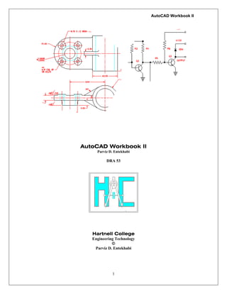
  • 64. AutoCAD Workbook II 64 ROTOR 1. The absolute coordinate value of the center of hole "A" is closest to 2. The perimeter of Rotor is 3. The distance from the center of arc "B" to the center of arc "C" is 4. The absolute coordinate value of the center of arc "D" is closest to 5. The total length of arc "F" is 6. The total area of Rotor with all four holes removed is 7. Change the diameter of all three 1.000 diameter holes to 0.700 diameters. Change the diameter of the 2.550 hole to a new diameter of 1.625. The new area of Rotor with all four holes removed is Figure 33
  • 65. AutoCAD Workbook II 65 Control Bearing Start Point: Center at 11.5, 11.5. 1. The distance from center arc “A” to the intersection at “B” is 2. The total length of arc “C” is 3. The perimeter of inner slot “G” is 4. The absolute coordinate value of the center of the 0.44 diameter hole “F” is 5. The perimeter of the outmost shape of the Control Bearing is 6. The angled formed the XY plane from the intersection at “D” to the center of the arc “E” is 7. The area of the Control Bearing with all holes and inner slot removed is Figure 34
  • 66. AutoCAD Workbook II 66 Additional problems Figure 35