Induction Motor Tests
•
0 likes•232 views

Performing IM tests ; dc test , blocked rotor test & no-load test , to determine the parameters of induction machine.

Recommended
More Related Content
What's hot
What's hot (20)
Similar to Induction Motor Tests
Similar to Induction Motor Tests (20)
More from Hussein Kassem
Recently uploaded
Recently uploaded (20)
Induction Motor Tests
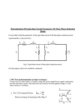
- 1. i. DC Test of determination of stator resistance Connect any two stator leads to a variable-voltage DC power supply.Power supply is adjusted to provide rated stator current. Then determine the resistance from the applied voltage VDC and stator current IDC as follows.
- 2. Then, the AC resistance is given by: R 1=1.15 RDC ii. Blocked-Rotor Test From the DC test, determine R2 when combined with data. The rotor is blocked so that it will not turn. A variable-voltage AC supply is connected and adjust the supply voltage until the blocked-rotor current is equal to the rated current. Neglect the exciting current under blocked-rotor conditions to remove the shunt parameters of equivalent circuit. Finally determine X1 and X2. blocked rotor
- 3. iii. No-Load Test The rotor is allowed to run freely under no-load condition at rated voltage and rated frequency. At no- load condition, the speed is very close to synchronous speed and the slip =0, causing the current in R2/s to be very small, and will be ignored in the calculations. Determine the magnetizing reactance, XM and friction, combined core and windage losses.