Transformer
•Download as DOCX, PDF•
7 likes•633 views

A study of Transformer - e world, electrical basics, electrical world, hazards in transformer, ilektech, transformer, transformer parts, transformer protection

Recommended
More Related Content
What's hot
What's hot (20)
Similar to Transformer
Similar to Transformer (20)
More from Sarin S Abraham
Recently uploaded
Recently uploaded (20)
Transformer
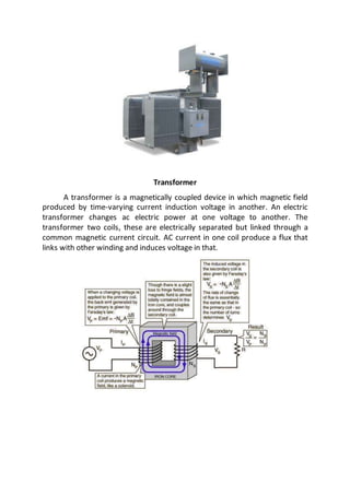
- 1. Transformer A transformer is a magnetically coupled device in which magnetic field produced by time-varying current induction voltage in another. An electric transformer changes ac electric power at one voltage to another. The transformer two coils, these are electrically separated but linked through a common magnetic current circuit. AC current in one coil produce a flux that links with other winding and induces voltage in that.
- 2. STANDARD TRANSFORMER ACCESSORIES 1) Thermometer Pockets This pocket is provided to measure temperature of the top oil in tank with mercury in glass type thermometer. It is essential to fill the pocket with transformer oil before inserting the thermometer, to have uniform and correct reading 2) Buchholz relay A Buchholz relay is a safety device mounted on some oil-filled power transformers and reactors, equipped with an external overhead oil reservoir called a "conservator". The Buchholz relay is used as a protective device sensitive to the effects of dielectric failure inside the equipment. A generic designation for this type of device is "gas detector relay 3) Silica gel breather During the breathing process, the incoming air may consist of moisture and dirt which should be removed in order to prevent any damage. Hence the air is made to pass through the silica gel breather, which will absorb the moisture in the air and ensures that only dry air enters in to the transformer. Silica gel in the breather will be blue when installed and they turn to pink colour when they absorb moisture which indicates the crystals should be replaced. These breathers also have an oil cup fitted with, so that the dust particles get settled in the cup. 4) Air release plug Air release plug is normally provided on the tank cover for transformer with conservator. Space is provided in the plug which allows air to be escaped without removing the plug fully from the seat. Plug should be unscrewed till air comes out from cross hole and as soon as oil flows out it should be closed. Air release plugs are also provided on radiator headers and outdoor bushings. 5) Winding temperature Indicator The windings temperature indicator indicates ‘Hot spot’ temperature of the winding. This is a ‘Thermal Image type’ indicator. This is basically an oil temperature indicator with a heater responsible to raise the temperature equal to the ‘’Hot spot’’ gradient between winding and oil over the oil temperature. Heater coil is fed with a current proportional to the windings current through a current transformer mounted on the winding under measurement it has maximum pointer and re setting device and two sets of contacts for alarm and trip. 6) Oil Temperature Indicator Oil temperature indicator provides local temperature of top oil. Instruments are provided with temperature sensing bulb, temperature recording dial with the pointer and maximum reading pointer and resetting device. Electrical contacts are provided to give alarm or trip at a required setting (on capillary tube type thermometer). 7) Conservator tank It is an Expansion Vessel. It maintains oil in the Transformer above a Minimum Level. It has a Magnetic Oil Level Gage. It can give an alarm if the
- 3. oil level falls below the limit. A portion of the Tank is separated for use with OLTC. This usually has oil level indicators. Main Conservator Tank can have a Bellow. It has an oil filling provision. It has an oil drain valve. Provision is there for connecting a breather 8) Off Load Tap Changer (OLTC) To change the turn’s ratio on the source winding, a switch is operated by a hand wheel on the exterior of the tank. The hand wheel is used to operate a switch within the tank via an exterior operating rod and interior insulated operating rods. The switch takes the form of fixed terminals or contacts arranged in a circle. Turning the hand wheel moves the contact or finger around the center of the circle to complete the circuit and give the desired ratio. This is known as changing tap positions and is performed with the transformer off potential since these switches cannot open a circuit carrying current. 9) Under Load Tap Changer (ULTC) To respond to changing voltage levels on the load side of the transformer is accomplished by adjusting the transformers turns ratios. The under load tap changer switch is designed to change the tapped windings while carrying load current. It is normally operated by a motor and can be operated by hand. The tap changer can be located electrically in the low voltage winding or electrically in the neutral end of the high voltage winding. The motor and control cabinet for the tap changer is located on the side of the transformer 10) Bushings The electrical power circuits must be insulated where they enter the tank. A bushing provides an insulated oil-tight and weather-tight entrance for the conductor into the transformer. It is usually composed of an outer porcelain body, and at higher voltages, additional insulation in the form of oil and wound paper is used within the porcelain column 11) Transformer Cooling In smaller size, liquid-filled types of transformers, natural convection carries the heat of the insulating medium to the walls of the tank. As the size of the transformer increases so does the heat generated, additional means of cooling the transformer are required - Radiator, Fans and Pumps 12) Explosion Vent When an electrical fault occurs under oil, very high pressures are possible. These pressures could readily burst the sheet steel tank if some means were not used to guard against this. The explosion vent consists of a large diameter pipe (4 inches or larger) extending slightly above the conservator tank of the transformer and curved in the direction of the ground. A diaphragm is fitted at the end of the pipe; it will rupture at a relatively low pressure to release the forces from within the transformer to atmosphere. On some transformers, a second diaphragm is located at the bottom of the pipe where the explosion vents connects to the transformer tank. This prevents oil from entering the explosion vent except under fault pressure
- 4. Losses in Transformer The distribution transformers are98% efficient. The efficiency of a transformer depends as follows 1) Copper loss (winding loss) The copper loss is due to current flowing through the windings. When current flow the windings causes resistive heating. (Frequencies, skin effect and proximity effects are also creates additional losses) 2) Core loss (Iron loss) They are of two types a) Hysteresis loss Each time the magnetic field is reversed, a small amount of energy is lost due to hysteresis within the core. For a given core material, the transformer losses are proportional to the frequency, and is a function of the peak flux density to which it is subjected. b) Eddy current loss Eddy currents (also called Foucault currents) are loops of electrical current induced within conductors by a changing magnetic field in the conductor, due to Faraday's law of induction. Eddy currents flow in closed loops within conductors, in planes perpendicular to the magnetic field
- 5. Hazards Associated with a Transformer A transformer is connected to an electrical source and current flows through the transformer. There is some hidden danger in transformer Electrical contact – resulting in electric shock, burns Equipment failure resulting explosions and fire Flashover due to insulation break down Contact Component failure Mechanical failure – Components with moving gears and parts Oil Leaks - Oil/Liquid filled transformers provide insulation and cooling Transformer protection To eliminate and control electrical hazards the transformer must be isolated and de- energized for work on or near it. In addition, work methods are used to control hazards • Lightning Arrestors on HV & LV for Surge Protection • HV / LV Over Current protection • Earth Fault Protection • HG Fuse Protection for Small Capacity Transformers. • horn Gap fuse, used in 11kV & 33kV circuits to disconnect in case of fault • Normally each Power Transformers will have a LV circuit breaker. For a group of transformers up to 5 MVA in a substation a group control circuit breaker is provided. Each transformer of 8 MVA and above will have a circuit breaker on the HV side