
Recommended
More Related Content
Similar to Transformers pptxx.ppt
Similar to Transformers pptxx.ppt (20)
Recently uploaded
Recently uploaded (20)
Transformers pptxx.ppt
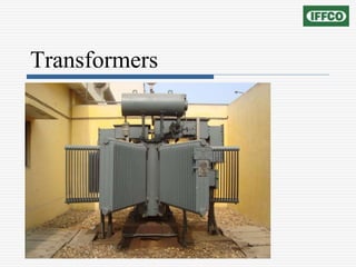
- 1. Transformers
- 2. Topics to be covered… Introduction / Basics Operating Principle Classifications of transformer Construction Transformers parts Losses in transformer Efficiency Parallel operation Maintenance
- 3. Topics to be covered… Testing Protection 3 phase connections / vector groups Transformers in IFFCO Kalol plant Frequently asked questions
- 4. Introduction A transformer is a device that converts ac electric energy at one voltage level to ac electric energy at another voltage level at same frequency. It consists of one or more coil(s) of wire wrapped around a common ferromagnetic core. These coils are usually not connected electrically together. However, they are connected through the common magnetic flux confined to the core. (Mutual Flux)
- 5. Introduction Assuming that the transformer has at least two windings, one of them (primary) is connected to a source of AC power; the other (secondary) is connected to the loads.
- 7. Operating Principle It is based on principle of mutual induction, according to which an e.m.f. is induced in a coil when current in the neighbouring coil changes.
- 8. Classification of Transformers based upon Number of Phases • Single Phase Transformers • Poly-Phase Transformers based on construction based on Function • Step up transformer • Step down transformer (Distribution transformer )
- 9. Instrument transformers • Current transformers • Potential transformers Welding transformers Classification of Transformers
- 10. based on Type of cooling based on location • Indoor transformer • Outdoor transformer Classification of Transformers
- 11. Construction Shell type Windings are wrapped around the centre leg of a laminated core.
- 12. Construction Core type Windings are wrapped around two sides of a laminated square core.
- 13. Construction
- 14. Some Constructional Facts The basic transformer is formed from two coils that are usually wound on a common core to provide a path for the magnetic field lines. The cores of transformers are laminated in order to reduce eddy current losses. These laminations are made of transformer grade steel containing 3-5% silicon, which increases the resistivity of the core, thereby reducing the eddy current core loss.
- 15. The steel used for transformer core is generally cold rolled grain oriented steel as it has the maximum permeability and minimum specific iron loss. The joints at the junctions of different strips of lamination introduce air gaps which result in increased magnetizing current. To reduce the effective air gap, joints in adjacent laminations are overlapped. Some Constructional Facts
- 16. Direction of Windings The direction of the windings determines the polarity of the voltage across the secondary winding with respect to the voltage across the primary. Phase dots are sometimes used to indicate polarities.
- 18. Conservator • It is an Expansion vessel. • It maintains oil in the Transformer above a Minimum level. • It has a Magnetic Oil Level Gage. • It can give an alarm if the oil level falls below the limit. Transformers parts
- 19. • This usually has oil level indicators • Main Conservator Tank can have a Bellow • It has an oil filling provision • It has an oil drain valve • Provision is there for connecting a Breather Transformers parts
- 20. Buchholz Relay • The purpose of such devices is to disconnect faulty apparatus before large scale damage caused by a fault to the apparatus or to other connected apparatus. • Such devices generally respond to a change in the current or pressure arising from the faults and are used for either signalling or tripping the circuits. Transformers parts
- 21. Buchholz Relay • In the event of fault in an oil filled transformer gas is generated, due to which Buchholz relay gives warning of developing fault. • Buchholz relay is provided with two elements one for minor faults (gives alarm) and other for major faults (tripping). The alarm elements operate after a specific volume gets accumulated in the relay. Transformers parts
- 23. Transformers parts Breather • Prevents Moisture Ingress. • Connected to Conservator Tank • Silica Gel is Blue when Dry; Pink when moist • Oil Seal provides a Trap for moisture before passing through silica Gel
- 24. WTI OTI Radiator MOG Marshaling box Tap changer Transformers parts
- 25. Losses in transformer Core loss or Iron loss (Pi) It is the sum of hysteresis (Ph) and eddy current (Pe) loss. It is constant for a machine. 1. Eddy Current Loss where, Ke = proportionality constant f = frequency Bm = maximum flux density in the core 2. Hysteresis Loss where, Kh = proportionality constant x = Steinmetz constant : varies from 1.6 to 2.5
- 26. Copper Losses Also known as losses Cu loss = Primary winding Cu loss + Secondary winding Cu loss Losses in transformer
- 27. Efficiency of transformer Efficiency 100 * 2 2 2 2 2 2 Cos I V Losses Cos I V
- 28. Maximum Transformer Efficiency The efficiency varies as with respect to two independent quantities namely, current and power factor. Thus at any particular power factor, the efficiency is maximum if core loss = copper loss .This can be obtained by differentiating the expression of efficiency with respect to I2 assuming power factor, and all the voltages constant.
- 29. At any particular I2 maximum efficiency happens at unity power factor. This can be obtained by differentiating the expression of efficiency with respect to power factor, and assuming I2 and all the voltages constant. Maximum efficiency happens when both these conditions are satisfied. Maximum Transformer Efficiency
- 30. 100 0 % full load current pf=1 pf= 0.8 pf= 0.6 At this load current core loss = copper loss Maximum efficiency point Maximum Transformer Efficiency
- 31. Parallel operation of transformers The polarities of the transformers must be same. Identical primary and secondary voltage ratings. Impedances inversely proportional to the kVA ratings. Identical X/R ratios in the transformer impedances. The phase sequence must be same. The phase shift between primary and secondary voltages must be the same for all transformers which are to be connected in parallel.
- 32. Maintenance of transformers Inspection of primary and secondary cable boxes, end termination, checking and tightening of connections. Recommended Tests & Measurement of parameters like Insulation resistance, BDV of transformer oil are carried out on each transformer. Alarm & tripping contacts of Buchholz relay and MOG are checked.
- 33. Condition of silica gel is checked. Accordingly discharged silica gel is recharged. Oil leakages from the transformers are attended and damaged gaskets are replaced Maintenance of transformers
- 34. Testing of transformer Routine tests The routine tests are conducted to ensure the particular transformer is free from manufacturing defects. ( To be carried out on each job) • Measurement of winding resistance • Measurement of insulation resistance • Separate source voltage withstand test (high voltage tests on HV & LV)
- 35. • HV high voltage test : LV winding connected together and earthed. HV winding connected together and given 28 KV ( for 11KV transformer) for 1 minute. • LV high voltage test : hv winding connected together and earthed. LV winding connected together and given 3 KV for 1 minute. • Induced over voltage withstand test (DVDF test) for a 11KV/433V transformer,866 volts are applied at the 433V winding with the help of a generator for 1 minute. This induces 22KV on 11KV side. The frequency of the 866V supply is also increased to 100HZ. Testing of transformer
- 36. • Measurement of voltage ratio • Measurement of no load loss & current. • Measurement of load loss & impedance.(Efficiency & regulation) • Vector group verification • Oil BDV test. • Tests on OLTC (if attached) Testing of transformer
- 37. Vector group Dyn11 verification RY=Rn+Yn (400=7+393) Yy=Yb (388=389) By>Bb (399>389) Testing of transformer
- 38. Type test The type tests are conducted to check the particular design parameters. • Lightening Impulse test. • Temperature rise test Testing of transformer
- 39. Special tests The special tests are conducted depending upon the need for particular test-as per site conditions. The special tests have to be agreed between the purchaser and supplier. Hence purchaser should clearly specify conducting special tests in the P.O. • Dynamic short circuit test • Measurement of Zero sequence impedance Testing of transformer
- 40. • Measurement of harmonics • Partial discharge measurement • Measurement of tan delta • Measurement of noise level Testing of transformer
- 41. Protection of transformer The best way of protecting a transformer is to have good preventive maintenance schedule. Oil Temperature Indicators. Winding Temperature indicators. Buchholz Relay. Magnetic Oil level Gauge. Explosion Vent.
- 42. HT fuse & D.O. fuse. LT circuit breaker. HT Circuit breaker with Over load, Earth Fault relay tripping. PRV for OLTC Breather Fire push button Protection of transformer
- 44. 3 phase connections / vector groups There are many combinations in which HV and LV windings of transformers employed in 3-phase systems may be connected. 3-phase transformers are divided into four main groups according to the phase difference between the corresponding line voltages on the HV and LV sides.
- 45. 3 phase connections / vector groups
- 46. 3 phase connections / vector groups
- 47. 3 phase connections / vector groups
- 48. 3 phase connections / vector groups
- 49. 3 phase connections / vector groups
- 50. 3 phase connections / vector groups
- 51. Delta-delta connection 3 phase connections / vector groups
- 52. Star - star connection 3 phase connections / vector groups
- 53. Delta-star connection 3 phase connections / vector groups
- 54. Star-delta connection 3 phase connections / vector groups
- 57. Frequently asked questions Why transformer ratings in kva Why transformer does not rotate Operation of transformer when applied DC Why tap changer on HV side
- 58. Any query? •If any mistake or wrong information given here, please rectify/correct me.
- 60. Break time!