
Recommended
More Related Content
Similar to power transforer.pptx
Similar to power transforer.pptx (20)
Recently uploaded
Recently uploaded (20)
power transforer.pptx
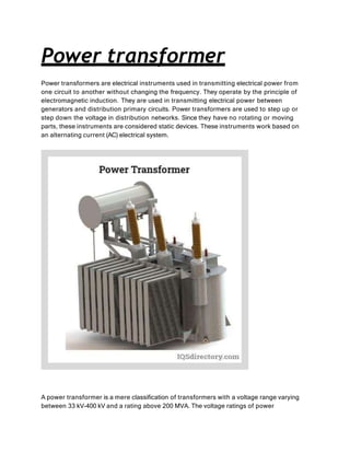
- 1. Power transformer Power transformers are electrical instruments used in transmitting electrical power from one circuit to another without changing the frequency. They operate by the principle of electromagnetic induction. They are used in transmitting electrical power between generators and distribution primary circuits. Power transformers are used to step up or step down the voltage in distribution networks. Since they have no rotating or moving parts, these instruments are considered static devices. These instruments work based on an alternating current (AC) electrical system. A power transformer is a mere classification of transformers with a voltage range varying between 33 kV-400 kV and a rating above 200 MVA. The voltage ratings of power
- 2. transformers available in the market include 400 kV, 200 kV, 110 kV, 66 kV, and 33 kV. The other types of transformers include distribution (230 V-11kV) and instrument transformers. Power transformers are essential in minimizing substantial energy losses, due to Joule’s effect, in the transmission of large amounts of electrical power over long distances by converting it into high-voltage current then stepping it down to a safer low-voltage current. They are commonly found in power plants, industrial plants, and electric utility companies. Operating Principle of Power Transformers Faraday’s Law of Electromagnetic Induction Power transformers operate based on Faraday’s law of electromagnetic induction. This law is the working principle of all transformers, inductors, motors, generators, and solenoids. Faraday’s law states that when a closed-loop is brought near a fluctuating magnetic field, an electromotive force (emf) will be induced across it. When alternating current is allowed to flow through a coil, an alternating or fluctuating magnetic flux surrounds the coil (primary winding). The magnetic flux produced by the primary winding passes through a ferromagnetic core to be transmitted effectively to a secondary winding. The magnetic flux will then induce an emf in the secondary winding
- 3. due to electromagnetic induction. The induced emf will stimulate the flow of current in the secondary winding. Stepping Voltages Up or Down The total voltage in a winding is equal to the voltage per turn of the coil multiplied by the number of turns. Since the voltage per turn of the primary and secondary windings are the same, the induced voltage in the secondary winding can be related to the input voltage on the primary winding. This relationship is expressed by the equation: Vs = Vp/Np x Ns Where V represents the total voltage in the winding, N represents the number of turns of a winding, and the subscripts p and s refer to the primary and secondary windings, respectively. The ratio of the number of turns in the secondary winding to that of the primary winding (Ns/Np) is called the turns ratio. If the number of turns in the secondary winding is fewer than the number of turns in the primary winding, the voltage output is lower than the input voltage (step-down transformer). On the other hand, if the number of turns in the secondary winding is more than the number of turns in the primary winding, the voltage output is higher than the input voltage (step-up transformer).
- 4. Since energy is conserved, the relationship between the alternating current in the primary and secondary windings is represented by the below equation: Vp Ip = Vs Is Where I represents the current. Components of Power Transformers The basic parts of transformers are the core and the primary and secondary windings, which are discussed in more detail in this chapter. Core Components The core supports the windings and provides a low reluctance path for the magnetic flux. It is made by stacking and laminating thin steel sheets. The sheets are insulated from each other by a coating. To reduce eddy current losses and hysteresis losses, the iron or steel sheets are less than one millimeter thick, and their carbon content is maintained below 0.1%. Eddy current is further reduced by alloying the steel with silicon. The vertical sections of the core in which the windings are carried are r
- 5. eferred to as the limbs, while the horizontal sections of the core that couples the limbs are referred to as the yokes. Windings in Power Transformers The windings are made up of copper or aluminum conductor coil with a specific number of turns. Copper is the preferred material since it offers high electrical conductivity and high ductility; these properties reduce the amount of winding and make the material easier to wrap around the core. A transformer consists of at least two windings- the primary and the secondary windings. The primary winding is the winding in which the input voltage is applied, while the secondary winding is the winding that receives the output voltage. The primary and the secondary windings in a phase of a transformer can play as the high voltage (HV) winding or the low voltage (LV) winding: HV Winding The HV winding has a greater number of turns and consists of a thinner conductor than the LV winding.
- 6. LV Winding The LVwinding has a fewer number of turns. It consists of a thicker conductor than the HV winding since a higher current is carried in the LV winding. Other parts of power transformers include the following: Insulating Materials Insulating materials are used to isolate the windings from the core, the primary and the secondary windings, and each turn of the windings. These materials protect the transformer from damage. Transformer insulators should have high dielectric strength, good mechanical properties, and can withstand high temperatures. Paper and pressboard can be used as an insulator (i.e., dry-type transformers); however, they have limited service lives and require frequent replacement as these materials can degrade. Hence, transformer oils are more common compared to solid insulating materials. They provide enhanced insulation between conducting parts, act as a coolant for the coil and windings assembly, and have fault detection features. Hydrocarbon mineral oils consisting of aromatics, paraffin, naphthene, and olefins are used as transformer oils. Oil contamination must be prevented to preserve the oil’s dielectric properties and insulating features. Tap Changer Tap changers are devices that regulate the transformer’s output voltage as it responds accordingly to the varying input voltage and load by adjusting the number of turns in one winding. This adjustment, therefore, changes the turn ratio. During offloading conditions, the output voltage increases, whereas during loaded conditions, the output voltage decreases. Tap changers are typically connected in the HV winding to make fine voltage regulations and minimize core losses of the transformer. The current is also lower in the HV winding, which minimizes the risk of sparking and igniting the transformer oil. There are two types of tap changers. Onload tap changers are designed to tap the voltage without disrupting the current flow to the load. Whereas offload tap changers require disconnecting the load of the transformer before operating.
- 7. Bushings in Transformers Bushings are insulated barriers that contain the terminal that connects the current-carrying conductor from an electrical network to the ends of the transformer windings. The bushing insulation is typically made from porcelain or epoxy resin. The bushings are mounted over the main tank.
- 8. Transformer Tank The transformer tank (or the main tank) houses and protects the core, windings, and other components from the external environment. It serves as the container for the transformer oil. It is constructed from rolled steel plates or aluminum sheets. The following are present in large transformers insulated with hydrocarbon mineral oil:
- 9. Conservator Component The conservator is a tank that serves as the reservoir of the transformer oil and is located above the main tank and bushings. Transformer oil from the conservator is supplied to the main oil tank inside the transformer through a pipeline. The conservator has a flexible bladder that allows the expansion and contraction of the oil. It has an adequate space to allow the expansion of the oil during high ambient temperatures. The conservator is vented to the atmosphere to balance the pressure changes during the expansion and contraction of the oil by intaking or releasing air. Breather Component The breather delivers moisture-free air to the conservator by passing air through a small bed of silica gel inside a cylindrical container. The silica gel acts as an air filter that strips and controls the moisture level inside the conservator and the main tank. The breather is connected by a pipeline to the conservator. Moisture can degrade the insulating properties of the transformer oil or may even lead to internal faults. Therefore, it is necessary to remove the moisture.
- 10. Cooling System The cooling system is a critical component of transformers regardless of the insulating material utilized. Power losses occurring in the transformers are in the form of heat increasing the temperature of the windings and the core. Consequently, the temperature of the insulating material will also increase. Without a cooling system, these components may be damaged or decomposed if heated continually. The cooling system of transformers consists of fans, radiators, and cooling tubes. Heat transfer mechanism occurs by natural and/or forced convection and radiation. For dry-type transformers, cooling may be accomplished by the following methods: Air Natural Air Forced For oil-immersed type transformers, cooling may be accomplished by the following methods: Oil Natural Air Natural Oil Natural Air Forced Oil Forced Air Forced Oil Natural Water Forced Oil Forced Water Forced Explosion Vent The explosion vent is a metallic pipe with a diaphragm at its free end located slightly above the conservator tank. It releases gases, transformer oil, and energy during internal faults to relieve the excessive pressure inside the transformer, thus preventing the explosion of the transformer. Faults elevate the internal pressure of the transformer to dangerous levels. When such circumstances occur, energy will be released into the atmosphere, destroying the diaphragm at relatively low pressure. Buchholz Relay The Buchholz relay is a device installed along the pipeline connecting the conservator and the main tank. It detects faults in the transformer by sensing the emitted gases to activate the trip and alarm circuits. Once the trip circuit is activated, the circuit breaker will then disrupt the current flow to the primary winding. Emitted gases are generated by the heat released induced by faults.