SlideShare a Scribd company logo
1 of 14
1 Light enters a glass block at an angle of incidence i and it produces an angle of refraction r in the
glass.
glass
block
r
i
Several different values of i and r are measured, and a graph is drawn of sin i against sin r.
Which graph is correct?
sin i
sin r
sin i
sin r
sin i
sin r
1.0
0.5
0
0 0.5 1.0
sin i
sin r
A B C D
1.0
0.5
0
0 0.5 1.0
1.0
0.5
0
0 0.5 1.0
1.0
0.5
0
0 0.5 1.0
Beaconhouse School System
Retest- Physics
Class: XIC
Name:
Total marks:65
Objective
2 A swimming pool is lit by an underwater light.
A ray of light is incident on the water surface.
What is the correct path for the ray of light?
water surface
A
B
D
C
light
Total marks: 15
3 Which diagram shows the action of a converging lens on a parallel beam of light?
B
A
D
C
4 What is a feature of red light compared with that of violet light?
A A prism deviates red light more.
B Red light has a lower frequency.
C Red light has a shorter wavelength.
D The speed of red light in a vacuum is smaller.
5 What is the ratio of the longest sound wavelength audible to a healthy human ear to the shortest?
A 20:1 B 1000:1 C 10000:1 D 20000:1
6 Ultrasound is used to clean jewellery in a liquid.
What is another use of ultrasound?
A optical fibre communication
B pre-natal scanning
C sunbeds
D telephone communications
7 Bar magnets and various non-magnetic and demagnetised metal bars are placed in the different
arrangements shown.
In which arrangement do the bars repel?
N
A
S
N
C
S
S
N N
D
S S
N
iron N
B
S copper
8 The diagram shows how the height above the ground of a rope transmitting a wave varies with
distance from the source of vibrations at one instant in time.
80
60
40
20
0
height above
ground/cm
0 0
2 0
4 0
6 120
What is the amplitude of the wave shown?
A 30cm B 34cm C 72cm
80 100
distance from source/cm
D 74cm
9 A vibrator produces 12 wavelengths on the surface of water in 10s. The spacing between the first
crest and the third crest is 60cm.
What is the speed of the wave?
A 24cm/s B 25cm/s C 36cm/s D 72cm/s
10 There is varying current in the coil of the loudspeaker shown. The loudspeaker is producing a
sound. The magnet is clamped.
coil
magnet
clamp
cone
What is vibrating to produce the sound?
A coil only
B cone only
C magnet only
D coil and cone
11 Two insulated and uncharged metal spheres X and Y are touching.
A positively charged rod is held near X and then the spheres are moved apart.
X now has a negative charge.
X Y
+
+
+
What is the charge on Y?
A negative and smaller than that on X
B negative and the same size as that on X
C positive and smaller than that on X
D positive and the same size as that on X
12 A stationary negative charge in an electric field experiences an electric force in the direction
shown.
force
left right
–
What is the direction of the electric field?
A to the left
B to the right
C down the page
D up the page
13 A battery consists of three identical cells in parallel.
What is the unit of electromotive force (e.m.f.) and to what is the e.m.f. of the battery equal?
unit e.m.f. of the battery is equal to
A J/C the sum of the e.m.f.s of the three cells
B J/C the e.m.f. of one of the cells
C N/V the sum of the e.m.f.s of the three cells
D N/V the e.m.f. of one of the cells
14 A metal wire of length l and cross-sectional area A has resistance R.
2
A second wire is made from the same metal. It has a length 2l and a cross-sectional area 4A.
What is the resistance of the second wire?
A 8R B 2R C R D R
8
15 A rectangular current-carrying coil is pivoted between the poles of an electromagnet.
Which action does not, on its own, increase the size of the turning effect exerted on the coil?
A increasing the current in the coils of the electromagnet
B increasing the current in the rectangular coil
C reversing the current in the electromagnet
D increasing the number of turns on the rectangular coil
1 Fig. 8.1 shows a lamp from a car. It contains two metal filaments.
filament 1
filament 2
Fig. 8.1
(a) (i) Complete the boxes to describe the transfer of energy that takes place when the lamp is
switched on.
........................ energy .................................. and .................................. energy
[3]
(ii) The efficiency of the metal filament lamp is less than 10%.
State what is meant by efficiency.
...........................................................................................................................................
..................................................................................................................................... [2]
(b) The two filaments are usually connected in parallel to a car battery.
A student investigates what happens when the filaments are connected in series, rather than
in parallel. He uses the same battery for the investigation.
State whether the current, the voltage across each filament and the total power produced
increases, decreases or stays the same when the two filaments are connected in series.
current ...............................................................................................
voltage ...............................................................................................
power ................................................................................................
[2]
Subjective
Total marks:330
(c) Fig. 8.2 shows the current–voltage graph for the two filaments.
0
0
0.5
1.0
1.5
2.0
2.0 4.0 6.0 8.0 10.0
voltage/V
current/A
12.0
Fig. 8.2
(i) Calculate the total resistance of the two filaments when they are connected in parallel to
a voltage of 12V.
resistance = ......................................................... [3]
(ii) The two filaments are made from the same type of metal and have the same length,
when uncoiled. They both operate at the same temperature.
Suggest why one filament has a resistance that is greater than that of the other filament.
...........................................................................................................................................
..................................................................................................................................... [1]
(d) Fig. 8.3 shows a relay used to switch on a car headlamp.
pivot
S
H
iron armature
flexible contacts
iron core
coil of high resistance
relay
Fig. 8.3
Explain why headlamp H lights up when switch S is closed.
...................................................................................................................................................
...................................................................................................................................................
...................................................................................................................................................
...................................................................................................................................................
...................................................................................................................................................
............................................................................................................................................. [4]
[Total: 15]
2 Ultrasound and X-rays are both used in medical imaging.
(a) (i) Define what is meant by ultrasound.
...........................................................................................................................................
..................................................................................................................................... [2]
(ii) Describe what happens to ultrasound waves as they meet the boundary between two
different materials.
...........................................................................................................................................
..................................................................................................................................... [2]
(iii) To produce the image of an unborn child, an ultrasound emitter and receiver are placed
close together on the mother’s skin.
Fig. 9.1 shows pulses detected by the receiver.
0 0.02 0.04 0.06 0.08
A
B
time/ms
Fig. 9.1
Pulse A is the emitted pulse and pulse B is the first pulse that returns from the unborn child.
The average speed of ultrasound in human tissue is 1500m/s.
Calculate the distance between the emitter and the child.
distance = ......................................................... [3]
(iv) The speed of ultrasound in human tissue is close to the speed of sound in water.
Suggest approximate values for the speed of sound in gases and solids.
speed in gases ..................................................................................................................
speed in solids ..................................................................................................................
[2]
(b) Fig. 9.2 shows an X-ray image of a hand. An X-ray detector is placed just below the hand.
An image of the bones and human tissue around the bones is formed on a screen by the
detector.
screen
Fig. 9.2
(i) Describe what happens to the X-rays to produce the image.
...........................................................................................................................................
...........................................................................................................................................
...........................................................................................................................................
...........................................................................................................................................
..................................................................................................................................... [3]
(ii) The wavelength of the X-rays used is 2.0 × 10⁻⁹ m. The speed of electromagnetic waves
is 3.0 × 10⁸ m/s.
Calculate the frequency of the X-rays.
frequency = ......................................................... [2]
(iii) Suggest one reason why X-rays are not used to form an image of an unborn child.
...........................................................................................................................................
..................................................................................................................................... [1]
[Total: 15]
3 A student investigates the effective resistance of different combinations of three identical resistors.
She sets up circuit 1, shown in Fig. 3.1.
circuit 1
Y
X
A
V
Fig. 3.1
She measures and records the current I in the circuit and the potential difference V across the
resistor combination.
Fig. 3.2 shows part of the scale of the voltmeter.
1.5
1.4
V
Fig. 3.2
(a) Read the voltmeter scale shown in Fig. 3.2. Record your answer on the answer line and in
Table 3.1 on page 8.
voltmeter reading = ...................................................... V [1]
ATP
Total marks:
(b) The student uses two more combinations of the three resistors. The combinations are shown
in Fig. 3.3.
circuit 2 circuit 3
Fig. 3.3
She replaces the resistor combination shown between X and Y in circuit 1 with that of circuit 2
and then that of circuit 3, in turn.
Each time she records the current I in the circuit and the potential difference V across the
resistor combination.
Her results are shown in Table 3.1.
Table 3.1
circuit V/............... I/............... R/...............
1 0.13
2 1.46 0.25
3 1.46 0.58
The resistance R of each combination of resistors is given by
R = V/I
[3]
(i) Complete the column headings in Table 3.1.
(ii) Calculate the resistance R of each combination of resistors.
Record the values of R in Table 3.1. [4]
(c) Theory suggests that for identical resistors, the resistance of the resistor combination in
circuit 1 is double the resistance of the resistor combination in circuit 2.
State whether your results support this theory, within the limits of experimental accuracy. Give
a reason for your answer.
...................................................................................................................................................
............................................................................................................................................. [1]
(d) Give one precaution that the student takes so that her readings of current and voltage are as
accurate as possible.
...................................................................................................................................................
............................................................................................................................................. [1]
[Total: 10]
3 A student investigates how the resistance of a filament lamp changes as the potential difference V
across it changes. He uses the circuit shown in Fig. 3.1.
Fig. 3.1
(a) On Fig. 3.1, draw the symbol for an ammeter and the symbol for a voltmeter in the correct
positions for this investigation. [2]
(b) The student takes two different sets of readings of current and potential difference.
(i) Suggest how he adjusts his circuit to do this.
...........................................................................................................................................
..................................................................................................................................... [2]
(ii) He adjusts his circuit so that the voltmeter shows 4.0V and he reads the ammeter. He
repeats the experiment at 8.0V.
Fig. 3.2 shows the readings of current I on the ammeter for each voltage.
0
0.50 1.50
2.0
1.0
A
+
when V = 4.0V
0
0.50 1.50
2.0
1.0
A
+
when V = 8.0V
Fig. 3.2
Record the values of I shown on the meter for each voltage.
When V is 4.0V, I = ............................................................ A
When V is 8.0V, I = ............................................................ A [2]
(iii) Use the equation:
V
I
R =
to calculate the resistance R of the lamp at 4.0V and at 8.0V.
State the unit in your answers.
V is 4.0V, R =
When ...............................................................
V is 8.0V, R =
When ...............................................................
[2]
(c) State two physical changes in the lamp that are observed as the potential difference V is
increased.
1 ................................................................................................................................................
...................................................................................................................................................
2 ................................................................................................................................................
...................................................................................................................................................
[2]
[Total: 10]

More Related Content

What's hot

L13 magnetic induction
L13   magnetic inductionL13   magnetic induction
L13 magnetic induction
Satyakam
 
Electromagnetic Induction Class 12
Electromagnetic Induction Class 12 Electromagnetic Induction Class 12
Electromagnetic Induction Class 12
Self-employed
 
faradays law and its applications ppt
faradays law and its applications pptfaradays law and its applications ppt
faradays law and its applications ppt
Indira Kundu
 
Ap physics b_-_electromagnetic_induction
Ap physics b_-_electromagnetic_inductionAp physics b_-_electromagnetic_induction
Ap physics b_-_electromagnetic_induction
Jeremy Walls
 

What's hot (19)

Electromagnetic Induction
Electromagnetic InductionElectromagnetic Induction
Electromagnetic Induction
 
Electromagnetic induction 2
Electromagnetic induction 2Electromagnetic induction 2
Electromagnetic induction 2
 
L13 magnetic induction
L13   magnetic inductionL13   magnetic induction
L13 magnetic induction
 
Electromagnetic induction
Electromagnetic inductionElectromagnetic induction
Electromagnetic induction
 
Electromagnetic Induction
Electromagnetic InductionElectromagnetic Induction
Electromagnetic Induction
 
Electromagnetic induction
Electromagnetic induction Electromagnetic induction
Electromagnetic induction
 
Electromagnetic Induction Class 12
Electromagnetic Induction Class 12 Electromagnetic Induction Class 12
Electromagnetic Induction Class 12
 
Magnetic effect of electric current
Magnetic effect of electric currentMagnetic effect of electric current
Magnetic effect of electric current
 
Electromagnetic induction
Electromagnetic inductionElectromagnetic induction
Electromagnetic induction
 
faradays law and its applications ppt
faradays law and its applications pptfaradays law and its applications ppt
faradays law and its applications ppt
 
Electromagnetic induction
Electromagnetic inductionElectromagnetic induction
Electromagnetic induction
 
Electromagnetic induction
Electromagnetic inductionElectromagnetic induction
Electromagnetic induction
 
Electromagnetic induction and transformer
Electromagnetic induction and transformer Electromagnetic induction and transformer
Electromagnetic induction and transformer
 
Faradays law
Faradays lawFaradays law
Faradays law
 
emi
emiemi
emi
 
Electromagnetic induction
Electromagnetic induction Electromagnetic induction
Electromagnetic induction
 
G 10 electromagmetism lq
G 10 electromagmetism lqG 10 electromagmetism lq
G 10 electromagmetism lq
 
Ap physics b_-_electromagnetic_induction
Ap physics b_-_electromagnetic_inductionAp physics b_-_electromagnetic_induction
Ap physics b_-_electromagnetic_induction
 
Std X Ch5 Electromagnetism
Std X Ch5 ElectromagnetismStd X Ch5 Electromagnetism
Std X Ch5 Electromagnetism
 

Similar to Retest 2022 xic

L10 superconductivity
L10 superconductivityL10 superconductivity
L10 superconductivity
mphilip1
 
13925cbse guess 5
13925cbse guess 513925cbse guess 5
13925cbse guess 5
ashikjose
 
Electronics module
Electronics moduleElectronics module
Electronics module
Ota Keiko
 
Nov 2002 p.2
Nov 2002 p.2Nov 2002 p.2
Nov 2002 p.2
King Ali
 
Cbse class 12 physics sample paper 02 (for 2014)
Cbse class 12 physics sample paper 02 (for 2014)Cbse class 12 physics sample paper 02 (for 2014)
Cbse class 12 physics sample paper 02 (for 2014)
mycbseguide
 

Similar to Retest 2022 xic (20)

Waves q
Waves qWaves q
Waves q
 
Waves q
Waves qWaves q
Waves q
 
Waves q
Waves qWaves q
Waves q
 
XPhysics- etrtrrrrrrrrr I.doc
XPhysics-  etrtrrrrrrrrr           I.docXPhysics-  etrtrrrrrrrrr           I.doc
XPhysics- etrtrrrrrrrrr I.doc
 
L10 superconductivity
L10 superconductivityL10 superconductivity
L10 superconductivity
 
IIT JEE Physics 2006
IIT JEE Physics   2006IIT JEE Physics   2006
IIT JEE Physics 2006
 
Class 12 Cbse Physics Sample Paper 2013 Model 2
Class 12 Cbse Physics Sample Paper 2013 Model 2Class 12 Cbse Physics Sample Paper 2013 Model 2
Class 12 Cbse Physics Sample Paper 2013 Model 2
 
Polarization of light
Polarization of lightPolarization of light
Polarization of light
 
13925cbse guess 5
13925cbse guess 513925cbse guess 5
13925cbse guess 5
 
Physics 22-23.docx
Physics 22-23.docxPhysics 22-23.docx
Physics 22-23.docx
 
Physics sqp
Physics sqpPhysics sqp
Physics sqp
 
Class 12 Cbse Physics Sample Paper 2010 Model 3
Class 12 Cbse Physics Sample Paper 2010 Model 3Class 12 Cbse Physics Sample Paper 2010 Model 3
Class 12 Cbse Physics Sample Paper 2010 Model 3
 
Cbse 12 Class Physics Sample Paper 2010 Model 2
Cbse 12 Class Physics Sample Paper 2010 Model 2Cbse 12 Class Physics Sample Paper 2010 Model 2
Cbse 12 Class Physics Sample Paper 2010 Model 2
 
Electronics module
Electronics moduleElectronics module
Electronics module
 
Nov 2002 p.2
Nov 2002 p.2Nov 2002 p.2
Nov 2002 p.2
 
Physics Sample Paper with General Instruction for Class - 12
Physics Sample Paper with General Instruction for Class - 12Physics Sample Paper with General Instruction for Class - 12
Physics Sample Paper with General Instruction for Class - 12
 
Cbse class 12 physics sample paper 02 (for 2014)
Cbse class 12 physics sample paper 02 (for 2014)Cbse class 12 physics sample paper 02 (for 2014)
Cbse class 12 physics sample paper 02 (for 2014)
 
CBSE Sample Paper 2015 of Class XII Physics
CBSE Sample Paper 2015 of Class XII PhysicsCBSE Sample Paper 2015 of Class XII Physics
CBSE Sample Paper 2015 of Class XII Physics
 
Physics sqp
Physics sqpPhysics sqp
Physics sqp
 
Physics sample question paper 2020
Physics sample question paper 2020 Physics sample question paper 2020
Physics sample question paper 2020
 

Recently uploaded

Electricity and Circuits for Grade 9 students
Electricity and Circuits for Grade 9 studentsElectricity and Circuits for Grade 9 students
Electricity and Circuits for Grade 9 students
levieagacer
 
Heat Units in plant physiology and the importance of Growing Degree days
Heat Units in plant physiology and the importance of Growing Degree daysHeat Units in plant physiology and the importance of Growing Degree days
Heat Units in plant physiology and the importance of Growing Degree days
Brahmesh Reddy B R
 

Recently uploaded (20)

Information science research with large language models: between science and ...
Information science research with large language models: between science and ...Information science research with large language models: between science and ...
Information science research with large language models: between science and ...
 
Vital Signs of Animals Presentation By Aftab Ahmed Rahimoon
Vital Signs of Animals Presentation By Aftab Ahmed RahimoonVital Signs of Animals Presentation By Aftab Ahmed Rahimoon
Vital Signs of Animals Presentation By Aftab Ahmed Rahimoon
 
Film Coated Tablet and Film Coating raw materials.pdf
Film Coated Tablet and Film Coating raw materials.pdfFilm Coated Tablet and Film Coating raw materials.pdf
Film Coated Tablet and Film Coating raw materials.pdf
 
Electricity and Circuits for Grade 9 students
Electricity and Circuits for Grade 9 studentsElectricity and Circuits for Grade 9 students
Electricity and Circuits for Grade 9 students
 
EU START PROJECT. START-Newsletter_Issue_4.pdf
EU START PROJECT. START-Newsletter_Issue_4.pdfEU START PROJECT. START-Newsletter_Issue_4.pdf
EU START PROJECT. START-Newsletter_Issue_4.pdf
 
Costs to heap leach gold ore tailings in Karamoja region of Uganda
Costs to heap leach gold ore tailings in Karamoja region of UgandaCosts to heap leach gold ore tailings in Karamoja region of Uganda
Costs to heap leach gold ore tailings in Karamoja region of Uganda
 
PHOTOSYNTHETIC BACTERIA (OXYGENIC AND ANOXYGENIC)
PHOTOSYNTHETIC BACTERIA  (OXYGENIC AND ANOXYGENIC)PHOTOSYNTHETIC BACTERIA  (OXYGENIC AND ANOXYGENIC)
PHOTOSYNTHETIC BACTERIA (OXYGENIC AND ANOXYGENIC)
 
RACEMIzATION AND ISOMERISATION completed.pptx
RACEMIzATION AND ISOMERISATION completed.pptxRACEMIzATION AND ISOMERISATION completed.pptx
RACEMIzATION AND ISOMERISATION completed.pptx
 
Manganese‐RichSandstonesasanIndicatorofAncientOxic LakeWaterConditionsinGale...
Manganese‐RichSandstonesasanIndicatorofAncientOxic  LakeWaterConditionsinGale...Manganese‐RichSandstonesasanIndicatorofAncientOxic  LakeWaterConditionsinGale...
Manganese‐RichSandstonesasanIndicatorofAncientOxic LakeWaterConditionsinGale...
 
ABHISHEK ANTIBIOTICS PPT MICROBIOLOGY // USES OF ANTIOBIOTICS TYPES OF ANTIB...
ABHISHEK ANTIBIOTICS PPT MICROBIOLOGY  // USES OF ANTIOBIOTICS TYPES OF ANTIB...ABHISHEK ANTIBIOTICS PPT MICROBIOLOGY  // USES OF ANTIOBIOTICS TYPES OF ANTIB...
ABHISHEK ANTIBIOTICS PPT MICROBIOLOGY // USES OF ANTIOBIOTICS TYPES OF ANTIB...
 
POST TRANSCRIPTIONAL GENE SILENCING-AN INTRODUCTION.pptx
POST TRANSCRIPTIONAL GENE SILENCING-AN INTRODUCTION.pptxPOST TRANSCRIPTIONAL GENE SILENCING-AN INTRODUCTION.pptx
POST TRANSCRIPTIONAL GENE SILENCING-AN INTRODUCTION.pptx
 
GBSN - Microbiology (Unit 4) Concept of Asepsis
GBSN - Microbiology (Unit 4) Concept of AsepsisGBSN - Microbiology (Unit 4) Concept of Asepsis
GBSN - Microbiology (Unit 4) Concept of Asepsis
 
Heat Units in plant physiology and the importance of Growing Degree days
Heat Units in plant physiology and the importance of Growing Degree daysHeat Units in plant physiology and the importance of Growing Degree days
Heat Units in plant physiology and the importance of Growing Degree days
 
FORENSIC CHEMISTRY ARSON INVESTIGATION.pdf
FORENSIC CHEMISTRY ARSON INVESTIGATION.pdfFORENSIC CHEMISTRY ARSON INVESTIGATION.pdf
FORENSIC CHEMISTRY ARSON INVESTIGATION.pdf
 
Classification of Kerogen, Perspective on palynofacies in depositional envi...
Classification of Kerogen,  Perspective on palynofacies in depositional  envi...Classification of Kerogen,  Perspective on palynofacies in depositional  envi...
Classification of Kerogen, Perspective on palynofacies in depositional envi...
 
NUMERICAL Proof Of TIme Electron Theory.
NUMERICAL Proof Of TIme Electron Theory.NUMERICAL Proof Of TIme Electron Theory.
NUMERICAL Proof Of TIme Electron Theory.
 
GBSN - Biochemistry (Unit 3) Metabolism
GBSN - Biochemistry (Unit 3) MetabolismGBSN - Biochemistry (Unit 3) Metabolism
GBSN - Biochemistry (Unit 3) Metabolism
 
Polyethylene and its polymerization.pptx
Polyethylene and its polymerization.pptxPolyethylene and its polymerization.pptx
Polyethylene and its polymerization.pptx
 
Mining Activity and Investment Opportunity in Myanmar.pptx
Mining Activity and Investment Opportunity in Myanmar.pptxMining Activity and Investment Opportunity in Myanmar.pptx
Mining Activity and Investment Opportunity in Myanmar.pptx
 
Factor Causing low production and physiology of mamary Gland
Factor Causing low production and physiology of mamary GlandFactor Causing low production and physiology of mamary Gland
Factor Causing low production and physiology of mamary Gland
 

Retest 2022 xic

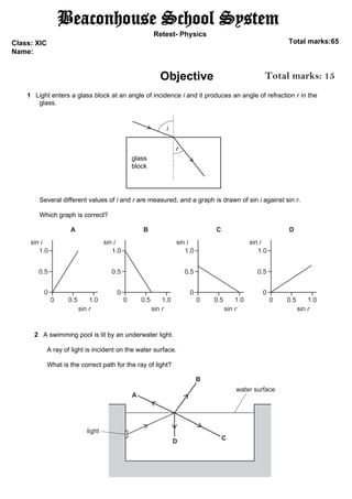
  • 1. 1 Light enters a glass block at an angle of incidence i and it produces an angle of refraction r in the glass. glass block r i Several different values of i and r are measured, and a graph is drawn of sin i against sin r. Which graph is correct? sin i sin r sin i sin r sin i sin r 1.0 0.5 0 0 0.5 1.0 sin i sin r A B C D 1.0 0.5 0 0 0.5 1.0 1.0 0.5 0 0 0.5 1.0 1.0 0.5 0 0 0.5 1.0 Beaconhouse School System Retest- Physics Class: XIC Name: Total marks:65 Objective 2 A swimming pool is lit by an underwater light. A ray of light is incident on the water surface. What is the correct path for the ray of light? water surface A B D C light Total marks: 15
  • 2. 3 Which diagram shows the action of a converging lens on a parallel beam of light? B A D C 4 What is a feature of red light compared with that of violet light? A A prism deviates red light more. B Red light has a lower frequency. C Red light has a shorter wavelength. D The speed of red light in a vacuum is smaller. 5 What is the ratio of the longest sound wavelength audible to a healthy human ear to the shortest? A 20:1 B 1000:1 C 10000:1 D 20000:1 6 Ultrasound is used to clean jewellery in a liquid. What is another use of ultrasound? A optical fibre communication B pre-natal scanning C sunbeds D telephone communications
  • 3. 7 Bar magnets and various non-magnetic and demagnetised metal bars are placed in the different arrangements shown. In which arrangement do the bars repel? N A S N C S S N N D S S N iron N B S copper 8 The diagram shows how the height above the ground of a rope transmitting a wave varies with distance from the source of vibrations at one instant in time. 80 60 40 20 0 height above ground/cm 0 0 2 0 4 0 6 120 What is the amplitude of the wave shown? A 30cm B 34cm C 72cm 80 100 distance from source/cm D 74cm 9 A vibrator produces 12 wavelengths on the surface of water in 10s. The spacing between the first crest and the third crest is 60cm. What is the speed of the wave? A 24cm/s B 25cm/s C 36cm/s D 72cm/s
  • 4. 10 There is varying current in the coil of the loudspeaker shown. The loudspeaker is producing a sound. The magnet is clamped. coil magnet clamp cone What is vibrating to produce the sound? A coil only B cone only C magnet only D coil and cone 11 Two insulated and uncharged metal spheres X and Y are touching. A positively charged rod is held near X and then the spheres are moved apart. X now has a negative charge. X Y + + + What is the charge on Y? A negative and smaller than that on X B negative and the same size as that on X C positive and smaller than that on X D positive and the same size as that on X
  • 5. 12 A stationary negative charge in an electric field experiences an electric force in the direction shown. force left right – What is the direction of the electric field? A to the left B to the right C down the page D up the page 13 A battery consists of three identical cells in parallel. What is the unit of electromotive force (e.m.f.) and to what is the e.m.f. of the battery equal? unit e.m.f. of the battery is equal to A J/C the sum of the e.m.f.s of the three cells B J/C the e.m.f. of one of the cells C N/V the sum of the e.m.f.s of the three cells D N/V the e.m.f. of one of the cells 14 A metal wire of length l and cross-sectional area A has resistance R. 2 A second wire is made from the same metal. It has a length 2l and a cross-sectional area 4A. What is the resistance of the second wire? A 8R B 2R C R D R 8 15 A rectangular current-carrying coil is pivoted between the poles of an electromagnet. Which action does not, on its own, increase the size of the turning effect exerted on the coil? A increasing the current in the coils of the electromagnet B increasing the current in the rectangular coil C reversing the current in the electromagnet D increasing the number of turns on the rectangular coil
  • 6. 1 Fig. 8.1 shows a lamp from a car. It contains two metal filaments. filament 1 filament 2 Fig. 8.1 (a) (i) Complete the boxes to describe the transfer of energy that takes place when the lamp is switched on. ........................ energy .................................. and .................................. energy [3] (ii) The efficiency of the metal filament lamp is less than 10%. State what is meant by efficiency. ........................................................................................................................................... ..................................................................................................................................... [2] (b) The two filaments are usually connected in parallel to a car battery. A student investigates what happens when the filaments are connected in series, rather than in parallel. He uses the same battery for the investigation. State whether the current, the voltage across each filament and the total power produced increases, decreases or stays the same when the two filaments are connected in series. current ............................................................................................... voltage ............................................................................................... power ................................................................................................ [2] Subjective Total marks:330
  • 7. (c) Fig. 8.2 shows the current–voltage graph for the two filaments. 0 0 0.5 1.0 1.5 2.0 2.0 4.0 6.0 8.0 10.0 voltage/V current/A 12.0 Fig. 8.2 (i) Calculate the total resistance of the two filaments when they are connected in parallel to a voltage of 12V. resistance = ......................................................... [3] (ii) The two filaments are made from the same type of metal and have the same length, when uncoiled. They both operate at the same temperature. Suggest why one filament has a resistance that is greater than that of the other filament. ........................................................................................................................................... ..................................................................................................................................... [1]
  • 8. (d) Fig. 8.3 shows a relay used to switch on a car headlamp. pivot S H iron armature flexible contacts iron core coil of high resistance relay Fig. 8.3 Explain why headlamp H lights up when switch S is closed. ................................................................................................................................................... ................................................................................................................................................... ................................................................................................................................................... ................................................................................................................................................... ................................................................................................................................................... ............................................................................................................................................. [4] [Total: 15]
  • 9. 2 Ultrasound and X-rays are both used in medical imaging. (a) (i) Define what is meant by ultrasound. ........................................................................................................................................... ..................................................................................................................................... [2] (ii) Describe what happens to ultrasound waves as they meet the boundary between two different materials. ........................................................................................................................................... ..................................................................................................................................... [2] (iii) To produce the image of an unborn child, an ultrasound emitter and receiver are placed close together on the mother’s skin. Fig. 9.1 shows pulses detected by the receiver. 0 0.02 0.04 0.06 0.08 A B time/ms Fig. 9.1 Pulse A is the emitted pulse and pulse B is the first pulse that returns from the unborn child. The average speed of ultrasound in human tissue is 1500m/s. Calculate the distance between the emitter and the child. distance = ......................................................... [3] (iv) The speed of ultrasound in human tissue is close to the speed of sound in water. Suggest approximate values for the speed of sound in gases and solids. speed in gases .................................................................................................................. speed in solids .................................................................................................................. [2]
  • 10. (b) Fig. 9.2 shows an X-ray image of a hand. An X-ray detector is placed just below the hand. An image of the bones and human tissue around the bones is formed on a screen by the detector. screen Fig. 9.2 (i) Describe what happens to the X-rays to produce the image. ........................................................................................................................................... ........................................................................................................................................... ........................................................................................................................................... ........................................................................................................................................... ..................................................................................................................................... [3] (ii) The wavelength of the X-rays used is 2.0 × 10⁻⁹ m. The speed of electromagnetic waves is 3.0 × 10⁸ m/s. Calculate the frequency of the X-rays. frequency = ......................................................... [2] (iii) Suggest one reason why X-rays are not used to form an image of an unborn child. ........................................................................................................................................... ..................................................................................................................................... [1] [Total: 15]
  • 11. 3 A student investigates the effective resistance of different combinations of three identical resistors. She sets up circuit 1, shown in Fig. 3.1. circuit 1 Y X A V Fig. 3.1 She measures and records the current I in the circuit and the potential difference V across the resistor combination. Fig. 3.2 shows part of the scale of the voltmeter. 1.5 1.4 V Fig. 3.2 (a) Read the voltmeter scale shown in Fig. 3.2. Record your answer on the answer line and in Table 3.1 on page 8. voltmeter reading = ...................................................... V [1] ATP Total marks:
  • 12. (b) The student uses two more combinations of the three resistors. The combinations are shown in Fig. 3.3. circuit 2 circuit 3 Fig. 3.3 She replaces the resistor combination shown between X and Y in circuit 1 with that of circuit 2 and then that of circuit 3, in turn. Each time she records the current I in the circuit and the potential difference V across the resistor combination. Her results are shown in Table 3.1. Table 3.1 circuit V/............... I/............... R/............... 1 0.13 2 1.46 0.25 3 1.46 0.58 The resistance R of each combination of resistors is given by R = V/I [3] (i) Complete the column headings in Table 3.1. (ii) Calculate the resistance R of each combination of resistors. Record the values of R in Table 3.1. [4] (c) Theory suggests that for identical resistors, the resistance of the resistor combination in circuit 1 is double the resistance of the resistor combination in circuit 2. State whether your results support this theory, within the limits of experimental accuracy. Give a reason for your answer. ................................................................................................................................................... ............................................................................................................................................. [1] (d) Give one precaution that the student takes so that her readings of current and voltage are as accurate as possible. ................................................................................................................................................... ............................................................................................................................................. [1] [Total: 10]
  • 13. 3 A student investigates how the resistance of a filament lamp changes as the potential difference V across it changes. He uses the circuit shown in Fig. 3.1. Fig. 3.1 (a) On Fig. 3.1, draw the symbol for an ammeter and the symbol for a voltmeter in the correct positions for this investigation. [2] (b) The student takes two different sets of readings of current and potential difference. (i) Suggest how he adjusts his circuit to do this. ........................................................................................................................................... ..................................................................................................................................... [2] (ii) He adjusts his circuit so that the voltmeter shows 4.0V and he reads the ammeter. He repeats the experiment at 8.0V. Fig. 3.2 shows the readings of current I on the ammeter for each voltage. 0 0.50 1.50 2.0 1.0 A + when V = 4.0V 0 0.50 1.50 2.0 1.0 A + when V = 8.0V Fig. 3.2 Record the values of I shown on the meter for each voltage. When V is 4.0V, I = ............................................................ A When V is 8.0V, I = ............................................................ A [2]
  • 14. (iii) Use the equation: V I R = to calculate the resistance R of the lamp at 4.0V and at 8.0V. State the unit in your answers. V is 4.0V, R = When ............................................................... V is 8.0V, R = When ............................................................... [2] (c) State two physical changes in the lamp that are observed as the potential difference V is increased. 1 ................................................................................................................................................ ................................................................................................................................................... 2 ................................................................................................................................................ ................................................................................................................................................... [2] [Total: 10]