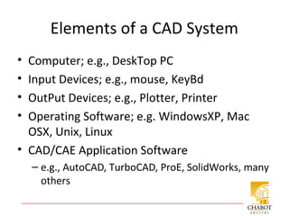
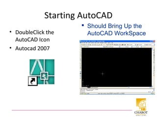
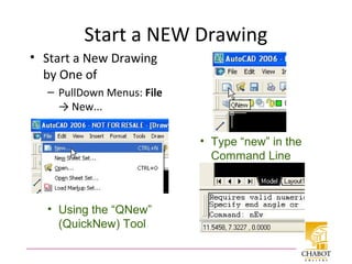
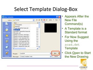
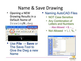
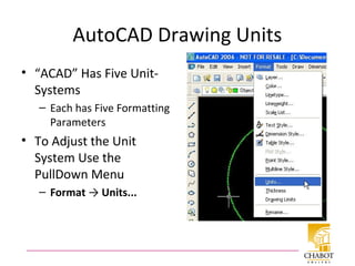
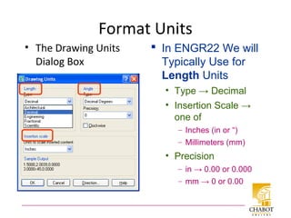
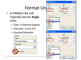
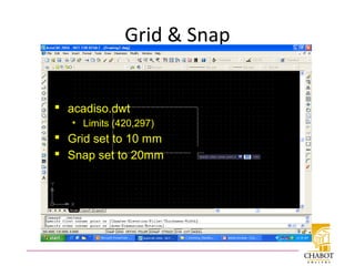
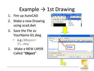
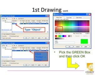
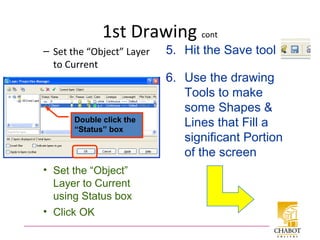
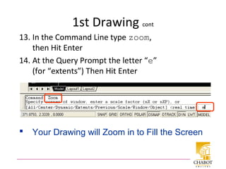
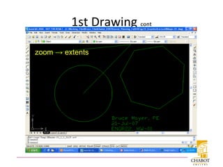
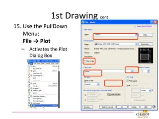
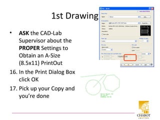
Presenting
Ahmed Hassan
Civil Engineer
Introduction toIntroduction to
AutoCADAutoCAD©©
What are the “C”, “A”, and “D”?
• CAD Stands for One of
– Computer Aided Design
• The More Typical Definition
– Computer Aided Drafting
• Sometimes See CADD or CAE
– Computer Aided Drafting & Design
• Covers Both Bases
– Computer Aided Engineering
• Typically CADD + Numerical-Analysis
Elements of a CAD System
• Computer; e.g., DeskTop PC
• Input Devices; e.g., mouse, KeyBd
• OutPut Devices; e.g., Plotter, Printer
• Operating Software; e.g. WindowsXP, Mac
OSX, Unix, Linux
• CAD/CAE Application Software
– e.g., AutoCAD, TurboCAD, ProE, SolidWorks, many
others
CAD Software
• Common Basic Elements
– Commands to generate geometry
• Makes Mathematically Accurate Lines, Curves,
Surfaces, Volumes, etc.
– Functions for controlling views
– Modifiers for changing drawing geometry
– Annotation commands for adding text,
dimensions, and notes
• The use of CAD has Revolutionized
Engineering Graphics
Starting AutoCAD
• DoubleClick the
AutoCAD Icon
• Autocad 2007
 Should Bring Up the
AutoCAD WorkSpace
AutoCAD WorkSpace
Status LineCoOrd Display
Command Line
Cursor
Object
Properties TB
Standard TB
PullDown Menus
Drawing TB
Layer TB
Modify TB
Drawing
Area
AutoCAD ToolBars: Move/Size
 ACAD ToolBars Can
Moved and Sized using
the Same Techniques as
with other MSWindows
Applications
ReSize CommandLine Box
Resize Using
Double-Bar Cursor
Recommend
Minimum 2-Lines
High
ToolBars Described
• AutoCAD ToolBars Behave in the Same Manner as
other Windows-Apps ToolBars
Each Icon is
called a “Tool”
Allowing the Cursor to
“Linger over a Tool
Brings up a Descriptive
“ToolTip”
Start a NEW Drawing
• Start a New Drawing
by One of
– PullDown Menus: File
→ New...
• Using the “QNew”
(QuickNew) Tool
• Type “new” in the
Command Line
Select Template Dialog-Box
• Appears After the
New File
Command(s)
• A Template is a
Standard format
• For Now Suggest
Using the
acad.dwt
Template
• Click Open to Start
the New Drawing
Name & Save Drawing
• Opening a NEW
Drawing Results in a
Default Name of
DrawingN.dwg
 Use File → Save or
The Save-Tool to
Give the Dwg a new
Name
 Naming AutoCAD Files
• NOT Case Sensitive
• Any Combination of
Letters and Numbers
– Also Allowed = $, -, _
• Not Allowed = , /, %, *
AutoCAD Drawing Units
• “ACAD” Has Five Unit-
Systems
– Each has Five Formatting
Parameters
• To Adjust the Unit
System Use the
PullDown Menu
– Format → Units...
Format Units
• The Drawing Units
Dialog Box
 In ENGR22 We will
Typically Use for
Length Units
• Type → Decimal
• Insertion Scale →
one of
– Inches (in or “)
– Millimeters (mm)
• Precision
– in → 0.00 or 0.000
– mm → 0 or 0.00
Format Units cont
• In ENGR22 We will
Typically Use for Angle
Units
– Type → Decimal Degree
– Precision → 0 or 0.0
– CounterClockwise
Standard Paper Sheet Sizes
• USA Standards (in)
– A = 8.5x11 (1.29 AR)
– B = 11x17 (1.55 AR)
– C = 17x22 (1.29 AR)
– D = 22x34 (1.55 AR)
– E = 34x44 (1.29 AR)
• Notes
– Nice, Round No.s
– Inconsistent Aspect
Ratios (ARs)
• ISO 216 Paper (mm)
– A4 = 210x297 (1.41 AR)
– A3 = 297x420 (1.41 AR)
– A2 = 420x594 (1.41 AR)
– A1 = 594x841 (1.41 AR)
– A0 = 841x1189 (1.41 AR)
• Notes
– UNround Numbers
– Constant Aspect Ratio = √2
Drawing Limits
• In ENGR22 HardCopy
Output will done on “A-
size” (8.5” x 11”) Paper
• ACAD Drawing Limits
set the Boundaries
– The “Limits” Usually Set
to Match the Paper Size
• Example: Set
Drawing Limits
1. Open a New Drawing
using acad.dwt
2. Use the PullDown
Menu: Format →
Drawing Limits...
Drawing Limits cont
• Brings up notation in
Command Line
3. Accept the Lower-
Left at <0.0000,
0.000> by hitting
Enter
– Brings the Next
Query into the
Command Line
4. Enter 11, 8.5 and
hit Enter to set the
Upper Right Limit
Grid & Snap
• Grid is just a visual aid
for your drawing
• Snap allows you to
specify precise
coordinates when
using the mouse
• They are modified
with the GRID and
SNAP commands
• Neither affect
anything already
drawn
• They can be changed
on-the-fly
• Function keys set GRID
and SNAP
• “modes”: on and off
• F7 - Sets GRID mode
on/off
• F9 - Sets SNAP mode
on/off
Grid & Snap
 acadiso.dwt
• Limits (420,297)
 Grid set to 10 mm
 Snap set to 20mm
Example → 1st Drawing
1. Fire up AutoCAD
2. Make a new Drawing
using acad.dwt
3. Save the File as
YourName-01.dwg
– e.g.; BMayer-
01.dwg
1. Make a NEW LAYER
Called “Object”
Click
1st Drawing cont
• Pick the GREEN Box
and then click OK
Type “Object”
Click
“Color →
white”
1st Drawing cont
– Set the “Object” Layer
to Current
Double click the
“Status” box
• Set the “Object”
Layer to Current
using Status box
• Click OK
6. Use the drawing
Tools to make
some Shapes &
Lines that Fill a
significant Portion
of the screen
5. Hit the Save tool
1st Drawing cont
Drawing
ToolBar
Save Again
1st Drawing cont
7. Use the Pull Down Menu: Draw
→ Text → Multiline Test...
8. Drag the mouse to
• form an “MTEXT” Box
• Activates the
“Text Formatting” Box
8. In the Format Box Change
the Text Size to 15-25
• Or Whatever fits your dwg
1st Drawing cont
MTEXT
Box
Change to 25
1st Drawing cont
10. Click in Inside the MTEXT Box
and Type Your HW-ID
– Fname Lname
– Date
– Class ID = ENGR22
– HW ID = HW-nn
11.Click OutSide the MTEXT
Box to DeActivate
12.Hit Save, yet again
1st Drawing cont
13. In the Command Line type zoom,
then Hit Enter
14. At the Query Prompt the letter “e”
(for “extents”) Then Hit Enter
 Your Drawing will Zoom in to Fill the Screen
1st Drawing cont
zoom → extents
1st Drawing cont
15. Use the PullDown
Menu:
File → Plot
– Activates the Plot
Dialog Box
1st Drawing cont
• ASK the CAD-Lab
Supervisor about the
PROPER Settings to
Obtain an A-Size
(8.5x11) PrintOut
16. In the Print Dialog Box
click OK
17. Pick up your Copy and
you’re done
All Done for Today
Thanks
for Listening

Auto cad introduction

  • 1.
    Presenting Ahmed Hassan Civil Engineer IntroductiontoIntroduction to AutoCADAutoCAD©©
  • 2.
    What are the“C”, “A”, and “D”? • CAD Stands for One of – Computer Aided Design • The More Typical Definition – Computer Aided Drafting • Sometimes See CADD or CAE – Computer Aided Drafting & Design • Covers Both Bases – Computer Aided Engineering • Typically CADD + Numerical-Analysis
  • 3.
    Elements of aCAD System • Computer; e.g., DeskTop PC • Input Devices; e.g., mouse, KeyBd • OutPut Devices; e.g., Plotter, Printer • Operating Software; e.g. WindowsXP, Mac OSX, Unix, Linux • CAD/CAE Application Software – e.g., AutoCAD, TurboCAD, ProE, SolidWorks, many others
  • 4.
    CAD Software • CommonBasic Elements – Commands to generate geometry • Makes Mathematically Accurate Lines, Curves, Surfaces, Volumes, etc. – Functions for controlling views – Modifiers for changing drawing geometry – Annotation commands for adding text, dimensions, and notes • The use of CAD has Revolutionized Engineering Graphics
  • 5.
    Starting AutoCAD • DoubleClickthe AutoCAD Icon • Autocad 2007  Should Bring Up the AutoCAD WorkSpace
  • 6.
    AutoCAD WorkSpace Status LineCoOrdDisplay Command Line Cursor Object Properties TB Standard TB PullDown Menus Drawing TB Layer TB Modify TB Drawing Area
  • 7.
    AutoCAD ToolBars: Move/Size ACAD ToolBars Can Moved and Sized using the Same Techniques as with other MSWindows Applications
  • 8.
    ReSize CommandLine Box ResizeUsing Double-Bar Cursor Recommend Minimum 2-Lines High
  • 9.
    ToolBars Described • AutoCADToolBars Behave in the Same Manner as other Windows-Apps ToolBars Each Icon is called a “Tool” Allowing the Cursor to “Linger over a Tool Brings up a Descriptive “ToolTip”
  • 10.
    Start a NEWDrawing • Start a New Drawing by One of – PullDown Menus: File → New... • Using the “QNew” (QuickNew) Tool • Type “new” in the Command Line
  • 11.
    Select Template Dialog-Box •Appears After the New File Command(s) • A Template is a Standard format • For Now Suggest Using the acad.dwt Template • Click Open to Start the New Drawing
  • 12.
    Name & SaveDrawing • Opening a NEW Drawing Results in a Default Name of DrawingN.dwg  Use File → Save or The Save-Tool to Give the Dwg a new Name  Naming AutoCAD Files • NOT Case Sensitive • Any Combination of Letters and Numbers – Also Allowed = $, -, _ • Not Allowed = , /, %, *
  • 13.
    AutoCAD Drawing Units •“ACAD” Has Five Unit- Systems – Each has Five Formatting Parameters • To Adjust the Unit System Use the PullDown Menu – Format → Units...
  • 14.
    Format Units • TheDrawing Units Dialog Box  In ENGR22 We will Typically Use for Length Units • Type → Decimal • Insertion Scale → one of – Inches (in or “) – Millimeters (mm) • Precision – in → 0.00 or 0.000 – mm → 0 or 0.00
  • 15.
    Format Units cont •In ENGR22 We will Typically Use for Angle Units – Type → Decimal Degree – Precision → 0 or 0.0 – CounterClockwise
  • 16.
    Standard Paper SheetSizes • USA Standards (in) – A = 8.5x11 (1.29 AR) – B = 11x17 (1.55 AR) – C = 17x22 (1.29 AR) – D = 22x34 (1.55 AR) – E = 34x44 (1.29 AR) • Notes – Nice, Round No.s – Inconsistent Aspect Ratios (ARs) • ISO 216 Paper (mm) – A4 = 210x297 (1.41 AR) – A3 = 297x420 (1.41 AR) – A2 = 420x594 (1.41 AR) – A1 = 594x841 (1.41 AR) – A0 = 841x1189 (1.41 AR) • Notes – UNround Numbers – Constant Aspect Ratio = √2
  • 17.
    Drawing Limits • InENGR22 HardCopy Output will done on “A- size” (8.5” x 11”) Paper • ACAD Drawing Limits set the Boundaries – The “Limits” Usually Set to Match the Paper Size • Example: Set Drawing Limits 1. Open a New Drawing using acad.dwt 2. Use the PullDown Menu: Format → Drawing Limits...
  • 18.
    Drawing Limits cont •Brings up notation in Command Line 3. Accept the Lower- Left at <0.0000, 0.000> by hitting Enter – Brings the Next Query into the Command Line 4. Enter 11, 8.5 and hit Enter to set the Upper Right Limit
  • 19.
    Grid & Snap •Grid is just a visual aid for your drawing • Snap allows you to specify precise coordinates when using the mouse • They are modified with the GRID and SNAP commands • Neither affect anything already drawn • They can be changed on-the-fly • Function keys set GRID and SNAP • “modes”: on and off • F7 - Sets GRID mode on/off • F9 - Sets SNAP mode on/off
  • 20.
    Grid & Snap acadiso.dwt • Limits (420,297)  Grid set to 10 mm  Snap set to 20mm
  • 21.
    Example → 1stDrawing 1. Fire up AutoCAD 2. Make a new Drawing using acad.dwt 3. Save the File as YourName-01.dwg – e.g.; BMayer- 01.dwg 1. Make a NEW LAYER Called “Object” Click
  • 22.
    1st Drawing cont •Pick the GREEN Box and then click OK Type “Object” Click “Color → white”
  • 23.
    1st Drawing cont –Set the “Object” Layer to Current Double click the “Status” box • Set the “Object” Layer to Current using Status box • Click OK 6. Use the drawing Tools to make some Shapes & Lines that Fill a significant Portion of the screen 5. Hit the Save tool
  • 24.
  • 25.
    1st Drawing cont 7.Use the Pull Down Menu: Draw → Text → Multiline Test... 8. Drag the mouse to • form an “MTEXT” Box • Activates the “Text Formatting” Box 8. In the Format Box Change the Text Size to 15-25 • Or Whatever fits your dwg
  • 26.
  • 27.
    1st Drawing cont 10.Click in Inside the MTEXT Box and Type Your HW-ID – Fname Lname – Date – Class ID = ENGR22 – HW ID = HW-nn 11.Click OutSide the MTEXT Box to DeActivate 12.Hit Save, yet again
  • 28.
    1st Drawing cont 13.In the Command Line type zoom, then Hit Enter 14. At the Query Prompt the letter “e” (for “extents”) Then Hit Enter  Your Drawing will Zoom in to Fill the Screen
  • 29.
  • 30.
    1st Drawing cont 15.Use the PullDown Menu: File → Plot – Activates the Plot Dialog Box
  • 31.
    1st Drawing cont •ASK the CAD-Lab Supervisor about the PROPER Settings to Obtain an A-Size (8.5x11) PrintOut 16. In the Print Dialog Box click OK 17. Pick up your Copy and you’re done
  • 32.
    All Done forToday Thanks for Listening

Editor's Notes

  • #3 Computer Aided (or Assisted) Design or Drafting. It means using computers to design products or architecture. Sometimes CAD output is sent directly to operate the machinery that makes the product; this is called Computer Aided Manufacturing. See CAM.
  • #33 Print tutorial