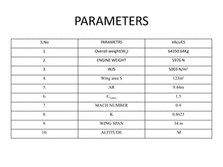
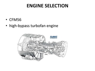
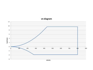
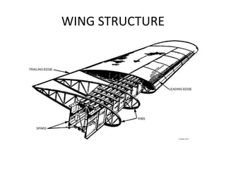
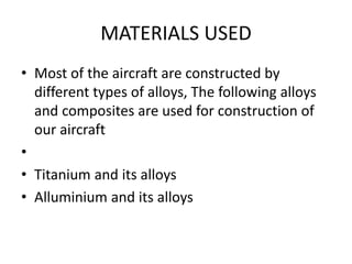
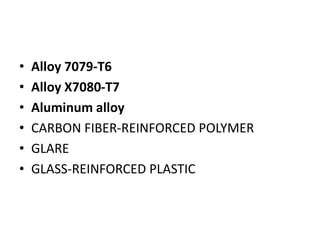
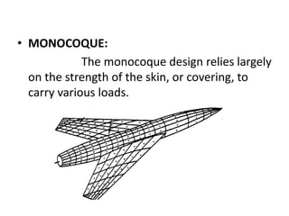
DESIGN OF 150 SEATER TRANSPORT AIRCRAFT
PARAMETERS
S.No PARAMETRS VALUES
1. Overall weight(Wo) 64350.64Kg
2. ENGINE WEIGHT 5976 N
3. W/S 5003 N/m2
4. Wing area S 123m2
5. AR 9.44m
6. CLmax 1.5
7. MACH NUMBER 0.9
8. K 0.8625
9. WING SPAN 34 m
10. ALTITUDE M
ENGINE SELECTION
• CFM56
• high-bypass turbofan engine
V-N DIAGRAM
The v-n Diagram limits the various external loads that
any airplane can withstand at any particular velocity. i.e. the graph
plotted between the load factor versus velocity is known as v-n
diagram. Generally the airplane experiences much higher loads
than the design values. Hence a safety factor is used in the
structural design.
-6
-4
-2
0
2
4
6
8
10
12
0 100 200 300 400 500 600 700 800 900
loadfactor
velocity
vn diagram
GUST LOAD
• Gust loads are unsteady aerodynamic loads
that are produced by aerodynamic turbulence.
The effect of turbulent gust is to produce a
short time change in the effective angle of
attack. This change can either be positive or
negative, thereby producing an increase or
decrease in the wing lift and change in the
load factor.
WING DESIGN
• The single cell construction, which is otherwise called
the monocoque wing construction, is generally not preferred as
since the skin is required to take all structural loads, the skin
thickness required is very great, which increases the weight greatly.
• The 2 cell construction making use of a single main spar
is generally weak since the rear portion of the wing, which contains
control surfaces, is unsupported. The rearward COP case becomes
highly critical in this kind of construction.
• The multiple cell construction involving more than 2
spars also is disadvantageous in terms of weight, since higher
number of spars unnecessarily increases the weight.
WING STRUCTURE
MATERIALS USED
• Most of the aircraft are constructed by
different types of alloys, The following alloys
and composites are used for construction of
our aircraft
•
• Titanium and its alloys
• Alluminium and its alloys
• Alloy 7079-T6
• Alloy X7080-T7
• Aluminum alloy
• CARBON FIBER-REINFORCED POLYMER
• GLARE
• GLASS-REINFORCED PLASTIC
FUSELAGE DESIGN
• Monocoque
• Semimonocoque
• Reinforced shell.
• MONOCOQUE:
The monocoque design relies largely
on the strength of the skin, or covering, to
carry various loads.
• Semimonocoque design overcomes the
strength-to-weight problem of monocoque
construction.
• The semimonocoque construction has the skin
reinforced by longitudinal members
DESIGN OF FUSELAGE COMPONENTS
• In aircraft construction, a longeron or stringer
or stiffener is a thin strip of wood, metal or
carbon fiber, to which the skin of the aircraft is
fastened. Longerons are attached to formers
(also called frames),
3-D DIAGRAM
DESIGN OF MISCELLANEOUS MEMBERS
• WING FUEL TANKS
• HORIZONTAL STABILISER
• VERTICAL STABILISER
• HINGED CONTROL SURFACES
• PIVOTED CONTROL SURFACES
• ATTACHMENT OF LIFTING SURFACES:
CONCLUSION
• ‘Design’ is a fine blend of science, creativity, presence of mind and the
application of each one of them at the appropriate time. Design of
anything needs expertise and an optimistic progress towards the ideal
system. The scientific society always looks for the best product design.
This involves strong fundamentals in science and mathematics and their
skillful applications, which is a tough job endowed upon the designer.
• We have put up enough hard work to the best of our knowledge for
this design project. A design never gets complemented in a fuller sense
but it is one further step towards the ideal system. But during the design
of this aircraft, we learnt a lot about aeronautics and its implications when
applied to an aircraft design.

Ppt

  • 1.
    DESIGN OF 150SEATER TRANSPORT AIRCRAFT
  • 2.
    PARAMETERS S.No PARAMETRS VALUES 1.Overall weight(Wo) 64350.64Kg 2. ENGINE WEIGHT 5976 N 3. W/S 5003 N/m2 4. Wing area S 123m2 5. AR 9.44m 6. CLmax 1.5 7. MACH NUMBER 0.9 8. K 0.8625 9. WING SPAN 34 m 10. ALTITUDE M
  • 3.
    ENGINE SELECTION • CFM56 •high-bypass turbofan engine
  • 4.
    V-N DIAGRAM The v-nDiagram limits the various external loads that any airplane can withstand at any particular velocity. i.e. the graph plotted between the load factor versus velocity is known as v-n diagram. Generally the airplane experiences much higher loads than the design values. Hence a safety factor is used in the structural design.
  • 5.
    -6 -4 -2 0 2 4 6 8 10 12 0 100 200300 400 500 600 700 800 900 loadfactor velocity vn diagram
  • 6.
    GUST LOAD • Gustloads are unsteady aerodynamic loads that are produced by aerodynamic turbulence. The effect of turbulent gust is to produce a short time change in the effective angle of attack. This change can either be positive or negative, thereby producing an increase or decrease in the wing lift and change in the load factor.
  • 7.
    WING DESIGN • Thesingle cell construction, which is otherwise called the monocoque wing construction, is generally not preferred as since the skin is required to take all structural loads, the skin thickness required is very great, which increases the weight greatly. • The 2 cell construction making use of a single main spar is generally weak since the rear portion of the wing, which contains control surfaces, is unsupported. The rearward COP case becomes highly critical in this kind of construction. • The multiple cell construction involving more than 2 spars also is disadvantageous in terms of weight, since higher number of spars unnecessarily increases the weight.
  • 8.
  • 9.
    MATERIALS USED • Mostof the aircraft are constructed by different types of alloys, The following alloys and composites are used for construction of our aircraft • • Titanium and its alloys • Alluminium and its alloys
  • 10.
    • Alloy 7079-T6 •Alloy X7080-T7 • Aluminum alloy • CARBON FIBER-REINFORCED POLYMER • GLARE • GLASS-REINFORCED PLASTIC
  • 11.
    FUSELAGE DESIGN • Monocoque •Semimonocoque • Reinforced shell.
  • 12.
    • MONOCOQUE: The monocoquedesign relies largely on the strength of the skin, or covering, to carry various loads.
  • 13.
    • Semimonocoque designovercomes the strength-to-weight problem of monocoque construction. • The semimonocoque construction has the skin reinforced by longitudinal members
  • 14.
    DESIGN OF FUSELAGECOMPONENTS • In aircraft construction, a longeron or stringer or stiffener is a thin strip of wood, metal or carbon fiber, to which the skin of the aircraft is fastened. Longerons are attached to formers (also called frames),
  • 15.
  • 16.
    DESIGN OF MISCELLANEOUSMEMBERS • WING FUEL TANKS • HORIZONTAL STABILISER • VERTICAL STABILISER • HINGED CONTROL SURFACES • PIVOTED CONTROL SURFACES • ATTACHMENT OF LIFTING SURFACES:
  • 17.
    CONCLUSION • ‘Design’ isa fine blend of science, creativity, presence of mind and the application of each one of them at the appropriate time. Design of anything needs expertise and an optimistic progress towards the ideal system. The scientific society always looks for the best product design. This involves strong fundamentals in science and mathematics and their skillful applications, which is a tough job endowed upon the designer. • We have put up enough hard work to the best of our knowledge for this design project. A design never gets complemented in a fuller sense but it is one further step towards the ideal system. But during the design of this aircraft, we learnt a lot about aeronautics and its implications when applied to an aircraft design.