11. HYDRAULIC SYSTEM
The B737-800 aircraft has three hydraulic power systems: A
system, B system, and the Standby system. The three
systems operate the same as those on the B737-300/400
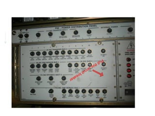
aircraft, but with some exceptions. The power supplies to the
electrical hydraulic pumps cross over and the Circuit
Breakers (C/B) are located on the Electrical Power
Distribution Panels in the E&E Bay.
The A system pump control C/B is on the #2 Distribution
Panel on the right side of the E&E rack, whilst the B system
pump control C/B is on the #1 Distribution Panel on the left
side of the E&E rack. There is also a 3 phase heavy duty
C/B for each system located inside the distribution panel.
in
pu sid CAUTION: The control C/B’s MUST be PULLED and
St mp e th TAGGED to disable the main hydraulic pumps.
a n c is
db irc pa
y uit ne The standby hydraulic system pump is located inside the R/H
hy b l aft wing to body fairing along with the brake accumulator.
The Standby Hydraulic Pump is isolated by tripping and
dr re
au ak
lic er tagging the circuit breaker located inside the #2 power
distribution panel. There is no control breaker on the outside
of the panel for the standby system.
Always ensure that the tag is on a long string and hangs
outside the panel when the front cover is closed.
WARNING: This breaker must NOT be tripped or reset when
power is on the aircraft as there are lethal voltages at
exposed terminals within the distribution panel.