(ANVI) Koregaon Park Call Girls Just Call 7001035870 [ Cash on Delivery ] Pun...
US 3904525
1. United States Patent (19) (11 3,904,525
Rosenberg (45) Sept. 9, 1975
(54) WASTE TREATMENT APPARATUS 57 ABSTRACT
76) Inventor: Lawrence R. Rosenberg, 1 Chelsea This patent discloses waste treatment apparatus in
Ridge Dr., Wappingers Falls, N.Y. which after primary treatment of waste (liquid waste)
12590 aeration of the waste occurs in the equalization tank
(22 Filed: Aug. 23, 1973 to start the process to change the normally anerobic
21 ) Appl. No.: 390,892
52) U.S. Cl.................................... 210/150; 261/92
5 i Int. Cl........................................... B01D 33/28
(58) Field of Search....... 210/15, 17, 150, 151, 170,
210/195, 218-221; 261/92, DIG. 75
56) References Cited
UNITED STATES PATENTS
2,591,497 4f1952 Berl................................ 210/150 X
3,269,542 8/1966. Renzi et al...... ... 21Of 17 X
3,371,033 2/1968 Simmons et al. ... ..., 21Of 17 X
3,528,549 9/1970 Ray..................... ... 210/151
3,618,778 11/1971 Benton et al....... ... 2)Of150
3,660,277 5f1972 McWhirter et al. ... 210/15 X
3,680,704 8, 1972 Schaefer ............. ... 2. Of17O X
3,681,236 8/1972 Bergles ct al... ... 20/195 X
3,777,891 12/1973 Stengclin ............................ 210/150
3,788,478 1/1974 Savage ......... ... 210/221 X
3,789,986 2/1974 Oldham et al.. ... 210/151 X
3,827,559 8/1974 Gass ct al. .......................... 210/150
Primary Examiner-Samih N. Zaharna
Assistant Examiner-Robert H. Spitzer
Attorney, Agent, or Firm-William J. Dick
waste material to at least a partially aerobic state.
Thereafter the waste material is applied by a spray to
at least the first stages of a rotating disk biological re
actor where biological slimes are grown on the rotat
ing disks, which slimes serve to further the process of
removing pollutants from the waste being supplied
thereto. The reactor section is comprised ofa plurality
ofdisks each made up ofgroups ofthin wedge shaped
elements of at least a pair of sets, each element of a
set cooperating with each other element in tightly
packed relation for ease ofshipping while when mated
with the elements of the other set are spaced apart,
and when connected together about the rotating shaft
ofthe reactor form spaced apart disks upon which the
biological slime may form.
The purpose of this abstract is to enable the public
and the Patent Office to determine rapidly the subject
matter of the technical disclosure of the application.
This abstract is neither intended to define the
invention of the application nor is it intended to be
limiting as to the scope thereof.
Claims, 16 Drawing Figures
2. 3,904,525PATENTEDSEP 91975
SEET 1. Of 8
5
zzzzzz
2
ZZZazaaZZzaaZZZZZZ
FG.
4.
NSSSS3sZZZZZZZZZZZ
(~~~<<<<<<<<<=1)<<<<<<=<--<--<--<avaZZZZZZZZZZZZZZZZZZZZZZZZ
II
NYSOESOENS,N,N,No..
10. 3,904,525
WWASTE TREATMENT APPARATUS
SUVMARY, OF THE INVENTION AND STATE OF
THE PRIOR ART
The present invention relates to apparatus for waste
treatment, and more particularly relates to improve
ments in biological reactors, pre-effluent aeration and
supply of effluent to the reactor.
Because ofthe increased concern by thegeneral pop
ulation and thus of Government regulatory agencies,
water purification has become one ofthe primary con
cerns of the ecologists. Obviously population shifts as
well as industrial expansion has created a problem by
a constant increase in the level of pollution of lakes,
rivers and streams. To reverse the trend of increased
pollution ofsuch bodies of water it has become neces
sary to increase the size and efficiency ofexistingwaste
treatment facilities while improving on new plants with
out an overt increase in the cost of construction of new
plants.
By way ofbackground there are three basic processes
presently in use for waste treatment. The most widely
recognized of the three processes is that of primary
waste treatment in which sedimentation occurs to ef
fect the removal ofthe solids which may settle from the
waste water. Ofcourse, chemical coagulants are some
times used to increase the efficiency of the process in
which case the primary treatment may remove up to
50% of the carbonaceous pollutants when such pollut
ants may be expressed by bio-chemical oxygen demand
(hereinafter referred to as B.O.D.)
The second process utilized for the treatment of
waste water in normally termed a secondary treatment
process which is accomplished conventionally by pro
vidingapparatus which permits the growth ofbiological
slimes (sometimes called biomasses) orflocs which ulti
lize the pollutants in the waste media to enhance their
natural growth processes. In the secondary treatment
process, the waste water is brought into contact with
the biological slimes to supply nutrients and oxygen to
the micro organisms, the slimes then being separated
from the waste water to effect the necessary purifica
tion or clarification of the waste media. Thus in this
type of secondary treatment process, it is necessary
that the biological slime be provided with a continuous
supply of nutrients so as to maintain the growth ofthe
micro organisms as well as requiring a continued oxy
gen supply to effect the nutrition process.
The second process of secondary treatment of waste
water which has gained wide acceptance is known as
the activated sludge process which providesforthe aer
ation ofthe waste water in the presence ofa controlled
amount offree floating biological flocs. The microor
ganisms in the biological flocs extract the pollutants
from the waste water, thereby deriving their nutrition,
and are supplied with oxygen by diffused air which is
injected below the surface of the aeration tank. Thus
pollutants may be removed from the waste material by
conversion into biological slimes which feed, in a con
tinuous cycle, upon the nutrients of the waste along
with appropriate oxygenation. While this process can
remove approximately 60% of the carbonaceous
B.O.D., employing certain variations in aeration, such
as modified aeration and step aeration, up to 90% of
the carbonaceous B.O.D. as well as oxidation ofammo
nia nitrogen may occur.
10
15
25
35
40
45
50
55
2
The third basic process for treating waste water is
commonly referred to as the standard rate or high rate
trickling filtration process. In this type of process, set
tled waste media is passed over biological slimes grown
on and attached to stationary surfaces. Purification or
clarification of the waste media occurs in a manner
similar to the activated sludge process in that organic
pollutants in the waste water are converted into biolog
ical slimes that are subsequently separated from the
clarified media. Plants employing such a process nor
mally effect a removal of between 60 and 90% of the
carbonaceous B.O.D. depending upon the flow rate
and the load presented to the filtration media.
In recent years a fourth process has come into vogue,
this process being generally referred to as a rotating
disk process for secondary biological waste media
treatment. The process evolved from basic work and
research that was conducted in Germany in the mid
50's. Due to its inherent advantages, which will be dis
cussed more fully hereinafter, there are numerous such
installations existing today in western Europe. In the
mid 60's the process was introduced into the United
States. In this secondary biological waste water treat
ment process, large diameter plastic media or disks are
mounted on a horizontally disposed shaft and rotated
slowly in a tank with 40 to 50% of the surface area of
the disks being submerged in the waste media at any
one time. Organisms which are present in the waste
water adhere to the rotating disks and multiply, form
ing a biological mass on the surface of the rotating
disks. As the disks rotate, the water in the tank moves
down the disk, absorbing oxygen from the surrounding
air. The organisms not only remove oxygen from the air
butalso remove both dissolved oxygen and organic ma
terials from the film of water as it moves down the ro
tating disk. The normal stress of the biological mass
and the shearing forces due to the weight of the mass
as it passes through the waste media causes any excess
biological mass to drop from the disk into the waste
media. In this manner clogging of the disks is pre
vented, while a constant biological mass of micro or
ganisms is kept in the media. Additionally, the rotating
disks create a mixing action which maintains the solids
in suspension until the treated waste water carries the
waste, including the solids, out of the tank for separa
tion and disposal. The advantages of the rotating bio
logical disks are many: (1) the surface area ofthe disks
is far greater than the surface area ofthe waste media
in the tank, permitting the development ofa large area
of fixed biological culture; (2) the movement of the
disks through the media provides vigorous contact of
the biological mass with the waste media providing eff
cient aeration of the waste media; (3) the rotation of
the reactor provides for agitation of the media.
However, there are some disadvantages to the exist
ing apparatus utilized for rotating biological reactors.
For example, in large plants where the disks are of
great diameter there is difficulty in shipping the disks
O from their point of manufacture to the point of assem
65
bly, requiringspecial packing,special carriers resulting
in increased costs of plant construction. Additionally,
due to the very large diameter of the disks anywhere
from 12 to 24 feet in diameter and even more, molds
forformation ofthe disks are extremely expensive rais
ing the cost ofmanufacture. Also, because of the way
Some systems are presently employed, the waste water
iscomposedalmostentirely ofananaerobicpopulation
11. 3.
which requires excessively large biological reactors to
effectively provide secondary treatment to the waste
media.
In view of the above, it is a principal object of the
present invention to provide an improved rotating bio
logical reactor which is easier to assemble in the field.
Another object ofthe present invention is to provide
an improved biological reactor disk in which the disk
is composed ofa plurality ofindividual elements to fa
cilitate construction in the field as well as ease ofship
ping. -
Yet another object of the present invention is to pro
vide an improved disk for a biological reactor in which
the individual disks are formed of a plurality of ele
ments, each element of adjacent disks being adapted
for cooperation with the elements of disks on opposite
sides thereof so as to permit ease of alignment of the
disks and proper spacing thereof from disk to disk.
Yet another object ofthe present invention is to pro
vide elements of a disk ofa rotating biological reactor
in which the elements of some of the disks may be
packed in nested relation one with regard to the other
for ease of shipment, and which may be more easily
handled in the field when mating with elements of an
other set.
Still another object ofthe present invention is to pro
vide means for at least starting the aerobic process by
supplying oxygen to the media in the equalization tank
so as to reduce the loading effect on the first stages of
the biological reactor.
Yet another object ofthe presentinvention is to pro
vide the novel manner of moving the media onto the
initial stages of the biological reactor so as to increase
the effective area ofthe initial stages ofthe reactor, and
to prevent inadvertent biomass removal from the initial
stages during periods of high media throughput.
Other objects and a more complete understanding of
the invention may be had by referring to the following
specification and claims taken in conjunction with the
accompanying drawings in which: -
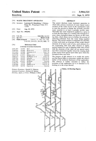
FIG. is a fragmentary sectional view ofprimary and
secondary treatment apparatus constructed in accor
dance with the present invention;
FIG. 2 is an enlarged fragmentary sectional view
taken along line 2-2 of FIG. ;
FIG. 3 is an enlarged fragmentary sectional view
taken along line 3-3 of FIG. 1;
FIG. 3A isan enlarged fragmentary view ofa portion
of the apparatus illustrated in FIG. 3;
FIG. 4 is a fragmentary sectional side elevational
view of a portion of the apparatus illustrated in FIGS.
1-3;
FIG. 5 is a fragmentary sectional view taken along
line 5-5 of FIG. 4;
FIG. 6 is a perspective view ofa plurality ofelements
comprising a group adapted for coupling to the appara
tus best illustrated in FIGS. 3 and 4:
FIG. 6A is an enlarged fragmentary perspective view
taken along line 6A-6A of FIG. 6;
FIG. 6B is an enlarged fragmentary sectional view
taken along line 6B-6B of FIG. 6;
FIG. 7 is an enlarged fragmentary sectional view
through a plurality of the elements illustrated in FIG.
6 to show their relationship one to the other;
FIG. 8 is a fragmentary sectional view illustrating
some of the elements illustrated in FIG. 6 positioned
for shipmentfrom a manufacturingsource to ajob site;
3,904,525
... O
5
25
30
35
40
45
50
55
60
65
4.
FIG. 9 isa fragmentary sectional view, similar to FIG.
7 but showing another embodiment of elements con
structed in accordance with the present invention;
FIG. 10 is a fragmentary sectional view, similar to
FIG.8 but showing some of the elements illustrated in
FIG. 9 in nested relation for shipment from a manufac
turing source; -
FIG. 1 is a fragmentary plan view of another em
bodiment showing alternate means to hold groups of
elements in the apparatus illustrated in FIGS. 1-4;
FIG. 12 is an enlarged fragmentary view ofa portion
of the apparatus illustrated in FIG. 11; and
FIG. 13 is a fragmentary sectional view taken along
line 13-13 of FIG. 12.
Referring now to the drawing, and especially FIG. 1
thereof, a primary and partial view of a secondary
treatment apparatus 10 and 50 respectively is illus
trated therein. In the illustrated instance the primary
treatment apparatus comprises the well known septic
tank, which includes a first compartment 11 which is .
joined to a second compartment 12, the compartments
being divided by an upstanding wall 3 having a port
13A therein at the approximate midpoint of the wall.
The first compartment 11 includes a waste or raw sew
age inletpipe 14which supplies raw sewage to the first
compartment 11 ofthe septic tank. As is conventional,
the septic tank acts as a settling tank, the sludge or
heavier material 15 falling to the bottom ofthe tank or
first compartment 11, while the lighter grease or scum
moves up the liquid waste and floats along the upper
surface thereof as at 16. At the central portion of the
first compartment the waste waterisclearerthan either
the upperor lowerportion,and thusthe clarified waste
water moves through port 3A into the second com
partment 12 wherein additional clarification occurs,
sludge 15 also settling into the bottom in compartment
12 while scum and grease float on the surface of the
upper portion. In the second compartment, once again
therefore, the central portion ofthe waste media forms
a clarified zone. Accordingly, the flow of waste media
is normally taken from this clarified zone and moved
therefrom into further processing apparatus.
Asshown in FIG. 1,an outlet pipe 17 extends into the
clarified zone and hasan outlet port 18 which projects
through an upstanding wall 19 separating the second
compartment from an equalization, sometimes called
an antisurge tank 20. The equalization or antisurge
tank 20functionsto equalize the dailyflow and thereby
even outtheflow to the secondary treatmentapparatus
S. . . .
Conventionally the waste material entering from the
Septic tank or primary treatment apparatus into the
equalization tank 20isanaerobic with regard toits con
tent of oxygen. (Anaerobic means “devoid of oxy
gen'.) Thus the waste matter thatis in the equalization
tank is anaerobic and at the same time full of organic
matter because the bacteria has consumed all of the
available oxygen. Conventionally, the anaerobic waste
material isthen applied to a secondary treatmentappa
ratus wherein oxygen is supplied to allow bacteria
growth to consume the organic matter in the waste me
dia, thereby removing the waste material.
In accordance with a feature ofthe invention, means
are provided in the equalization tank to start the pro
cess ofchangingthe normallyanaerobic waste material
to at least make the waste media partially aerobic. To
this end, and as best illustrated in FIGS. 1 and 2, the
12. 3,904,525
S
equalization tank 20 isprovided with at leastone, in the
illustrated instance a pair of dosing pumps 21, the
pumps beingdesignated 21A and 2 B (FIG. 2) for pur
poses of identification, which feed the waste media in
the equalization tank through discharge piping 22,
(22A and 22B) to the secondary treatment apparatus
50. Each of the discharge piping includes a metering
valve 23, (23A and 23B) to meter the flow from the
equalization tank to the secondary treatment appara
tuS.
In accordance with this feature of the invention,
means are provided to supply oxygen to the waste
media in the equalization tank. To this end, on the inlet
side of the metering valves 23A, 23B is a recirculating
or feedback line or pipe 24 which supplies a recirculat
ing stream of waste media to an aerator, in the illus
trated instance a venturi type nozzle discharge pump
25, and designated 25A and 25B in FIG. 2. The aerator
or venturi pump 25 has an air inlet pipe 26 which ex
tends vertically in the equalization tank and is con
nected to the atmosphere or a source ofairso as to per
mit, as the pump 25 operates, the drawing into and dis
charge from the pump of oxygen containing air. Al
though not shown, the air inlet piping of each venturi
pump (25A, 25B) may be joined to the air inlet piping
of the other to form a common air intake or the intakes
may be separate.
Inasmuch as the oxygen supplied by the aerating or
venturi pump 25 to the waste media in the equalization
tank tends to move upwardly through the waste, the
discharge being preferably near or adjacent the bottom
of the equalization tank, an air space or pocket will
form at the upper portion ofthe tank which may, ifde
sired, by recycled through the aerator and the tank by
providing a vent 27 at the top of the tank, which vent
is connected to an ozone generator 28, such as the
ozone generator sold by C. E. Bauer Company of
Springfield, Ohio. In this embodiment, the apparatus
28 may also have an intake 26A from the atmosphere
through it so that a constant charge of fresh air is sup
plied to the aerating or venturi pump 25.
Thus even with the metering valves 23 closed down,
a constantdischarge ofwaste media through the piping
or recirculating line 24 occurs and thus the pump 25
effects preliminary aeration of the waste media in the
equalization tank starting the process of injecting dis
solved oxygen into the waste media and permitting the
initial formation of some oxygen requiring bacteria to
commence the process of removing nutrients (organic
material) from the waste media. Additionally, even this
preliminary head start on formation of or changing of
the waste media in the equalization tank to at least a
partiallyaerobic nature willgive a headstartto the sec
ondary treatment apparatus permitting an overall re
duction in the size of the secondary treatment appara
tus for given flow conditions.
Under normal operating conditions only one of the
dosing pumps 21 is conventionally used to discharge
waste media from the equalization tank 20 into the sec
ondary treatmentapparatus50. However, itis normally
required that there be a standby dosing pump so that
in the event ofbreakdown ofone ofthe pumps, the sys
tem will not have to be shut down when one pump is
out of operation and being repaired. Accordingly, and
as bestshown in FIG.2, the metering valves23 are con
ventionally connected through piping 30A and 30B to
a tee 31 which discharges the waste media through line
O
15
25
30
35
40
45
50
55
60
65
6
32 to the inlet ofthe secondary treatment apparatus 50.
In conventional plants the piping 32 discharges di
rectly into the first compartment of the secondary
treatment apparatus 50 which under normal loading
conditions issatisfactory. However, and as will be more
fully explained hereinafter, under conditions of severe
loading, that is when waste media flow is at a very high
rate, thatis the metering valves 23 are wide open, many
times the hydraulic agitation effects a removal of the
biological slime (biomass) from the initial stages ofthe
rotating biological reactor. This cuts down the effi
ciency of the secondary treatment apparatus and can
result in degradation of the entire system because of
the removal of the nutrient consuming bacteria from
the initial stages ofthe reactor. Accordingly, and in ac
cordance with one feature of the invention, extending
the inlet piping32 in opposite directions along the inlet
ofthe tank 51 ofthe biological reactor and by provid
ing a plurality of apertures 33 in the piping 34A and
34Bthus extended the media may be sprayed out ofthe
piping along the entire width of the tank 51 inhibiting
severe hydraulic agitation, even under high flow condi
tions. Preferably the apertures 33A are directed down
wardly so that the media entry is into the tank as op
posed to being against the first stages ofthe reactor. In
this connection the apertured single pipe could be a
plurality of inlet pipes.
Because of the increased flow which is possible due
to pre-aeration, and in the event that it is desirable to
operate both dosing pumps 21A and 2 B, the systems
may be split such as shown in dotted lines in FIG. 2 so
that the inlet piping from pump 21A may extend di
rectly as through piping or inlet line 32A into a sepa
rate entry pipe 34A, while the inlet to the tank 51 from
dosing pump 21 B may be in a like manner split as at
32B and enter into a separate inlet line as at 34B. Ifde
sired, the pipes 34A and 34B may be joined at the cen
tral portion of the tank as by a valve (not shown) so
that the systems may be segregated orjoined together.
The placement of a valve intermediate the two lines
will permit the use ofjust one pump as desired and will
permit segregation of the systems in the event that re
pair or cleaning is necessary in either of the systems.
The secondary treatment apparatus ofthe illustrated
system comprises a biological reactor (as it has come
to be known in the trade) which includes a compart
mented tank 51 havinga contoured bottom with longi
tudinally spaced apart baffles or weirs (not shown) to
separate the tank into longitudinally extending com
partments. As shown in FIGS. 1-4, the reactor com
prises a rotor 55 mounted for rotation in the tank 51,
and includes at least first and second sets 60A and 60B
of radially projecting arms 61 which are spaced about
the rotor 55 and coupled thereto, the first set of arms
60A being axially spaced (see FIG. 4) from the second
set of arms 60B. In accordance with the invention, a
plurality of groups 70 of spaced apart pie or wedge
shaped elements are arranged in superimposed, juxta
position relation. Eachgroup 70 elements is positioned
intermediate adjacent radially projecting arms 61 of
each of the first and second sets 60A and 60B, the
groups forming thereby a plurality ofdisks 71 extend
ing along the rotor 55. Coupling means 72 releasably
couple each group ofelements 70 to the arms 61. Drive
means 52, in the illustrated instance an electric motor
(see FIG. ), effect a slow rotation ofthe rotor so as to
cause atleasta partial sumbersion ofthe groups ofele
13. 3,904,525
7
ments into the waste media in the tank during each ro
tation of the rotor.
in accordance with the invention the groups interme
diate the longitudinally separated radially extending
arms 6 of the set of arms 60A and 60B comprise Sets
of thin, wedge or pie shaped elements 73 and 74, the
elements 73 forming a first set, and the elements 74
forming a second set. Each of the elements ofa set has
opposite major surfaces 73A, 73B, 74A, 74B and ar
ranged so that elements of the first set are interdigi
tated with respect to the elements of the second set to
thus form a group.70. As will be more fully explained
hereinafter, the elements of each set are designed for
mating in nested relationship with other elements of its
own set, and adapted for a coacting spaced apart rela
tionship and alignmentwith elements ofthesecond set.
Each of the elements of each of the sets of elements
includes a plurality of protrusions 75 and depressions
76 therein, the protrusions and recessions, in the illus
trated instance, being substantially identical in the
plane ofthe major surfaces, although in FIG.6 to avoid
an optical illusion, the depressions76 are shown merely
as rectangles while the protrusions 75 are shown in de
tail. As shown in FIG. 6A, each ofthe protrusions and
depressions is preferably in the form of truncated
pyramids, which, due to the thinness of the material
used (such as polypropalene, polyethelene, etc.) serves
to stiffen the wedge shaped element.As illustrated best
in FIG.6, each ofthe protrusions and depressions is ad
jacent one another in a preset predetermined pattern,
which aids in the stability of the segment or element
and adds to increase the effective surface area thereof.
Circumscribing each ofthe elements in a broken array
is an upstanding rib 77 which projects from one major
surface of the elements, the rib serving, in a like man
ner, to stiffen the element in conjunction with a central
rib or the like 78. Further stiffening action is obtained
by the short ribs 79 which project from the rib 77, at
various portions therealong. For purposes which will
become more clear hereinafter, the protrusions 75 of
the elements 73 of the first set are arranged to mate
with like protrusions in the elements 74 of the second
Set.
In order to maintain the elements of one set in inter
digitated spaced apart relation with respect to the ele
ments of the other set, integral spacer and alignment
means are preferably formed in the elements 73 and
74. To this end, and referring now to FIGS. 6, 6A, 6B
and 7, each of the elements 73 and 74 includes integral
spacers which cooperate with receptacles in the adja
cent elements. In the illustrated instance, alternate
ones of the protrusions 75 have a cone shaped projec
tion 75A, while intermediate protrusions have a recep
tacle or dimple 75B. The projections 75A and recepta
cles 75B of the elements 73 being offset from the pro
jections and receptacles of the elements 74. Addition
ally the ribs 77 and central rib 78 include spacers or
projections 80 which alternate with receptacles or dim
ples 81, the spacers and receptacles of one set of ele
ments 73 being offset with respect to like parts on the
elements 74. The projections or spacers 75A and 80
may take any suitable form, in the present instance sub
stantially conical, the tip abutting in the flat bottom of
the receptacle in the adjacent element. The spacers
serve to position the adjacent elements of the opposite
set a predetermined distance apart to permit the
growth ofbiological mass therebetween while effecting
O
15
25
35
40
45
SO
55
65
8
maximum surface contact of each ofthe elements with
the waste media, permitting the waste water or media
to drain from the elements as they are raised out ofthe
tank by rotation and effecting maximum exposure of
the biological slime to air.
Additionally, and as illustrated in FIG. 7, it may be
desirable to provide integral alignment means so that
the elements which are interdigitated may lock one to
the other to effect not only rigidity ofthe group, but to
prevent inadvertent displacement of one element with
respect to the other. To this end, the alignment means
82 comprises a pocket 83 which frictionally engages a
latch.84 in the adjacent element. Each of the elements
includes both pockets and latches, the pockets in one
element ofaset adapted for coacting frictional engage
ment with latches of the adjacent element, when one
element of a set is mated with an element of another
set.As best illustrated in FIG. 6, the pockets 83 are re
inforced by radially extending ribs 87 which aid in giv
ing to the pockets a spring like action when the latch
84 enters into the pocket.
itshouldbe recognized that in certain constructions,
it may be desirable to make a unitized construction of
the elements forming a group. To fabricate such a con
struction it is a simple matter to effect a preselected
points localized heating of adjacent elements.For ex
ample, the latches 84 may be spot welded, the bottom
83A ofthe pocket, the weld being easily affected in as
sembling the elements by an application of heat to the
pocket and tip of the latch 84 as the elements are as
sembled forming thereby an intergral structure of the
group. Of course the elements may take many forms,
which lend themselves to localized spot welding of one
element to the other by spot heating. For example, and
as shown in FIG. 9, elements 173 and 174 having pro
trusions 175 and depressions 176 may include integral
alignment means 82 which comprise stepped pockets
183 which cooperate in frictional engagement with like
formed latches 84. In theillustrated instance, to facili
tate such welding process, the latch 184 includes a flat
184A at the upper portion thereoffor intimate contact
with the interior surface 183A of the pocket. The flat
surface to flat surface contact facilitates the welding of
the two surfaces one to the other merely by heating, for
example with a hot iron, the outside of the pocket.
Each of the elements of a set is adapted for nesting
with elements of its own set to make a compact pack
age for shipment purposes from, for example, a manu
facturing source.Such a stack of elements is illustrated
in FIGS. 8 and 10 wherein the elements may be either
of the sets 73, 74 or as shown in FIG.10, the elements
173 or 174. In either case, these drawings illustrate the
compact and nested arrangement of the elements one
with respect to the other which facilitates their package
ing for shipment.
After the elements have been shipped to some loca
tion, either the job site or the fabrication place, they
are assembled into the form best illustrated in FIGS. 6
and 7. After assembly the elements 73 being interdigi
tated with the elements 74, to form a group 70, a rod
88 is placed through the group 70, and more specifi
cally through an aperture or the like 89 which extends
through each ofthe elements ofeach set, the aperture
in the illustrated instance (see FIG. 6) being formed
through the central rib 78. As shown, the rod 88 ex
tends beyond the group 70. The assembled group is
then coupled between adjacent arms 6 ofthe first and
14. 3,904,525
second sets ofarms 60A and 60B. To this end, the arms
61 comprise T shaped members which are coupled at
their base to a plate 90 which is keyed on the rotor 55.
As best illustrated in FIGS. 3 and4,the arms 61 include
cross brace members 62 which extend intermediate the
arms circumscribing the plate 90 and thus the rotor 55.
The rotor 55, as shown, is rectangular in cross section
and houses a cylindrical shaft 56 which is anchored in
the rotor as by gusset plates or the like 57A. The plate
90 includes a rectangular aperture 90A which mates
with the rectangular rotor 55, whereby when the rotor
rotates the arms are carried therewith.
In order to properly position the plates 90 on the
rotor 55, the shaft 56 is bolted to a capture plate 57, in
the present instance generally cross shaped, having ap
ertures or holes 58 at the extended ends of the cross.
Rods 59 which extend through the apertures 58 are
suitably sleeved as at 59A, 59B and extend the entire
length ofthe rotor, the rods 59 in conjunction with the
sleeves serving to set the proper spacing between the
plates 90 and functioning to hold the plates axially of
the rotor so as to prevent inadvertent axial movement
thereof, while permitting the placement ofgroups70 of
the elements as hereinafter described. As shown, the
rods may be suitably threaded and held in place to the
capture plate 57 as by nuts 59C.
In order to secure the groups 70 to form the disks 71,
coupling means 72 are provided to couple the groups
intermediate the adjacent arms ofa set 60A and axially
intermediate the first and second set of arms 60A and
60B. In the present instance the coupling means are
connected to the cross braces 62 and comprise a U
shaped receiver 73 having an aperture 73A therein to
receive the extended ends of rod 88. To hold the rods
in the aperture 73A a cap 74 is provided which may be
screwed to the U shaped member in a conventional
manner as shown in FIG. 3A. Thus the rods 88 are low
ered into the aperture 73A and then held in place by
the cap 74 to prevent the groups 70 from dropping
from the sets of arms when the rotor rotates the arms
61 into the tank 51. Once the group ofelements have
been coupled in the manner described to the braces 62
intermediate the arm 61, a plurality of disks is formed
nad thereafter the apparatus may be utilized in the con
ventional manner.
It should be recognized that any number of means
may be employed to connect the groups ofelements 70
together and to the rotor to form the disks 71. For ex
ample, the elements, once formed in a group, may be
wrapped with a band to hold the elements in mating re
lation. In this connection the elements may be notched
or slotted along their periphery, as at 'X' so that the
band may fit in the notch and wrap the group. The
group 70 may then be secured, as before, by the rod 88
to the sets of arms.
Additionally the groups 70 may be secured, either in
the wrapped or unwrapped form by clamping the
groups in a manner to wedge them intermediate the ra
dially diverging arms 61 of the sets of arms 60A and
60B. To this end and referring now to FIGS. 11-13,
arms 6 may be provided with caps, in the illustrated
instance comprising L-shaped brackets 91 which may
be secured to the flange 61A ofthe T-shaped arms 61
as by bolts 92. Straps 93 and 94 may then be criss
10
O
crossed over the group 70 and secured to the caps to
press the group into the space intermediate adjacent
arms 61 of the sets of arms 60A and 60B. The straps
may be adjustably coupled to the caps as by passingthe
same through obtusely arranged pipes 95 and 96 con
nected to the caps. The straps may be kinked at either
side of the pipe as at 97 and 98 and a bolt 99 passed
through apertures in the kinks to permit tensioning of
the straps. Alternately, ofcourse, a turnbuckle arrang
ment may beprovided to connect the straps to the arms
61 and to effect proper tensioning of the straps.
Itshould be recognized that the elements of the pres
ent invention give a significant economic advantage in
both shipping and in makeup prior to placement at the
15 job site. Additionally, the construction ofthe same per
20
25
30
35
40
45
55
60
65
mits more rapid construction ofthe plantsite and faster
in place service of the secondary treatment apparatus
50.
Although the invention has been described with a
certain degree ofparticularity, it is understood that the
present disclosure has been made only by way ofexam
ple and that numerous changes in the details of con
struction, the combination and arrangement of parts,
and the method ofoperation may be made without de
parting from the spirit and the scope of the invention
as hereinafter claimed.
What is claimed is:
1. Biological mass growing media for attachment to
the rotor of a rotating biological reactor, said media
comprising: a group of thin wedge-shaped elements
each having opposite planar major surfaces and each
surface havinga pattern ofprotrusions and depressions
therein; said elements ofsaid group including coacting
projections and receptacles in adjacent elements, at
least some ofsaid coacting projections and receptacles
on said adjacent elements serving as spacer means in
termediate each ofsaid elements to effect a predeter
mined spacing of said elements one from the other;
alignment means in each of said elements to insure
alignment of adjacent elements one to the other, said
alignment means including pockets in each ofsaid ele
ments and latch means in each of said elements; said
pockets in one element aligning and cooperating for
engagement with latches in an adjacent element.
2. A biological mass growing media in accordance
with claim 1 wherein said latches of one element enter
into said pockets ofan adjacent element and are fric
tionally engaged by said pockets.
3. A biological mass growing media in accordance
with claim 1 wherein said latches and pockets are con
nected together after engagement one with the other.
4. A biological mass growing media in accordance
with claim 1 including radially extending ribs circum
scribing said pockets.
5. A biological mass growing media in accordance
with claim 1 including a rib adjacent the periphery of
said elements.
6. A group ofelements for a biological reactor in ac
cordance with claim 2 wherein when said first and sec
ond set of elements are arranged in a group, the ele
ments ofsaid first set are arranged in interdigitated su
perimposed relationship with respect to the elements of
said second set.
k ck ck k k