

Recommended
More Related Content
What's hot
What's hot (20)
Similar to Sewage and Sludge Treatment
Similar to Sewage and Sludge Treatment (20)
More from Ali Safaa97
More from Ali Safaa97 (20)
Recently uploaded
Recently uploaded (20)
Sewage and Sludge Treatment
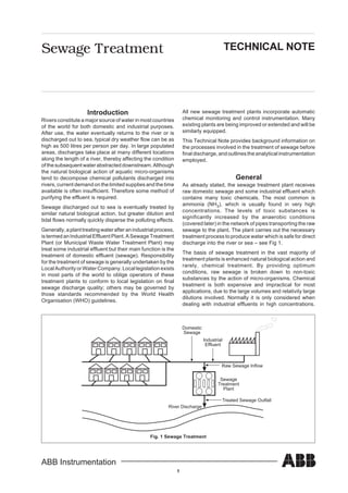
- 1. 1 ABB Instrumentation Sewage Treatment TECHNICAL NOTE Introduction Rivers constitute a major source of water in most countries of the world for both domestic and industrial purposes. After use, the water eventually returns to the river or is discharged out to sea, typical dry weather flow can be as high as 500 litres per person per day. In large populated areas, discharges take place at many different locations along the length of a river, thereby affecting the condition ofthesubsequentwaterabstracteddownstream.Although the natural biological action of aquatic micro-organisms tend to decompose chemical pollutants discharged into rivers, current demand on the limited supplies and the time available is often insufficient. Therefore some method of purifying the effluent is required. Sewage discharged out to sea is eventually treated by similar natural biological action, but greater dilution and tidal flows normally quickly disperse the polluting effects. Generally,aplanttreatingwaterafteranindustrialprocess, istermedanIndustrialEffluentPlant.ASewageTreatment Plant (or Municipal Waste Water Treatment Plant) may treat some industrial effluent but their main function is the treatment of domestic effluent (sewage). Responsibility for the treatment of sewage is generally undertaken by the Local Authority or Water Company. Local legislation exists in most parts of the world to oblige operators of these treatment plants to conform to local legislation on final sewage discharge quality; others may be governed by those standards recommended by the World Health Organisation (WHO) guidelines. Domestic Sewage Industrial Effluent Sewage Treatment Plant Raw Sewage Inflow River Discharge Treated Sewage Outfall Fig. 1 Sewage Treatment All new sewage treatment plants incorporate automatic chemical monitoring and control instrumentation. Many existing plants are being improved or extended and will be similarly equipped. This Technical Note provides background information on the processes involved in the treatment of sewage before final discharge, and outlines the analytical instrumentation employed. General As already stated, the sewage treatment plant receives raw domestic sewage and some industrial effluent which contains many toxic chemicals. The most common is ammonia (NH3), which is usually found in very high concentrations. The levels of toxic substances is significantly increased by the anaerobic conditions (covered later) in the network of pipes transporting the raw sewage to the plant. The plant carries out the necessary treatment process to produce water which is safe for direct discharge into the river or sea – see Fig 1. The basis of sewage treatment in the vast majority of treatment plants is enhanced natural biological action and rarely, chemical treatment. By providing optimum conditions, raw sewage is broken down to non-toxic substances by the action of micro-organisms. Chemical treatment is both expensive and impractical for most applications, due to the large volumes and relativity large dilutions involved. Normally it is only considered when dealing with industrial effluents in high concentrations.
- 2. 2 ABB Instrumentation However,someindustrieshavetheirowneffluenttreatment plant based on a biological process. Sewage treatment plants tend to conform to the same basic treatment processes, although they can differ depending on the nature of the effluent (i.e. floating material,suspendedanddissolvedsolids),concentrations of various chemicals, the relative dry and wet weather flows, and the legislation governing the treated sewage discharges. Sewage Treatment Process There are four main stages of treatment in a typical sewage treatment plant, but the design or layout can vary from site to site. These plants are categorised into one of three types, based on the method of secondary treatment, i.e. Biological Filter, Activated Sludge, and Pasveer Ditch. 1. Primary Treatment It is essential to remove large solids, e.g. road grit and silt from the raw sewage in order to prevent mechanical damage or blockages to pumps, valves, channels, and orifices.TheinitialstageofthePrimaryTreatmentincludes asettlingchannelortank,knownasGritRemoval,followed byscreening,toremovefloatingandlargeorganicmaterial. Coarse screens, generally bars with 6mm spacing, are followed by fine screens, and then drum filters. Screening may be combined with maceration, which involves shredding the raw sewage, followed by a process to crush the solids into very small particles. Fig. 2 Typical Sewage Treatment Process Raw Sewage Inflow Screens/Filters/Macerators Primary Sedimentation Tank PASVEER DITCH ACTIVATED SLUDGE BIOLOGICAL FILTRATION Treated Sewage Discharge Clarifier Clarifier Final Sedimentation Tank Filter SECONDARY TERTIARY PRIMARY Aerator Oxidation Ditch Humus Tank Biological Filters Activated Sludge Tank The screened sewage is then passed to a further tank, knownasSedimentation,tosettlethebulkofthesuspended matter. Colloidal and dissolved solids are not removed and require further treatment at the Secondary Treatment stage. 2. Secondary Treatment Biological Reactions The sewage consists of toxic chemicals both organic or inorganic. Organic waste, containing carbon, combined with other chemical elements, is broken down by the biological processes. This involves developing a culture of bacteriaandothermicro-organisms,whichinthepresence of sufficient oxygen, multiplies and feeds on the chemical substances in the sewage. Oxidation of the ammonia, for example, results in the conversion to nitrogen compounds, such as nitrite (NO2 – ), and with further oxidation, to nitrate (NO3 – ). This reaction is termed nitrification. Inorganic chemicals can also be treated, to a lesser extent by biological action, but they may require some form of chemical treatment. If the process is carried out correctly, the net result is a treated sewage which has a very low toxicity level, suitable for final discharge. The growth of the population of micro-organisms is determined by the availability of nutrient (provided by the raw sewage), temperature, pH, and (most importantly) dissolved oxygen. Optimum conditions vary according to the species, but are approximately 25 to 32°C, 5.5 to 9.5pH, and 2mgl -1 respectively.
- 3. 3 ABB Instrumentation Typical biochemical reactions produced by the action of micro-organisms on sewage are shown in Fig. 3. Both the Biological filter and the Pasveer Ditch systems, tendtobeusedonsmaller,ruraltreatmentplants.However, activated sludge treatment is employed in most modern plants throughout the world. a. Biological Filtration This consists of a large circular tank or series of tanks containing stone or plastic pieces which is sprayed with the screened sewage by a mechanical rotating arm moving over the surface of the bed. The medium is sufficiently loose to allow the liquid to permeate it and provide free access of air. A thin film of micro- organisms is then supported on the bed which provide biological decomposition of the sewage. The nature of the medium is critical to ensure an adequate retention time for maximum efficiency. The liquid leaving the bed passes to further settling or humus tanks, in which residual solids collect, and are withdrawn periodically for sludge disposal. Although this system has been in common use since the early 1900s, the disadvantage of the biological filter is mainly due to difficulties in control with variation in flow and concentration of the sewage, and its unsuitability for large scale treatment. b. Activated Sludge The activated sludge method, first instigated in 1914, involves developing a culture of bacteria and other organisms in a large tank and on lanes containing the settled sewage. Oxygen in the form of air or pure oxygenisforcedintothesewagebymechanicalmeans to sustain the oxidation process, More sludge is made every day than is actually needed to continue the process, so the surplus is pumped to the Sludge Treatment stage. The oxygen required for efficient oxidation is provided by one of two methods: i. Mechanical Aeration. Agitators are used on the surface of the tanks, the rate of aeration can be controlled by varying the speed or depth of immersion of the agitator, see Fig 4. In practice, many parallel lanes are often used with one or more agitators in each lane. Fig. 3 Biochemical Reactions Found in Surface Waters Aeration Lane Large Electric Motors Agitators Fig. 4 Mechanical Aeration AEROBIC REACTIONS with Oxygen Micro Organisms without Oxygen ANAEROBIC REACTIONS Polluting compound containing: Carbon, C Hydrogen, H Nitrogen, N Phosphorous, P Sulphur, S Non-toxic substances Carbon dioxide, CO2 Nitrate, NO3 – Phosphate, PO4 3– Sulphate, SO4 2– Water, H2 O Toxic substances Hydrogen Gas, H2 Methane gas, CH4 Hydrogen sulphide, H2 S Ammonia, NH3 Alcohols Toxic Organic Compounds
- 4. 4 ABB Instrumentation ii. Air/Oxygen Diffusion. Oxidation is achieved using perforated pipes or domes called, diffusers, positioned in the base of the tanks. Air or pure oxygen from compressors is pumped through these diffusers, producing small bubbles in the sewage, providing very efficient oxidation – see Fig 5. The rate of oxidation is then controlled by varying the speed of the compressors. c. Pasveer Ditch This system was developed only in 1953, and it is more widely employed in main land Europe than in the UK and the rest of the world. Basically, it consists of an oval-shaped channel, approximately 2 to 3 metres deep, into which sewage is passed after primary treatment. Based on the same biological processes as in activated sludge, the sewage is aerated and circulated around the ditch by means of one or more rotors mounted at different points around the ditch The depth of immersion, and speed of rotation, is adjusted to suit the oxygen demand of the sewage. The effluent is recirculated until adequate aeration is achieved before being passed to the settling tank, for tertiary treatment. One variation of the oval Pasveer Ditch design,isanarrangementwheretheditchisconstructed as one long channel, often in a zigzag layout to save space. Rotors are used in the same way to aerate and propel the sewage along the ditch as the biological process takes place. Aeration/Oxidation control In the case of the Activated Sludge and Pasveer Ditch, the volumes of air or oxygen required to treat sewage is large. By measuring the dissolved oxygen in the aeration/ oxidation lanes, careful control is kept of the volumes produced, limiting the value to around 2mgl -1 in the sewage sludge. This is just sufficient for the degree of treatment required and ensures that complete nitrification of the ammonia is achieved – see Fig 6. Air or pure oxygen Compressor Aeration Lane Diffusers Fig. 5 Oxygen/Air Diffusion Concentration mgl-1 Time NO3 – produced by oxidation of the ammonia O2 due to aeration NH3 in raw sewage Fig. 6 Nitrification of the Ammonia with Varying Levels of Aeration
- 5. 5 ABB Instrumentation 3. Tertiary Treatment Treated sewage from the secondary treatment is then passed for final clarification or filtration before discharge to the river or sea. The clarifier is a settling tank, similar to that used for primary treatment, and may be followed by a polishing filter. 4. Sludge Treatment The total recovered solids from the grit traps, screens, filters, surplus activated sludge, and settling tanks are passed periodically to the Sludge Treatment Plant. On older plants the sludge may be passed to large lakes or lagoons, from which the water is run off or allowed to evaporateslowly.Theremainingsolidsareburied,burned, or sold as fertiliser. Current practice involves dewatering of the sludge with filters before being passed on to digesters. Here, anaerobic micro-organisms flourish in warm conditions, breaking down any sludge into inorganic solids and methane gas. This gas can be used to provide power for electricity generation, to use on the site. Phosphate and Nitrate Reduction More complex activated sludge plants, precede the aeration/oxidation stage with phosphate and/or nitrate reduction stages. All three stages are normally carried out in a series of long partitioned lanes. The sewage flows over or under these partition walls, from one stage to the next – see Fig 7. Phosphate reduction is carried out to reduce the levels of phosphateinthefinalsewagetreatedeffluent.Itisachieved by the addition of Ferric Sulphate – Fe2(SO4)3 to the sewage, causing the phosphate to coagulate with the ferric. This forms a sludge with can then be easily settled and passed on to the Sludge Treatment stage . To provide better control of the aeration stage of the treatment process, some plants (pioneered in Germany) employ an anaerobic pretreatment stage. One effect of a pretreatment stage is to reduce the levels of nitrate found in the raw sewage. The reduction of nitrate provides a means of measuring the anaerobic process, resulting in effective control. The anaerobic conditions consume the oxygen bound up in the ions (NO3 – ) releasing nitrogen gas to the atmosphere. Methanol is added to the process to act as a nutrient to increase bacteria activity. Some treatment plants may carry out nitrate reduction after the aeration/oxidation stage to reduce the levels of nitrate in the final treated sewage. Anaerobic Aerobic Ferric Sulphate Partition Walls Air/Oxygen Oxidation stageNitrate reductionPhosphate reduction Methanol Fig. 7 Treatment Plant including Phosphate and Nitrate Reduction Stages
- 6. 6 ABB Instrumentation Instrumentation Instrumentation on sewage plants is dependent on the size of the plant and the type of control required. Automatic monitoring and control instrumentation must be used to ensurethattheoptimumprocessconditionsaremaintained, and its use becomes essential with the introduction of more stringent controls on discharge into water courses – see Table 1. As well as improving the control and the final sewage effluent quality from the plant, operating costs can also be significantly reduced. Asalreadystated,DissolvedOxygenmonitorsareessential to provide optimum control of the aeration/oxidation stage of the treatment process. Many motors or compressors are used on large treatment plants which can consume several hundred kW, so by incorporating careful control, substantial savings in electricity costs can be achieved. Even on small treatment plants, significant saving can be achieved by careful control. Ammonia monitors are often installed on the final effluent stream to ensure the discharge limits have been met and also as an indication of the process efficiency. However, if phosphate or nitrate reduction is employed, this again requires process monitoring and control. Suspended Solids monitors are invaluable throughout the plant to indicate load, efficiency and correct operation of each stage of the process pH is often used to monitor the raw sewage to guard against acidic or alkaline effluent entering the plant which could upset, or in severe circumstances, kill the micro- organisms used to carry out biological reaction. pH and conductivity systems could also be employed to monitor particular treatment processes. Biological Oxygen Demand (BOD) , which gives an indication of the amount of organic matter entering the plant, is normally measured in the laboratory, but on-line analysers are becoming more common. Table 1 Typical Measurement Points tnalpehtniegatS tnemerusaeM esopruP .ytivitcudnoC&Hp lairtsudnielbatpeccanumorfssecorpehttcetorpoT segrahcsid yramirP .sdilosdednepsus&ainommA .gnidaoltnalprotinomoT sdilosdednepsuS sknatgnilttesmorfegrahcsidrotinomoT ainommA&negyxOdevlossiD noitadixo/noitarealortnocoT yradnoceS etartiN&etahpsohP erasegatsesehtfi,ssecorplavomerrotinomoT tnalpehtfongisedehtnidetaroprocni sdilosdednepsuS sknatnoitatnemidesmorfegrahcsidrotinomoT .noitartlifro/dna yraitreT &etahpsohP,etartiN,ainommA DOB,sdilosdednepsuS ehtdnatnalpehtfoecnamrofrepehtrotinomoT .ytilauqegawesdetaertlanif Technical Support Department February 1998