

Recommended
Recommended
More Related Content
What's hot
What's hot (20)
Similar to 04 ret670 test report
Similar to 04 ret670 test report (20)
Recently uploaded
Recently uploaded (20)
04 ret670 test report
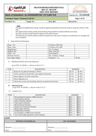
- 1. TRANSFORMER DIFFERENTIAL RELAY- RET670 SITE TEST REPORT Name of Substation: AL-GHASSANIYAH 115/13.8kV S/S Contract No. : 31131093/00 Customer Name: National Grid-SA Page 1 of 15 Panel/Bay No.: Equip. No.: Dwg. Ref.: Record No.: DATE: TESTING ENGINEER-JAL CSD- ENGINEER Signature: ________________ Signature: ________________ Name : ________________ Name : ________________ Note: − The approved updated final settings should be applied and printed out from the relay by using the software of the relay. − The approved final setting and the printout final setting should be attached with this test format. − The print out final setting should be signed by NG and Contractor. − The following test format contains minimum required tests and some of settings are mentioned as an example and not as limitation. 1. General Data & Information 2. Mechanical Checks and Visual Inspection As per TCS –P–105 Rev -1, Item no 4.1& 4.12.1.1 ITEM DESCRIPTION REMARKS 1. Inspect for any physical damage or defects. Yes N/A 2. Verify connections and ferrules as per approved drawings Yes N/A 3. Check tightness of all the connections. Yes N/A 4. Check Apparatus List Yes N/A 5. Check relay version and switching elements on printed circuit board Yes N/A 3. Electrical Tests As per TCS –P–105 Rev -1, Item no 4.2& 4.12.1.2 3.1. Function Test ITEM DESCRIPTION REMARKS 1. Human Machine Interface (HMI) Checked. Yes N/A 2. Case Earthing checked. Yes N/A 3. LED’s Function Checked. Yes N/A 4. Trip Contacts Checked. Yes N/A 5. Reset Function Checked Yes N/A 6. Group active Functions Checked Yes N/A 7. Binary inputs checked. Yes N/A 8. Output Relays Checked Yes N/A 9. Event Display on HMI Screen Checked Yes N/A 10. Test switch / plug checked for correct function. Yes N/A Panel No. CT Ratio of HV Side Relay Type CT Ratio of LV Side Manufacturer No. of contacts: SERIAL NO Draw. & Sh No. : Order - No. Conn.Diag.No. Software Version DC. Auxiliary. Voltage pto-coupler supply: Frequency Fn 60 Hz
- 2. TRANSFORMER DIFFERENTIAL RELAY- RET670 SITE TEST REPORT Name of Substation: AL-GHASSANIYAH 115/13.8kV S/S Contract No. : 31131093/00 Customer Name: National Grid-SA Page 2 of 15 Panel/Bay No.: Equip. No.: Dwg. Ref.: Record No.: DATE: TESTING ENGINEER-JAL CSD- ENGINEER Signature: ________________ Signature: ________________ Name : ________________ Name : ________________ 11. Watchdog contacts checked Yes N/A 12. Current shorting facility. Yes N/A 3.2. Operating DC supply current DC voltage (V) DC current w/o fault (mA) DC current with fault(mA) Max. calculated watt (W) + - Limit: DC burden 50 watts. (Refer to the reference technical manual page 391). 3.3. Watch Dog Check A. Supply OFF TERMINALS (CLOSED) - :(X11:2,X11:3) : TERMINALS (OPEN) - :( X11:2 X11:1) : B. SUPPLY ON TERMINALS (CLOSED) - :( X11:1, X11:2) : TERMINALS (OPEN) - :(X11:3, X11:2) : 3.4. Time and Date Check:- To check time &date go to main menu on the display for RET670 then system time and adjust time &date. To test this, remove the auxiliary supply from the relay for approximately 30 seconds, then restoring the auxiliary supply, the time and date should be correct. Result: ____________ 3.5. Setting Adopted: Transformer Data: (All Values as an example) Winding 1 ( HV ) Winding 2 ( LV ) Winding 3 (Tertiary.) Connection Type Y0 y0 d1 Capacity ( MVA ) 60 60 Rated Voltage ( KV ) 132 13.8 Rated Current ( A ) 262 2510 CT Data: CT 1 ( HV ) CT 2 ( LV ) CT 3 (Tertiary.) Connection Type Y y Primary Current ( A ) 300 3000 Secondary Current (A ) 1 1 Calculated Amplitude Matching Factor (K): KX = CTX / Rated_Current_Of_Ref.Wdg Where Ref.Wdg is First Wdg with Y connection. if no Y connection then HV side selected automatically
- 3. TRANSFORMER DIFFERENTIAL RELAY- RET670 SITE TEST REPORT Name of Substation: AL-GHASSANIYAH 115/13.8kV S/S Contract No. : 31131093/00 Customer Name: National Grid-SA Page 3 of 15 Panel/Bay No.: Equip. No.: Dwg. Ref.: Record No.: DATE: TESTING ENGINEER-JAL CSD- ENGINEER Signature: ________________ Signature: ________________ Name : ________________ Name : ________________ KHV = 1.14 KLV = 1.19 KTerit. = General Differential Equation: Where 1. is Differential Current 2. is Differential Current Contribution from W1 side 3. is Differential Current Contribution from W2 side 4. is Differential Current Contribution from W3 side A, B, C is a coefficients depended on vector group; refer to Manual to get exact value. 3.6. Secondary Injection Tests: (All Values as an example) 3.6.1. Measurements (HV side): TRM P40 - 9I+3U Channel DUTY CTR Injected Values Measured Values REMARKS Primary Sec CH 1-I W1 CT IL1 CH 2-I W1 CT IL2 CH 3-I W1 CT IL3 CH 4-I W1 CT IN CH 5-I W2 CT IN CH 6-I W2 CT IL1 CH 7-I W2 CT IL2 CH 8-I W2 CT IL3 CH 9-I Spare CH 10-U W1 VT Ph-R CH 11-U W1 VT Ph-R CH 12-U W1 VT Ph-R TRM P41 – 6I+6U CH 1-I Spare CH 2-I Spare CH 3-I Spare CH 4-I Spare CH 5-I Spare
- 4. TRANSFORMER DIFFERENTIAL RELAY- RET670 SITE TEST REPORT Name of Substation: AL-GHASSANIYAH 115/13.8kV S/S Contract No. : 31131093/00 Customer Name: National Grid-SA Page 4 of 15 Panel/Bay No.: Equip. No.: Dwg. Ref.: Record No.: DATE: TESTING ENGINEER-JAL CSD- ENGINEER Signature: ________________ Signature: ________________ Name : ________________ Name : ________________ CH 6-I Spare CH 7-U Spare CH 8-U Spare CH 9-U Spare CH 10-U Spare CH 11-U Spare CH 12-U Spare Limits: Amplitude Accuracy; ± 0.5 % Ir According to the Catalogue for Technical Data Page: 32 3.6.2. Pick- up & Drop- off Test For Differential Current (Id): • This is single phase injection test. • Disable SOTF facility. Disable any Negative Sequence facility • Disable zero Sequence removing facility. Apply equation at page 3 the Diff. Eq. for single phase injection, 2 winding will be: IDLx = A . KHV . Iw1Lx + B .( U2/U1) . KLV. Iw2L Where x represents the concerted phase HV Winding Phase Id min. Set Value Calculated value (A) Measured Value ( A ) Drop Out PickUp Ratio Operating Time @ 2X I pickup (ms) Pick up Drop out R 0.1 0.087 0.3 0.262 0.5 0.437 Y 0.1 0.087 0.3 0.262 0.5 0.437 B 0.1 0.087 0.3 0.262 0.5 0.437
- 5. TRANSFORMER DIFFERENTIAL RELAY- RET670 SITE TEST REPORT Name of Substation: AL-GHASSANIYAH 115/13.8kV S/S Contract No. : 31131093/00 Customer Name: National Grid-SA Page 5 of 15 Panel/Bay No.: Equip. No.: Dwg. Ref.: Record No.: DATE: TESTING ENGINEER-JAL CSD- ENGINEER Signature: ________________ Signature: ________________ Name : ________________ Name : ________________ LV Winding Phase Id min. Set Value Calculated value ( A ) Measured Value ( A ) Drop Out Pickup Ratio Operating Time @ 2X I pickup (ms) Pick up Drop out R 0.1 0.084 0.3 0.251 0.5 0.418 Y 0.1 0.084 0.3 0.251 0.5 0.418 B 0.1 0.084 0.3 0.251 0.5 0.418 Limits: Pick up & Drop Out ±2% of Ir for I < Ir or ±2% of I for I > Ir, Reset Ratio > 95%, Timing tolerance Typically 25 ms for 2 Id, and 12 ms for 5 Id for unrestrained function , According to the Catalogue for Technical Data Page: 143 3.6.3. Pick-up & Drop-off Test for Unrestrained Differential Current (id): H.V Winding Phase Set Value Calculated value ( A ) Measured Value ( A ) Drop Out Pickup Ratio Operating Time @ 5X I pickup (ms) Pick up Drop out R 2.00 1.754 3.00 2.631 5.00 4.385 Y 2.00 1.754 3.00 2.631 5.00 4.385 B 2.00 1.754 3.00 2.631 5.00 4.385
- 6. TRANSFORMER DIFFERENTIAL RELAY- RET670 SITE TEST REPORT Name of Substation: AL-GHASSANIYAH 115/13.8kV S/S Contract No. : 31131093/00 Customer Name: National Grid-SA Page 6 of 15 Panel/Bay No.: Equip. No.: Dwg. Ref.: Record No.: DATE: TESTING ENGINEER-JAL CSD- ENGINEER Signature: ________________ Signature: ________________ Name : ________________ Name : ________________ L.V Winding Phase Set Value Calculated value ( A ) Measured Value ( A ) Drop Out Pickup Ratio Operating Time @ 5X I pickup (ms) Pick up Drop out R 2.00 1.678 3.00 2.517 5.00 4.195 Y 2.00 1.678 3.00 2.517 5.00 4.195 B 2.00 1.678 3.00 2.517 5.00 4.195 3.6.4. BIAS CHARACTERISTIC TESTING Inject H.V and L.V phase with equal current on each, and angle 0 for H.V and 180 for L.V, then decrease L.V Phase until trip, while leave H.V with fixed current which will be the bias current, and record values and check that corresponds to following equation.
- 7. TRANSFORMER DIFFERENTIAL RELAY- RET670 SITE TEST REPORT Name of Substation: AL-GHASSANIYAH 115/13.8kV S/S Contract No. : 31131093/00 Customer Name: National Grid-SA Page 7 of 15 Panel/Bay No.: Equip. No.: Dwg. Ref.: Record No.: DATE: TESTING ENGINEER-JAL CSD- ENGINEER Signature: ________________ Signature: ________________ Name : ________________ Name : ________________ a. Section 1 (All Values as an example) Where bias current is between: 0 ≤ Ibias ≤ Endsection1 Idmin = 0.3 , Set End section1 = 1.25 Slope section1 I bias (A) IH.V (A) Expected IL.V (A) Id calculated Measured IL.V (A) Errors % R Y B R Y B Idmin 0.3 0.262 0 0.3 0.4 0.350 0.084 0.3 1.00 0.875 0.586 0.3 Limits; ± 2 %Ir According to the Technical Reference Catalogue – Page24 b. SLOPE Section 2 (All Values as an example) When bias current is between: Endsection1 ≤ Ibias ≤ Endsection2 Trip Id = (Idmin + slope section2/100 *(Ibias - End section1) A Where; Idmin ; The Basic Diff Current Setting. To check more than one point at the same slope, Change the bias current value and the equation above can be used, and also for other differential settings '' Different slopes, Is1 ''. Apply the above procedure for each phase. Set Idmin = 0.3 End section1 = 1.25 End section2 =3.0 Slope section 2 = 40% Ibias A IH.V = Ibias / kHV A Expected IL.V = (Ibias – Id) / kLV (A) Id calculated Measured IL.V (A) Errors % R Y B R Y B 1.25 1.093 0.795 0.300 1.50 1.312 0.920 0.400 1.75 1.531 1.046 0.500 2.00 1.750 1.171 0.600 2.25 1.968 1.297 0.700 2.50 2.187 1.422 0.800 Limits; ± 2 %Ir According to the Technical Reference Catalogue – Page24
- 8. TRANSFORMER DIFFERENTIAL RELAY- RET670 SITE TEST REPORT Name of Substation: AL-GHASSANIYAH 115/13.8kV S/S Contract No. : 31131093/00 Customer Name: National Grid-SA Page 8 of 15 Panel/Bay No.: Equip. No.: Dwg. Ref.: Record No.: DATE: TESTING ENGINEER-JAL CSD- ENGINEER Signature: ________________ Signature: ________________ Name : ________________ Name : ________________ c. SLOPE Section3 (All Values as an example) Repeat the test and check the result with the following equation; When bias current is more than: Ibias ≥ End section2 Trip Id = (Idmin + slope section2/100*(End section2 - End section1)) + (Slope section3/100 * (Ibias- End section2)) A Set End section1 = 1.25 End section2 =3.0 Slope section1 = 40% Slope section2 = 80% Idmin = 0.3 I bias A IH.V = Ibias / kHV A Expected IL.V = (Ibias – Id) / kLV (A) Id calculated Measured IL.V (A) Errors % R Y B R Y B 3.0 2.624 1.673 1.000 3.5 3.062 1.757 1.400 4.0 3.499 1.841 1.800 4.5 3.936 1.925 2.200 5.0 4.374 2.008 2.600 6.0 5.249 2.176 3.4 Limits; ± 2 %Ir According to the Technical Reference Catalogue – Page24 3.6.5. Test of 2nd Harmonics (All Values as an example) Idmin = 0.3 Ib Phase I2 / I1 ratio % I1 ( F =60 Hz ) (Pickup Value) I2 ( F = 120 Hz ) Expected Blocking Measured R 10 0.300 0.030 Y 50 0.300 0.150 B 100 0.300 0.300 3.6.6. Test of 5th Harmonics Phase I5 / I1 ratio % I1 ( F =60 Hz ) I5 ( F = 300 Hz ) Expected Blocking Measured R 15 0.300 0.045 Y 30 0.300 0.090 B 50 0.300 0.150
- 9. TRANSFORMER DIFFERENTIAL RELAY- RET670 SITE TEST REPORT Name of Substation: AL-GHASSANIYAH 115/13.8kV S/S Contract No. : 31131093/00 Customer Name: National Grid-SA Page 9 of 15 Panel/Bay No.: Equip. No.: Dwg. Ref.: Record No.: DATE: TESTING ENGINEER-JAL CSD- ENGINEER Signature: ________________ Signature: ________________ Name : ________________ Name : ________________ 3.6.7. Cross Block test Winding IR IY IB Cross Block on Cross Block Off HV I > pickup with 2nd harmonic I > pickup without 2nd harmonic I > pickup with 2nd harmonic I > pickup without 2nd harmonic I > pickup without 2nd harmonic I > pickup with 2nd harmonic l.V I > pickup with 2nd harmonic I > pickup without 2nd harmonic I > pickup with 2nd harmonic I > pickup without 2nd harmonic I > pickup without 2nd harmonic I > pickup with 2nd harmonic Test done at I2/I1= 15%, I5/I1 = 25 % 3.6.8. SOTF test: This function used when energized the transformer with internal fault. where it use current gap principle to overridden all harmonic and waveform block and trip quickly. To test it , enable SOTF function and inject phase with harmonic and current over pickup value …. at two condition : a) Direct injection expected : Trip Status ___________ b) 2 stage , 1st state normal load without trip ( note : inject current from both side H.V and L.V to simulate the normal load ) and 2nd state with value over pickup and have a 2nd harmonic over I2/I1 setting . Expected: Block Status ___________ 3.6.9. Negative Sequence test: (All Values as an example) a. IminNegSeq test : INegSeq. =1/3 { IR + a2 IY + a IB } , where a = °∠1201 Irelay = Iinject * K And we at test inject single phase then : Irelaynegseq = 1/3 Iinject * K IMinNegSeq setting IH.V ( > IMinNegSeq setting ) (A) Expected IL..V (A) Measured IL..V (A) 0.04 0.11 0.100 0.08 0.22 0.201 0.10 0.27 0.252
- 10. TRANSFORMER DIFFERENTIAL RELAY- RET670 SITE TEST REPORT Name of Substation: AL-GHASSANIYAH 115/13.8kV S/S Contract No. : 31131093/00 Customer Name: National Grid-SA Page 10 of 15 Panel/Bay No.: Equip. No.: Dwg. Ref.: Record No.: DATE: TESTING ENGINEER-JAL CSD- ENGINEER Signature: ________________ Signature: ________________ Name : ________________ Name : ________________ b. Negative sequence Relay Operating Angle (NegSeqROA ) test : Inject H.V & L.V > IMinNegSeq Inject H.V with angle zero degree and change the L.V to get the operating zone. Neg.Seq.ROA setting Expected IL..V angle for operating zone (Deg) Measured IL..V angle for operating zone (Deg) 30 330 – 30 40 320 – 40 80 280 – 80 c. Sensitive negative sequence (turn-to-turn falut ) test: This function based on Negative sequence discriminator. where if there is no start signal ( independent on existence or not for start signal ) and the fault is classified as internal fault and at same time for H.V and L.V sides the negative sequence current is greater than IminNegSeq .. then trip transformer To test it , inject single phase from 2 winding in phase and increase them at same time until trip , ( must happen by ssneg only not restrain function ) . Status ____________________ 3.6.10. Unrestrained negative sequence test: Any start signal activate that function (i.e function independent on start signal ), where if the fault discriminate as internal fault then remove any harmonic which block relay and trip quickly , And if fault discriminate as external fault. Then if the signal is polluted with harmonics this will block relay else request trip. Internal fault action (Expected: Trip): _____________ External fault (with harmonics) action (Expected: Block) : External fault (without harmonics) action (Expected: Trip): 3.7. FINAL SETTING: (All values as an example) Power Transformer Configuration Rated Voltage W1 Rated Voltage W2 Rated Current W1 Rated Current W2 W1 Connection Type W2 Connection Type W2 Clock Number ZS CurrSubtr W1 ZS CurrSubtr W2 ZS CurrSubtr W3 T configuration of W1 CT1 Rating W1 CT2 Rating W1 T configuration of W2 CT1 Rating W2 CT2 Rating W2
- 11. TRANSFORMER DIFFERENTIAL RELAY- RET670 SITE TEST REPORT Name of Substation: AL-GHASSANIYAH 115/13.8kV S/S Contract No. : 31131093/00 Customer Name: National Grid-SA Page 11 of 15 Panel/Bay No.: Equip. No.: Dwg. Ref.: Record No.: DATE: TESTING ENGINEER-JAL CSD- ENGINEER Signature: ________________ Signature: ________________ Name : ________________ Name : ________________ Differential Characteristics Configuration Idmin: End section1: End section2: Slope section2: Slope section3: Id Unre: I2/I1 Ratio: I5/I1 Ratio: Idiff Alarm: tAlarm delay: Op Neg. Seq. Diff I min Neg. Seq. Neg Sequence ROA SOTF Cross Blocking 3.7.1. PICK UP & DROP OFF TEST FOR DIFFERENTIAL CURRENT (Id): From eq. at page 2 the Diff. Eq. for single phase injection, 2 windge will be: IDLx = A * Iw1Lx + (U2/U1) * B * Iw2Lx And after applying zero sequence removing facility then - H.V side: I relay = I inject * (2 / 3) * KH.v . Where KH.v = - L.V side: I relay = I inject * (2 / 3) * KL.v where KL.v = Where x represent the concerted phase HV Winding Phase Id min. Set Value Calculated value Measured Value Drop Out PickUp Ratio Operating Time @ 2X I pickup (ms) Pick up Drop out R Y B
- 12. TRANSFORMER DIFFERENTIAL RELAY- RET670 SITE TEST REPORT Name of Substation: AL-GHASSANIYAH 115/13.8kV S/S Contract No. : 31131093/00 Customer Name: National Grid-SA Page 12 of 15 Panel/Bay No.: Equip. No.: Dwg. Ref.: Record No.: DATE: TESTING ENGINEER-JAL CSD- ENGINEER Signature: ________________ Signature: ________________ Name : ________________ Name : ________________ LV Winding Phase Id min. Set Value Calculated value Measured Value Drop Out PickUp Ratio Operating Time @ 2X I pickup (ms) Pick up Drop out R Y B Limits: Pick up & Drop Out ±2% of Ir for I < Ir or ±2% of I for I > Ir, Reset Ratio > 95%, Timing tolerance Typically 25 ms, According to the Catalogue for Technical Data Page: 143 Pick-up & Drop-off Test for Unrestrained Differential Current (Id): HV winding Phase Iunrest. Set Value Calculated value Measured Value Drop Out PickUp Ratio Operating Time @ 2X I pickup (ms) Pick up Drop out R Y B LV Winding Phase Iunrest. Set Value Calculated value Measured Value Drop Out PickUp Ratio Operating Time @ 2X I pickup (ms) Pick up Drop out R Y B Limits: Pick up & Drop Out ±2% of Ir for I < Ir or ±2% of I for I > Ir, Reset Ratio > 95%, Timing tolerance Typically 25 ms, According to the Catalogue for Technical Data Page: 143 3.7.2. BIAS CHARACTERISTIC TESTING Section 1 When bias current is between: 0 ≤ Ibias ≤ Endsection1 Slope section1 I bias A IH.V A Expected IL.V (A) Id calculated Measured IL.V (A) Errors % R Y B R Y B Idmin
- 13. TRANSFORMER DIFFERENTIAL RELAY- RET670 SITE TEST REPORT Name of Substation: AL-GHASSANIYAH 115/13.8kV S/S Contract No. : 31131093/00 Customer Name: National Grid-SA Page 13 of 15 Panel/Bay No.: Equip. No.: Dwg. Ref.: Record No.: DATE: TESTING ENGINEER-JAL CSD- ENGINEER Signature: ________________ Signature: ________________ Name : ________________ Name : ________________ Limits; ± 2 %Ir According to the Technical Reference Catalogue – Page24 SLOPE Section 2 When bias current is between: Endsection1 ≤ Ibias ≤ Endsection2 Trip = (Idmin + slope section2/100 *(Ibias - End section1) A I bias A IH.V A Expected IL.V (A) Id calculated Measured IL.V (A) Errors % R Y B R Y B Limits; ± 2 %Ir According to the Technical Reference Catalogue – Page24 SLOPE Section3 When bias current is more than: Ibias ≥ End section2 Trip = (Idmin + slope section2/100*(End section2 - End section1)) + (Slope section3/100 * (Ibias- End section2) A I bias A IH.V A Expected IL.V (A) Id calculated Measured IL.V (A) Errors % R Y B R Y B Limits; ± 2 %Ir According to the Technical Reference Catalogue – Page24 3.7.3. Test of 2nd Harmonics Phase I2 / I1 ratio % I1 ( F =60 Hz ) (Pickup Value) I2 ( F = 120 Hz ) Expected Blocking Measured R Y B
- 14. TRANSFORMER DIFFERENTIAL RELAY- RET670 SITE TEST REPORT Name of Substation: AL-GHASSANIYAH 115/13.8kV S/S Contract No. : 31131093/00 Customer Name: National Grid-SA Page 14 of 15 Panel/Bay No.: Equip. No.: Dwg. Ref.: Record No.: DATE: TESTING ENGINEER-JAL CSD- ENGINEER Signature: ________________ Signature: ________________ Name : ________________ Name : ________________ 3.7.4. Test of 5th Harmonics Phase I5 / I1 ratio % I1 ( F =60 Hz ) I5 ( F = 300 Hz ) Expected Blocking Measured R Y B 3.7.5. Negative Sequence test: IminNegSeq test: IMinNegSeq setting Expected IH.V (A) Expected IL.V (A) Measured IL.V (A) Measured IH.V (A) Negative sequence Relay Operating Angle (NegSeqROA ) test : Inject H.V & L.V > IMinNegSeq Inject H.V with angle zero degree and change the L.V to get the operating zone. NegSeqROA setting Expected IL..V angle for operating zone (Deg) Measured IL..V angle for operating zone (Deg) 3.7.6. Sensitive negative sequence (turn-to-turn falut) test: Status ____________________ 3.7.7. Unrestrained negative sequence test: Internal fault action (Expected: Trip): _____________ External fault (with harmonics) action (Expected: Block) : External fault (without harmonics) action (Expected: Trip): ____Trip indication test: ____ No. Type of fault Led Color Check
- 15. TRANSFORMER DIFFERENTIAL RELAY- RET670 SITE TEST REPORT Name of Substation: AL-GHASSANIYAH 115/13.8kV S/S Contract No. : 31131093/00 Customer Name: National Grid-SA Page 15 of 15 Panel/Bay No.: Equip. No.: Dwg. Ref.: Record No.: DATE: TESTING ENGINEER-JAL CSD- ENGINEER Signature: ________________ Signature: ________________ Name : ________________ Name : ________________ 3.7.8.Disturbance recorder checked [ ]. 3.7.9.Binary outputs and inputs checked [ ]. 3.7.10. Attach the Final setting print out of relay: 3.8. Test Equipment Used Sl. No Description Make Equipment Sl. No Calibration Date Calibration Due Date 1 2 3