
Recommended
More Related Content
What's hot
What's hot (20)
Similar to Hydraulic control system
Similar to Hydraulic control system (20)
More from nagaraju kondrasi
Recently uploaded
Recently uploaded (20)
Hydraulic control system
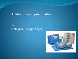
- 1. Hydraulics and pneumatics By K.Nagaraju (15311A03J2)
- 2. Hydraulic System •A Hydraulic System is a power Transmission System in which the transmission of power takes place through a fluid medium. •A hydraulic drive system is a quasi-hydrostatic drive or transmission system that uses pressurized hydraulic fluid to power hydraulic machinery. •Hydraulic System is most convenient and efficient System.
- 3. PRINCIPLE OF HYDRAULIC SYSTEM • The Hydraulic System works on the principle of Pascal’s law. • Pascal’s law states that “The pressure in an enclosed fluid is uniform in all the directions”.
- 4. COMPONENTS OF HYDRAULIC SYSTEM The major components of a hydraulic system are: 1. Prime Mover 2. Pump 3. Control Valves 4. Actuators(Hydraulic motors, pistons) 5. Piping System 6. Fluid
- 6. I. PRIME MOVERS •Prime mover is a device which develops the mechanical power. • This power in a hydraulic system is basically used to drive the pump. • Prime mover includes IC Engine, Turbines, etc
- 8. II. HYDRAULIC PUMPS • Pump is a device which converts mechanical energy to fluid energy. • The hydraulic pump takes hydraulic fluid (mostly some oil) from the storage tank and delivers it to the rest of the hydraulic circuit. • The hydraulic pumps are characterized by its flow rate capacity, power , consumption, drive speed, pressure delivered at the outlet and efficiency of the pump.
- 10. TYPES OF HYDRAULIC PUMPS Non-positive displacement pumps: •Known as hydro-dynamic pumps •Fluid is pressurized by the rotation of the propeller and the fluid pressure is proportional to the rotor speed •Used for low-pressure and high-volume flow applications Eg: Centrifugal Pumps Positive displacement pumps: •These pumps deliver a constant volume of fluid in a cycle •Used in most of the industrial fluid power applications •The output fluid flow is constant and is independent of the system pressure •Eg: Vane pump, Piston Pump, Gear Pump
- 13. III. CONTROL VALVES •The control of the mechanical outputs (motion and force) is one of the most important functions in a hydraulic system. • The proper selection of control selection ensures the desired output and safe function of the system. • In order to control the hydraulic outputs, different types of control valves are required. • There are basically three types of valves employed in hydraulic systems: 1. Directional control valves 2. Flow control valves 3. Pressure control valves
- 14. DIRECTIONAL CONTROL VALVES • Directional control valves provide the direction to the fluid and allow the flow in a particular direction. • These valves are used to control the start, stop and change in direction of the fluid flow. • They can be classified in the following manner: Type of construction: 1. Poppet valves 2. Spool valves Number of ports and switching positions: 1. Three way two position 2. Four way three position 3. Four way two position Method of change over from one position to next: 1. Non throttling type 2. Throttling type
- 15. FLOW CONTROL VALVES • A flow control valve can regulate the flow or pressure of the fluid. • The fluid flow is controlled by varying area of the valve opening through which fluid passes.
- 16. IV. HYDRAULIC ACTUATORS •Hydraulic Actuators employ hydraulic pressure to drive an output member. • These are used where high speed and large forces are required. • The fluid used in hydraulic actuator is highly incompressible. •They convert fluid power into mechanical power. • Depending on motion they can be classified as: 1. Linear actuators: linear motion as output(cylinder and piston) 2. Rotary actuator: rotary motion as output(motor
- 17. V. HYDRAULIC FLUID •Hydraulic fluid must be essentially non-compressible to be able to transmit power instantaneously from one part of the system to another. • At the same time, it should lubricate the moving parts to reduce friction loss and cool the components so that the heat generated does not lead to fire hazards. •The most common liquid used in hydraulic systems is petroleum oil because it is only very slightly compressible. Properties of hydraulic fluids: 1. Non compressible 2. Low volatility 3. Corrosion control 4. Fire resistance 5. Low toxicity 6. Good lubricator
- 18. VI. FILTERS The hydraulic fluid is kept clean in the system with the help of filters and strainers. • It removes minute particles from the fluid, which can cause blocking of the orifices of servo-valves or cause jamming of spools. • Types of hydraulic filters: 1. Suction Filters: The suction filter provides protection to the hydraulic pump from particles larger than 10 microns. 2. Pressure Side Filters: Located downstream from the hydraulic pump, these filters are designed to clean the fluid as it exits the pump to protect more sensitive system components such as control valves and actuators from contaminants generated from the pump.
- 19. 3. Return Side Filter: Located between the control valve and the fluid reservoir, these filters are designed to capture wear debris from the hydraulic systems working components before returning the fluid back to the reservoir 4.Offline Filter: These filters are used, independent from the hydraulic system, to clean hydraulic fluid before it enters the hydraulic system itself
- 20. VII. ACCUMULATORS •Accumulator are a common part of hydraulic machinery. Their function is to store energy by using pressurized gas. One type is a tube with a floating piston. On one side of the piston is a charge of pressurized gas, and on the other side is the fluid. Bladders are used in other designs. Reservoirs store a system's fluid. •Examples of accumulator uses are backup power for steering or brakes, or to act as a shock absorber for the hydraulic circuit
- 21. APPLICATIONS OF HYDRAULIC SYSTEMS • Industrial: Plastic processing machineries, steel making and primary metal extraction applications, automated production lines, machine tool industries, paper industries, loaders, crushes, textile machineries, R & D equipment and robotic systems etc. • Mobile hydraulics: Tractors, irrigation system, earthmoving equipment, material handling equipment, commercial vehicles, tunnel boring equipment, rail equipment,building and construction machineries and drilling rigs etc. • Automobiles: It is used in the systems like breaks, shock absorbers, steering system, wind shield, lift and cleaning etc. • Marine applications: It mostly covers ocean going vessels, fishing boats and navel equipment. • Aerospace equipment: There are equipment and systems used for rudder control, landing gear, breaks, flight control and transmission etc. which are used in airplanes, rockets and spaceships.
- 22. Pneumatics
- 23. What are Pneumatics Pneumatics is a type of power transmission that uses a gas ( in our case, air) and pressure differential to create movement. Akin to Hydraulics, hydraulics use oil, water, or other fluids instead of gases
- 24. A “System” is a complete set of parts working together. Our systems usually contain : A compressor Storage tanks Regulators Gauges Valves and solenoids Actuators Fittings and tubing The Pneumatics System
- 26. Parts of the “System” Pt.1 The compressor: •Heart of the system. •Converts electrical energy to pneumatic potential. •Contains a relief valve protects compressor and system from overload •Controlled by a Spike relay
- 27. Air tanks: Stores pressure to activate actuators Our robots can have up to 2 (included in the KOP) Pressure Switch: Used to signal Robot Controller when to turn on and off compressor
- 28. Regulators: Adjust pressure output to working levels for actuators 2 types : Relieving and Non- Relieving Fittings: Quick release and pipe thread. Pipe thread requires Teflon tape
- 29. Valves and Solenoids: Used to control actuators Types: Double Solenoid (detented) Single Solenoid (spring offset)
- 30. Actuators Linear – Often called cylinders – can be made to perform complex motions by using mechanical components Rotary Limited Rotation Self-contained Rack and pinion or lever Air Motors or turbines Clamps
- 31. Actuators Operation with Flow Controls Typically Flow Controls are mounted between the valve and the cylinder as close to the cylinder as practical The check valve permits free flow into the cylinder from the valve and metered flow from the cylinder to exhaust