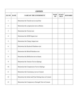
Tiruchengode – Sankari Mani Rd, Pullipalayam, Morur (PO), Sankari (Tk), Salem 637304.
B.E AGRICULTURE ENGINEERING – IV SEMESTER
Anna University - Regulation: 2017
CE 8481 - STRENGTH OF MATERIALS LABORATORY
SRI SHANMUGHA COLLEGE OF ENGINEERING AND TECHNOLOGY
(Approved By AICTE, Accredited by NAAC, Certified by ISO 9001:2015
& Affiliated to Anna University)
MATERIALS LABORATORY
MANUAL
CE8481-STRENGTH OF
DEPARTMENT OF AGRICULTURE ENGINEERING
SRI SHANMUGHA COLLEGE OF ENGINEERING AND TECHNOLOGY
ISO 9001:2008
Certified
REG NO.
Semester……………………………………………….Branch during the Academic year……………
in the…………………………………………………………………………………………..laboratory.
(Approved By AICTE, New Delhi & Affiliated to Anna University)
Tiruchengode – Sankari Mani Rd,Pullipalayam, Morur (PO),
Sankari(Tk), Salem (Dt) Pin : 637304.
RECORD NOTE BOOK
Certified that this is a bonafide record of Practical work done by
Mr/Ms/Mrs……………………………………………………of the………………………………………………
Staff – in – Charge Head of the Department
Internal Examiner External Examiner
GENERAL INSTRUCTIONS
 All the students are instructed to wear protective uniform and shoes before entering into the
laboratory.
 Before starting the exercise, students should have a clear idea about the principles of that
exercise
 All the students are advised to come with completed recorded and corrected observation book
of previous experiments, defaulters will not allowed to do their experiment.
 Don’t operate any instrument without getting concerned staff member’s prior permission.
 All the instruments are costly. Hence handle them carefully, to avoid fine for any breakage.
 Almost care must be taken to avert any possible injury while on laboratory work. In case,
anything occurs immediately report to the staff members.
 One student from each batch should put his/her signature during receiving the instrument in
instrument issue register.
SYLLABUS
components of structural elements experimentally.
REFERENCES:
1. Strength of Materials Laboratory Manual, Anna University, Chennai - 600 025.
2. IS1786-2008, Specification for cold worked steel high strength deformed bars for concrete
reinforcement, 2008
CE8481 STRENGTH OF MATERIALS LABORATORY L T P C
0 0 3 2
OBJECTIVES: To expose the students to the testing of different materials under the action of
various forces and determination of their characteristics experimentally.
LIST OF EXPERIMENTS
1. Tension test on mild steel rod
2. Compression test on bricks
3. Double shear test on metal
4. Torsion test on mild steel rod
5. Impact test on metal specimen (Izod and Charpy)
6. Hardness test on metals (Rockwell and Brinell Hardness Tests)
7. Deflection test on metal beam
8. Compression test on helical spring
9. Deflection test on carriage spring
10. Test on Cement
TOTAL: 60 PERIODS
OUTCOMES: The students will have the required knowledge in the area of testing of materials and
CONTENTS
EX.NO DATE NAME OF THE EXPERIMENT
PAGE
NO
STAFF
SIGN
REMARKS
1 Determine the Tensile test on steel bar
3 Determine the Torsion test
4 Determine the IZOD Impact test
5 Determine the Charpy Impact test
6 Determine the Rockwell Hardness test
7 Determine the Brinell Hardness test
8 Determine the Deflection test on beam
9 Determine the Tension Test on Springs
10 Determine the Compression Test on Springs
11 Determine the Consistency test on Cement
12 Determine the Initial and Final Setting time on Cement
13 Determine the Compressive Strength Test on Cement
2 Determine the compression test on Bricks
CE8481-Strength of Material laboratory
Page | 1
Department of Agriculture Engineering
EX.NO: TENSILE TEST ON STEEL BAR
DATE:
Aim:-
To study the UTM and perform the tensile test.
Apparatus:-
A UTM, mild steel specimen, vernier caliper/micrometer, dial gauge & graph paper.
Theory:-
In this test ends of a test piece are fixed into grips connected to a straining device and to a
load measuring device. Usually a tension test is conducted at room temperature and the tensile load
is applied slowly. During this test either round or flat specimen may be used.
About of UTM & its specifications:-
The tensile test is conducted on UTM. It is hydraulically operates a pump, oil in oil sump,
load dial indicator and central buttons. The left has upper, middle and lower cross heads i.e;
specimen grips (or jaws). Idle cross head can be moved up and down for adjustment. The pipes
connecting the lift and right parts are oil pipes through which the pumped oil under pressure flows
on left parts to more the cross-heads.
Procedure:-
 The load pointer is set at zero by adjusting the initial setting knob.
 The dial gauge is fixed and the specimen for measuring elongation of small amounts.
 Measuring the diameter of the test piece by vernier caliper at least at three places and
determine the mean value also mark the gauge length.
 Now the specimen is gripped between upper and middle cross head jaws of the m/c.
 Set the automatic graph recording system.
 Start the m/c and take the reading.
 The specimen is loaded gradually and the elongation is noted until the specimen breaks.
CE8481-Strength of Material laboratory
Page | 2
Department of Agriculture Engineering
Observation:-
o Initial diameter of specimen d1 = _________
o Initial gauge length of specimen L1 = _________
o Initial cross-section area of specimen A1 = _________
o Load of yield point Ft. = _________
o Ultimate load after specimen breaking F = _________
o Final length after specimen breaking L2 = _________
o Dia. of specimen at breaking place d2 = _________
o Cross section area at breaking place A2 = _________
Calculation:-
(i) Ultimate tensile strength = Ultimate load/ Initial area
(ii) Percent elongation% = (Final length – Initial length) x 100 / Initial length
(iii) Modulus of elasticity E = Stress/ Strain
(iv) Yield stress = Yield load/ Area
(v) % reduction in area = (Initial area – Final area) x 100 / Initial area
GRAPH:
Plot a graph between Stress in Y-Axis Vs Strain in X-Axis
RESULT:-
i) Modulus of elasticity ______________ N/mm2
ii) Percent elongation% ______________ %
iii) Ultimate tensile strength _____________ N/mm2
iv) Yield stress _____________ N/mm2
v) % reduction in area _____________ %
CE8481-Strength of Material laboratory
Page | 3
Department of Agriculture Engineering
DATE:
Aim:-
Apparatus:-
A UTM or A compression testing m/c, cylindrical or cube shaped specimen of cast iron,
Aluminum or mild steel, vernier caliper, liner scale, dial gauge (or compressometer).
Theory:-
Compression test is just opposite in nature to tensile test. Nature of deformation and fracture
is quite different from that in tensile test. Compressive load tends to squeeze the specimen. Brittle
materials are generally weak in tension but strong in compression. Hence this test is normally
performed on cast iron, cement concrete etc. But ductile materials like aluminum and mild steel
which are strong in tension are also tested in compression.
Test set-up, specification of m/c and specimen details:
A compression test can be performed on UTM by keeping the test-piece on base block and
moving down the central grip to apply load. It can also be performed on a compression testing
machine. A compression testing machine shown in fig. it has two compression plates/heads. The
upper head moveable while the lower head is stationary. One of the two heads is equipped with a
hemispherical bearing to obtain. Uniform distribution of load over the test-piece ends. A load gauge
is fitted for recording the applied load.
Procedure:-
 Dimension of test piece is measured at three different places along its height/length to
determine the average cross-section area.
 Ends of the specimen should be plane for that the ends are tested on a bearing plate.
 The specimen is placed centrally between the two compression plates, such that the
center of moving head is vertically above the center of specimen.
 Load is applied on the specimen by moving the movable head.
 The load and corresponding contraction are measured at different intervals. The load
interval may be as 500 kg.
 Load is applied until the specimen fails
EX.NO: COMPRESSION TEST ON BRICK
To perform compression test of brick in UTM.
CE8481-Strength of Material laboratory
Page | 4
Department of Agriculture Engineering
Observation:-
Types of Specimen: ---------------------
Length of specimen: -------------------- (mm)
Breadth of Specimen: ------------------- (mm)
Depth of Specimen: ---------------------- (mm)
S.No Load Applied in (kN) Area on Load Face (mm2)
Compressive
Strength in N/mm2
Average

Result:-
The compressive strength of given specimen = _______N/mm2
CE8481-Strength of Material laboratory
Page | 5
Department of Agriculture Engineering
EX.NO: TORSION TEST
DATE:
AIM:
To carry out a torsion test to destruction in order to determine for a 1020 carbon steel rod
specimen:
 The modulus of rigidity,
 The shear stress at the limit of proportionality,
 The general characteristics of the torque, angle of twist relationship.
MATERIAL:
Mild Steel rod 6 mm diameter over 3" length (overall length including hexagon ends = 5⅝").
EQUIPMENT:
 Torsion testing Machine and Torsimeter of Equipment Ltd.
 Steel rule and micrometer.
THEORY:
From the general torsion theory for circular specimen: l
=
PROCEDURE:
 Measure the overall length and test diameter of the specimen.
 Draw a line down the length of the test section of the specimen with a pencil; this serves
as a visual aid to the degree of twist being put on the specimen during loading.
 Mount the specimen firmly in the torsion testing machine as indicated in the operating
instructions – see later. (If the Torsi meter is to be used the fixed procedure should be
carried as prescribed in the last part the bulletin).
For each increment of strain record the following:
(a) Angle of twist of the specimen (θ) in degrees.
(b) Applied torque (T)
(c) Angle of twist over the 50 mm (or 2.0 in) gauge length in radians, as recorded by dial
gauge indicator (θ) radians.
(d) When the elastic limit has been passed, continue to test destruction with increasing
increments of strain, recording for each strain increment,
i) Angle of twist in degrees;
ii) Applied torque.
Where,
T = Applied Torque; (Nm)
J = Polar Second Moment of Area; (mm2)
G = Modulus of Rigidity; (N / mm2)
θ = Angle of Twist (over length l); (radians)
l = Gauge Length. (mm)
CE8481-Strength of Material laboratory
Page | 6
Department of Agriculture Engineering
OBSERVATION:
Initial diameter of specimen = ----------------- mm
Final diameter of the specimen = -------------- mm
Gauge length of the specimen = ---------------- mm
Initial overall length of the specimen = ----------mm
Final overall of specimen = ------------------mm
TABULATION
Angle of Twist
(θ in degrees)
Applied Torque T
Modulus of rigidity
(N/mm2)
Shear Stress
(N/mm2)
Average
RESULTS:
The modulus of rigidity of the given specimen is _____________N/mm2.
The Shear Stress of the given specimen is -------------------N/mm2
CE8481-Strength of Material laboratory
Page | 7
Department of Agriculture Engineering
EX.NO: IZOD IMPACT TEST
DATE:
Aim:
To determine the impact strength of the given specimen by conducting Izod impact test.
Apparatus and specimen required:
 Impact testing machine with attachment for Izod test.
 Given specimen
 Vernier caliper
 Scale.
Theory:
An impact test signifies roughness of material that is ability of material to absorb energy
during plastic deformation. The impact test measures the necessary to fracture a standard notch bar
by applying an impulse load.
Procedure:
 Measure the length (l), breadth (b), & depth (d) of the given specimen.
 Measure the position of notch (i.e. groove) from one end (lg), depth of groove (dg) and
top width of the groove (wg) in the given specimen.
 Lift the pendulum and keep it in the position meant for charpy Izod test.
 Adjust the pointer to coincide with initial position (i.e. maximum value) in the izod
scale.
 Release the pendulum using the lever and note down the initial reading in the izod scale.
 Repeat the step 3 and 4.
 Place the specimen vertically upwards such that the shorter distance between one end of
the specimen and groove will be protruding length and also the groove in the specimen
should face the striking end of the hammer.
 Release the pendulum again using the lever and note down the final reading in the izod
scale.
 Find the impact strength of the given specimen by using the following relation:
Impact strength = (Final izod scale reading – Initial izod scale reading)
CE8481-Strength of Material laboratory
Page | 8
Department of Agriculture Engineering
Observation:
1. Material of the given specimen =
2. Type of notch (i.e. groove) =
3. Length of the specimen, l = mm
4. Breadth of the specimen, b = mm
5. Depth of the specimen, d = mm
Tabulation:
Specimen
Dimensions of the Specimen
Impact Energy
Observe ‘K’
Joules
Impact
Strength
I=K/A
J/mm2
Breadth
‘b’ mm
Depth ‘d’
mm
Length ‘l’
mm
Depth of
notch, mm
Result:
The impact strength of the given specimen is ________ J/mm2
CE8481-Strength of Material laboratory
Page | 9
Department of Agriculture Engineering
EX.NO: CHARPY IMPACT TEST
DATE:
Aim:
To determine the impact strength of the given specimen by conducting charpy impact test.
Apparatus and specimen required:
 Impact testing machine with attachment for charpy test.
 Charpy specimen
 Vernier caliper
 Scale.
Theory:
An impact test signifies roughness of material that is ability of material to absorb
energy during plastic deformation. The impact test measures the necessary to fracture a standard
notch bar by applying an impulse load.
Procedure:
 Measure the length (l), breadth (b), & depth (d) of the given specimen.
 Measure the position of notch (i.e. groove) from one end (lg), depth of groove (dg) and top
width of the groove (wg) in the given specimen.
 Lift the pendulum and keep it in the position meant for charpy test.
 Adjust the pointer to coincide with initial position (i.e. maximum value) in charpy scale.
 Release the pendulum using the lever and note down the initial reading in the charpy scale.
 Repeat the step 3 and 4.
 Place the specimen centrally over the supports such that the groove in opposite to the
striking face.
 Release the pendulum again using the lever and note down the final reading in the charpy
scale.
 Find the impact strength of the given specimen by using the following relation:
Impact strength = (Final charpy scale reading – Initial charpy scale reading)
CE8481-Strength of Material laboratory
Page | 10
Department of Agriculture Engineering
Observation:
1. Material of the given specimen =
2. Type of notch (i.e. groove) =
3. Length of the specimen, l = mm
4. Breadth of the specimen, b = mm
5. Depth of the specimen, d = mm
Tabulation:
Specimen
Dimensions of the Specimen
Impact Energy
Observe ‘K’
Joules
Impact
Strength
I=K/A
J/mm2
Breadth
‘b’ mm
Depth ‘d’
mm
Length ‘l’
mm
Depth of
notch, mm
Result:
The impact strength of the given specimen is ________ Kg-m
CE8481-Strength of Material laboratory
Page | 11
Department of Agriculture Engineering
EX.NO: ROCKWELL HARDNESS TEST
DATE:
Aim:
To study the Rockwell Hardness testing machine and perform the Rockwell hardness
test.
Apparatus:-
Rockwell Hardness testing machine, specimen of mild steel or other material.
Theory: -
Hardness represents the resistance of material surface to abrasion, scratching and cutting,
hardness after gives clear indication of strength. In all hardness tests, a define force is
mechanically applied on the piece, varies in size and shape for different tests. Common indenters
are made of hardened steel or diamond. Rockwell hardness tester presents direct reading of
hardness number on a dial provided with the m/c. principally this testing is similar to Brinell
hardness testing. It differs only in diameter and material of the indentor and the applied force.
Although there are many scales having different combinations of load and size of indentor but
commonly ‘C’ scale is used and hardness is presented as HRC. Here the indentor has a diamond
cone at the tip and applied force is of 150 kgf. Soft materials are often tested in ‘B’ scale with a
1.6mm dia. Steel indentor at 60kgf.
Procedure:-
 Insert ball of dia. ‘D’ in ball holder of the m/c.
 Make the specimen surface clean by removing dust, dirt, oil and grease etc.
 Make contact between the specimen surface and the ball by rotating the jack adjusting
wheel.
 Push the required button for loading.
 Pull the load release lever wait for minimum 15 second. The load will automatically
apply gradually.
 Remove the specimen from support table and locate the indentation so made.
 Repeat the entire operation, 3-times.
CE8481-Strength of Material laboratory
Page | 12
Department of Agriculture Engineering
Observation and calculation: -
Following observation are recorded are from a test on steel specimen using a hardened
steel ball as indenter.
S.No
Type of
Specimen
Scale Type of indentor Scale Reading
Rockwell
Hardness
Number
1.
2.
3.



Result:-
The Rockwell Hardness of the given specimen is _________
CE8481-Strength of Material laboratory
Page | 13
Department of Agriculture Engineering
EX.NO: BRINELL HARDNESS TEST
DATE:
Aim:-
To study the Brinell hardness testing machine and the Brinell hardness test.
Apparatus: -
Brinell hardness testing machine, specimen of mild steel / cast iron/ non-ferrous metals and
Brinell microscope.
Theory: -
Hardness represents the resistance of material surface to abrasion, scratching and cutting,
hardness after gives clear identification of strength. In all hardness testes, a define force is
mechanically applied on the test piece for about 15 seconds. The indentor, which transmits the load
to the test piece, varies in size and shape for different tests. Common indenters are made of
hardened steel or diamond.
In Brinell hardness testing, steel balls are used as indentor. Diameter of the indentor and the
applied force depend upon the thickness of the test specimen, because for accurate results, depth of
indentation should be less than 1/8th
of the thickness of the test pieces. According to the thickness of
the test piece increase, the diameter of the indentor and force are changed.
Specification of hardness testing of hardness testing m/c and indentors
A hardness test can be conducted on Brinell testing m/c, Rockwell hardness m/c or
vicker testing m/c. the specimen may be a cylinder, cube, think or thin metallic sheet. A Brinell-
cum-Rockwell hardness testing m/c along with the specimen is shown in figure.Its specification are
as follows:
1. Ability to determine hardness upto 500BHN.
2. Diameter of ball (as indentor) used D = 2.5mm, 5mm, 10mm.
3. Maximum application load = 3000kgf.
4. Method of load application = Lever type
5. Capability of testing the lower hardness range = 1 BHN on application of 0.5D2
load.
Procedure:-
 Insert ball of dia ‘D’ in ball holder of the m/c.
 Make the specimen surface clean by removing dust, dirt, oil and grease etc.
 Make contact between the specimen surface and the ball by rotating the jack adjusting
wheel.
 Push the required button for loading.
 Pull the load release level and wait for minimum 15 second. The load will automatically
apply gradually.
 Remove the specimen from support table and locate the indentation so made.
 Remove the specimen from support table and locate the indentation so made. View the
indentation through microscope and measure the diameter ‘d’ by micrometer fitted on
microscope.
 Repeat the entire operation, 3-times.
CE8481-Strength of Material laboratory
Page | 14
Department of Agriculture Engineering
Observation and calculation: -
Following observation are recorded from a test on steel specimen using a hardened steel
ball as indenter.
Test piece material = __________
Sl. No.
Ball
diameter
‘D’ in mm.
Load
applied (P)
(kgf)
Diameter of
indentation
‘d’ (mm)
P/D2 BHN
Brinell Hardness number =
=
Result:-
The Brinell hardness number of the mild steel is __________BHN
Load Applied (kgf)
Spherical surface area indentation (in mm)
2P
πD (D-√D2
– d2
)
CE8481-Strength of Material laboratory
Page | 15
Department of Agriculture Engineering
EX.NO: DEFLECTION TEST ON BEAM
DATE:
Aim:-
To draw shear force and bending moment diagram for a simply
Supported beam under point and distributed loads.
Apparatus used:
Apparatus of simply supported beam.
Theory:-
Beam: - It is a structural member on which the load act perpendicular to axis. It is that whenever a
horizontal beam is loaded with vertical loads, sometimes it bends due to the action of the loads.
The amounts by which a beam bends, depends upon the amount and types of loads, length of
beam, elasticity of the beam and the type of beam. In general beams are classified as under:
1. Cantilever beam: - It is a beam whose one end is fixed to a rigid support and the other
end is free to move.
2. Simply supported beam: - A beam supported or resting freely on the walls or columns at
its both ends is known as simply supported beam.
3. Rigidly fixed or built-in beam: - A beam whose both the ends are rigidly fixed or built
in walls is called a fixed beam.
4. Continuous beam: - A beam support on more than two supports is known as a continuous
beam. It may be noted that a continuous beam may not be overhanging beam.
Types of loading:
1. Concentrated or point load: - A load acting at a point on a beam is known as
concentrated or a point load.
2. Uniformly distributed load: - A load, which is spread over a beam in such a manner that
each unit length is loaded to a same extent.
3. Uniformly varying load: - A load, which is spread over a beam, in such a manner that its
extent varies uniformly on each unit length.
Shear force: - The shear force at the cross-section of a beam may be defined as the
unbalanced vertical forces to the right or left of the section.
Bending moment: - The bending moment at the cross-section of a beam may be defined as
the algebraic sum of the moment of forces, to the section
Important points:-
 If loading is uniformly distributed load then shear force diagram will be a curve of first
degree and B.M. diagram will be a curve of second degree.
CE8481-Strength of Material laboratory
Page | 16
Department of Agriculture Engineering
 If the loading is point load then its corresponding S.F. diagram would be a curve of zero
degree and the B.M. diagram would be a curve of first degree.
 If the loading is uniformly varying load its S.F. diagram would be curve of second degree
and BMD will be of third degree.
 Bending moment is maximum where shear force is zero.
 In case of simply supported beam the first step is to calculate the reactions at the support,
then we proceed in usual manner.
 In case of cantilever beam there is no need of finding reaction and start from the free
end of the beam.
 Point of flexural is the where BM changes its sign.
 B.M. at the support is zero for simply supported beam.
S.
No
Load in
Dial Gauge Readings in
division
Actual
Deflection
Young’s
Modulus
N/mm2
Bending
Moment
(N-mm)
Bending
Stress
N/mm2
Kg N Loading Unloading Average Div mm
RESULT:-
Young’s modulus, E = ____________N/mm2
Bending stress, fb = ____________N/mm2
CE8481-Strength of Material laboratory
Page | 17
Department of Agriculture Engineering
EX.NO: COMPRESSION TEST ON SPRING
DATE:
Aim:
To determine the modulus of rigidity and stiffness of the given compression spring specimen.
Apparatus and specimen required:
1. Spring test machine
2. Compression spring specimen
3. Vernier caliper
Procedure:
1. Measure the outer diameter (D) and diameter of the spring coil (D) for the given
compression spring.
2. Count the number of turns i.e. coils (n) in the given compression specimen.
3. Place the compression spring at the centre of the bottom beam of the spring testing
machine.
4. Rise the bottom beam by rotating right side wheel till the spring top rouches the middle
cross beam.
5. Note down the initial reading from the scale in the machine.
6. Apply a load of 25kg and note down the scale reading. Increase the load at the rate of
25kg upto a maximum of 100kg and note down the corresponding scale readings.
7. Find the actual deflection of the spring for each load by deducting the initial scale reading
from the corresponding scale reading.
8. Calculate the modulus of rigidity for each load applied by using the following formula:
Modulus of rigidity, N =
Where, P = Load in N
R = Mean radius of the spring in mm (D –d) /2
d = Diameter of the spring coil in mm
δ = Deflection of the spring in mm
D = Outer diameter of the spring in mm.
9. Determine the stiffness for each load applied by using the following formula:
Stiffness, K = P/δ
 Find the values of modulus of rigidity and spring constant of the given spring by
taking average values.
64PR3
n
d4
δ
CE8481-Strength of Material laboratory
Page | 18
Department of Agriculture Engineering
Observation:
1. Material of the spring specimen =
2. Outer diameter of the spring. D = mm
3. Diameter of the spring coil, d = mm
4. Number of coils / turns, n = Nos.
5. Initial scale reading = cm = mm
Tabulation:
S.
No.
Applied
Load in
Scale reading
in
Actual
deflection
in mm
Modulus of
rigidity
in N/mm2
Stiffness in
N/mm
E in N/mm2
N cm mm
Average
Result:
The modulus of rigidity of the given spring = _________N/mm2
The stiffness of the given spring = _________N/mm2
CE8481-Strength of Material laboratory
Page | 19
Department of Agriculture Engineering
EX.NO: CONSISTENCY TEST
DATE:
Aim:
To the standard consistency of the cement
Apparatus Required
1. Vicat apparatus with 10mm plunger and mould
2. Stop watch
3. Measuring jar
4. Trowel
5. Balance
Procedure:
1. Weigh 400gms of cement on a large non – porous platform and make it a heap with a
depression in the centre to hold the mixing water.
2. The amount of water added to make a cement paste is 25% of weight of dry cement.
3. Mix the cement and water together thoroughly. The process of mixing shall include
kneading and threading. The total time elapsed from the moment of adding water to the
moment when mixing is completed shall not be less than four minutes.
4. Fill the mould completely with the cement paste and strike off the surplus paste and
level with the top of the mould. Slightly tap the mould with the content to drive out any
trapped air.
5. Keep the mould under the vicat plunger such that the plunger touches the surfaces of
cement paste and support the moving rod by the plunger of the dash pot and then release
the rod.
6. After the plunger has come to rest, note the reading against the index.
7. Repeat the experiment with trial paste varying the percentage of water till the plunger
comes to rest between 5mm and 7mm from the bottom of the mould.
8. Tabulate observations and report the amount of water to permit the plunger to come to
rest between 5mm and 7mm from the bottom as a percentage of dry weight of cement
and express this as the percentage for standard consistency.
CE8481-Strength of Material laboratory
Page | 20
Department of Agriculture Engineering
Result:
The standard consistency of the given cement paste is = ______%
CE8481-Strength of Material laboratory
Page | 21
Department of Agriculture Engineering
EX.NO: INITIAL AND FINAL SETTING TIME
DATE:
Aim:
To determine the initial and final setting time of cement paste.
Apparatus Required
1. Vicat apparatus
2. Stop watch
3. Measuring jar
4. Trowel
5. Balance
Procedure:
1. Weigh 400gms of the sample of cement on to a non – porous platform and make it a
heap with a depression in the centre
2. Calculate the amount of water required for gauging as 0.85 times the amount of water
required to procedure a paste of standard consistency. Add this calculated quantity of
water to heap and simultaneously start stop watch.
3. Gauge the cement and water together in a manner specified till the mould is completely
filled. Strike the top level with the trowel and slightly tap the mould to the extent
necessary to drive out all the entrapped air.
4. Place the mould under the vicat needle apparatus with 1mm square needle in position.
Release the moving rod and note the reading against the index. Now, raise the moving
rod, clear off the cement paste and wipe the needle clear.
5. Repeat the step No.4 at regular intervals of half minute till the reading becomes 5mm
exactly.
6. Note the time elapsed from the moment of adding water to dry cement to the moment
when the reading is 5mm.
7. Now remove the 1mm needle from the rod and the special needle for determine the final
set.
8. As before allow the moving rod to travel downwards at every two minutes intervals.
When the needle makes a move but the metal attachment fails to do so, note the total
time elapsed.
9. Remove the needle, clean the appliances used and put them aside.
Result:
The initial setting time of cement is = _______minutes
The final setting time of cement is = _______minutes
CE8481-Strength of Material laboratory
Page | 22
Department of Agriculture Engineering
EX. NO:
DATE: COMPRESSIVE STRENGTH TEST ON CEMENT
Aim:
To determine the compressive strength of cement
Apparatus Required
1. Non porous enamel tray
2. Trowel
3. Cube mould of size 7.06cm
4. Platform vibrator (or) Equipment for hand compaction
5. Compression testing machine
6. Balance to measure weight
Significance of the test:
The compressive strength of hardened cement is the most important of all the properties.
Therefore, it is not surprising that the cement is always tested for its compressive strength at the
laboratory before the cement is used in important works.
Strength Test:
Strength test are not done on neat cement paste because of difficulties of excessive
shrinkage and subsequent cracking of neat cement. Strength of cement is indirectly found on
cement – sand mortar in specific proportion. The cubes are prepared for this purpose. The cubes are
then tested in compression testing machine at the end on three days and seven days. Testing of
cubes is carried out on their three sides without packing. Thus the cubes are tested at each time.
Procedure: Preparation of cement mortar cubes
1. Take 555gms of standard sand, 185gms of cement (i.e. ratio of cement to sand is 1:3) in
a non-porous enamel tray and mix them with a trowel for one minute.
2. Add water quantity (P/4 + 3.0) % of combined weight of cement and sand and mix the
three ingredients thoroughly until the mixture is of uniform colour. The time of mixing
should be less than three minutes and not more than four minutes.
3. Immediately after mixing fill the mortar into a cube mould of sizes 7.06cm.
4. Compact the mortar either by hand compaction in a standard specified manner or on the
vibrating table.
5. Place the mould in cabin at a temperature of 27º ± 2º C for 24 hours
6. Remove the specimen from the mould and submerge them in clean water for curing.
CE8481-Strength of Material laboratory
Page | 23
Department of Agriculture Engineering
Testing of cement mortar cubes:
1. Take the cube out of water at the end of three days with dry cloth. Measure the dimensions
of the surface in which the load is to be applied. Let be ‘L’ and ‘B’ respectively.
2. Place the cube in compressive testing machine and apply the load uniformly at the rate of
35N/mm2
.
3. Note the load at which the cube fails. Let it be ‘P’.
4. Calculate the compressive strength of the cube by using formula. The compressive strength
at the end of three days should not be less than 16N/mm2
5. Repeat the same procedure (steps 1 to 4) for other two cubes.
6. Repeat the whole procedure (Step 1 to 5) to find the compressive strength of the cube at the
end of 7 days and it should not be less than 22 N/mm2
.
TABULATION
(a) For 3 days strength:
S. No. Length (L) in mm Breadth (B) in mm
Load (P) in
N
compressive strength in
N/mm2
1
2
3
Average
(b) For 7 days strength:
S. No. Length (L) in mm Breadth (B) in mm
Load (P) in
N
compressive strength in
N/mm2
1
2
3
Average
Result:
Compressive strength of cement at 3 days =________N/mm2
.
Compressive strength of cement at 7 days =________N/mm2

dddddddddddddddddCE8481-SOM-Lab-Manual.pdf

  • 1.
    Tiruchengode – SankariMani Rd, Pullipalayam, Morur (PO), Sankari (Tk), Salem 637304. B.E AGRICULTURE ENGINEERING – IV SEMESTER Anna University - Regulation: 2017 CE 8481 - STRENGTH OF MATERIALS LABORATORY SRI SHANMUGHA COLLEGE OF ENGINEERING AND TECHNOLOGY (Approved By AICTE, Accredited by NAAC, Certified by ISO 9001:2015 & Affiliated to Anna University) MATERIALS LABORATORY MANUAL CE8481-STRENGTH OF DEPARTMENT OF AGRICULTURE ENGINEERING
  • 2.
    SRI SHANMUGHA COLLEGEOF ENGINEERING AND TECHNOLOGY ISO 9001:2008 Certified REG NO. Semester……………………………………………….Branch during the Academic year…………… in the…………………………………………………………………………………………..laboratory. (Approved By AICTE, New Delhi & Affiliated to Anna University) Tiruchengode – Sankari Mani Rd,Pullipalayam, Morur (PO), Sankari(Tk), Salem (Dt) Pin : 637304. RECORD NOTE BOOK Certified that this is a bonafide record of Practical work done by Mr/Ms/Mrs……………………………………………………of the……………………………………………… Staff – in – Charge Head of the Department Internal Examiner External Examiner
  • 3.
    GENERAL INSTRUCTIONS  Allthe students are instructed to wear protective uniform and shoes before entering into the laboratory.  Before starting the exercise, students should have a clear idea about the principles of that exercise  All the students are advised to come with completed recorded and corrected observation book of previous experiments, defaulters will not allowed to do their experiment.  Don’t operate any instrument without getting concerned staff member’s prior permission.  All the instruments are costly. Hence handle them carefully, to avoid fine for any breakage.  Almost care must be taken to avert any possible injury while on laboratory work. In case, anything occurs immediately report to the staff members.  One student from each batch should put his/her signature during receiving the instrument in instrument issue register.
  • 4.
    SYLLABUS components of structuralelements experimentally. REFERENCES: 1. Strength of Materials Laboratory Manual, Anna University, Chennai - 600 025. 2. IS1786-2008, Specification for cold worked steel high strength deformed bars for concrete reinforcement, 2008 CE8481 STRENGTH OF MATERIALS LABORATORY L T P C 0 0 3 2 OBJECTIVES: To expose the students to the testing of different materials under the action of various forces and determination of their characteristics experimentally. LIST OF EXPERIMENTS 1. Tension test on mild steel rod 2. Compression test on bricks 3. Double shear test on metal 4. Torsion test on mild steel rod 5. Impact test on metal specimen (Izod and Charpy) 6. Hardness test on metals (Rockwell and Brinell Hardness Tests) 7. Deflection test on metal beam 8. Compression test on helical spring 9. Deflection test on carriage spring 10. Test on Cement TOTAL: 60 PERIODS OUTCOMES: The students will have the required knowledge in the area of testing of materials and
  • 5.
    CONTENTS EX.NO DATE NAMEOF THE EXPERIMENT PAGE NO STAFF SIGN REMARKS 1 Determine the Tensile test on steel bar 3 Determine the Torsion test 4 Determine the IZOD Impact test 5 Determine the Charpy Impact test 6 Determine the Rockwell Hardness test 7 Determine the Brinell Hardness test 8 Determine the Deflection test on beam 9 Determine the Tension Test on Springs 10 Determine the Compression Test on Springs 11 Determine the Consistency test on Cement 12 Determine the Initial and Final Setting time on Cement 13 Determine the Compressive Strength Test on Cement 2 Determine the compression test on Bricks
  • 6.
    CE8481-Strength of Materiallaboratory Page | 1 Department of Agriculture Engineering EX.NO: TENSILE TEST ON STEEL BAR DATE: Aim:- To study the UTM and perform the tensile test. Apparatus:- A UTM, mild steel specimen, vernier caliper/micrometer, dial gauge & graph paper. Theory:- In this test ends of a test piece are fixed into grips connected to a straining device and to a load measuring device. Usually a tension test is conducted at room temperature and the tensile load is applied slowly. During this test either round or flat specimen may be used. About of UTM & its specifications:- The tensile test is conducted on UTM. It is hydraulically operates a pump, oil in oil sump, load dial indicator and central buttons. The left has upper, middle and lower cross heads i.e; specimen grips (or jaws). Idle cross head can be moved up and down for adjustment. The pipes connecting the lift and right parts are oil pipes through which the pumped oil under pressure flows on left parts to more the cross-heads. Procedure:-  The load pointer is set at zero by adjusting the initial setting knob.  The dial gauge is fixed and the specimen for measuring elongation of small amounts.  Measuring the diameter of the test piece by vernier caliper at least at three places and determine the mean value also mark the gauge length.  Now the specimen is gripped between upper and middle cross head jaws of the m/c.  Set the automatic graph recording system.  Start the m/c and take the reading.  The specimen is loaded gradually and the elongation is noted until the specimen breaks.
  • 7.
    CE8481-Strength of Materiallaboratory Page | 2 Department of Agriculture Engineering Observation:- o Initial diameter of specimen d1 = _________ o Initial gauge length of specimen L1 = _________ o Initial cross-section area of specimen A1 = _________ o Load of yield point Ft. = _________ o Ultimate load after specimen breaking F = _________ o Final length after specimen breaking L2 = _________ o Dia. of specimen at breaking place d2 = _________ o Cross section area at breaking place A2 = _________ Calculation:- (i) Ultimate tensile strength = Ultimate load/ Initial area (ii) Percent elongation% = (Final length – Initial length) x 100 / Initial length (iii) Modulus of elasticity E = Stress/ Strain (iv) Yield stress = Yield load/ Area (v) % reduction in area = (Initial area – Final area) x 100 / Initial area GRAPH: Plot a graph between Stress in Y-Axis Vs Strain in X-Axis RESULT:- i) Modulus of elasticity ______________ N/mm2 ii) Percent elongation% ______________ % iii) Ultimate tensile strength _____________ N/mm2 iv) Yield stress _____________ N/mm2 v) % reduction in area _____________ %
  • 8.
    CE8481-Strength of Materiallaboratory Page | 3 Department of Agriculture Engineering DATE: Aim:- Apparatus:- A UTM or A compression testing m/c, cylindrical or cube shaped specimen of cast iron, Aluminum or mild steel, vernier caliper, liner scale, dial gauge (or compressometer). Theory:- Compression test is just opposite in nature to tensile test. Nature of deformation and fracture is quite different from that in tensile test. Compressive load tends to squeeze the specimen. Brittle materials are generally weak in tension but strong in compression. Hence this test is normally performed on cast iron, cement concrete etc. But ductile materials like aluminum and mild steel which are strong in tension are also tested in compression. Test set-up, specification of m/c and specimen details: A compression test can be performed on UTM by keeping the test-piece on base block and moving down the central grip to apply load. It can also be performed on a compression testing machine. A compression testing machine shown in fig. it has two compression plates/heads. The upper head moveable while the lower head is stationary. One of the two heads is equipped with a hemispherical bearing to obtain. Uniform distribution of load over the test-piece ends. A load gauge is fitted for recording the applied load. Procedure:-  Dimension of test piece is measured at three different places along its height/length to determine the average cross-section area.  Ends of the specimen should be plane for that the ends are tested on a bearing plate.  The specimen is placed centrally between the two compression plates, such that the center of moving head is vertically above the center of specimen.  Load is applied on the specimen by moving the movable head.  The load and corresponding contraction are measured at different intervals. The load interval may be as 500 kg.  Load is applied until the specimen fails EX.NO: COMPRESSION TEST ON BRICK To perform compression test of brick in UTM.
  • 9.
    CE8481-Strength of Materiallaboratory Page | 4 Department of Agriculture Engineering Observation:- Types of Specimen: --------------------- Length of specimen: -------------------- (mm) Breadth of Specimen: ------------------- (mm) Depth of Specimen: ---------------------- (mm) S.No Load Applied in (kN) Area on Load Face (mm2) Compressive Strength in N/mm2 Average  Result:- The compressive strength of given specimen = _______N/mm2
  • 10.
    CE8481-Strength of Materiallaboratory Page | 5 Department of Agriculture Engineering EX.NO: TORSION TEST DATE: AIM: To carry out a torsion test to destruction in order to determine for a 1020 carbon steel rod specimen:  The modulus of rigidity,  The shear stress at the limit of proportionality,  The general characteristics of the torque, angle of twist relationship. MATERIAL: Mild Steel rod 6 mm diameter over 3" length (overall length including hexagon ends = 5⅝"). EQUIPMENT:  Torsion testing Machine and Torsimeter of Equipment Ltd.  Steel rule and micrometer. THEORY: From the general torsion theory for circular specimen: l = PROCEDURE:  Measure the overall length and test diameter of the specimen.  Draw a line down the length of the test section of the specimen with a pencil; this serves as a visual aid to the degree of twist being put on the specimen during loading.  Mount the specimen firmly in the torsion testing machine as indicated in the operating instructions – see later. (If the Torsi meter is to be used the fixed procedure should be carried as prescribed in the last part the bulletin). For each increment of strain record the following: (a) Angle of twist of the specimen (θ) in degrees. (b) Applied torque (T) (c) Angle of twist over the 50 mm (or 2.0 in) gauge length in radians, as recorded by dial gauge indicator (θ) radians. (d) When the elastic limit has been passed, continue to test destruction with increasing increments of strain, recording for each strain increment, i) Angle of twist in degrees; ii) Applied torque. Where, T = Applied Torque; (Nm) J = Polar Second Moment of Area; (mm2) G = Modulus of Rigidity; (N / mm2) θ = Angle of Twist (over length l); (radians) l = Gauge Length. (mm)
  • 11.
    CE8481-Strength of Materiallaboratory Page | 6 Department of Agriculture Engineering OBSERVATION: Initial diameter of specimen = ----------------- mm Final diameter of the specimen = -------------- mm Gauge length of the specimen = ---------------- mm Initial overall length of the specimen = ----------mm Final overall of specimen = ------------------mm TABULATION Angle of Twist (θ in degrees) Applied Torque T Modulus of rigidity (N/mm2) Shear Stress (N/mm2) Average RESULTS: The modulus of rigidity of the given specimen is _____________N/mm2. The Shear Stress of the given specimen is -------------------N/mm2
  • 12.
    CE8481-Strength of Materiallaboratory Page | 7 Department of Agriculture Engineering EX.NO: IZOD IMPACT TEST DATE: Aim: To determine the impact strength of the given specimen by conducting Izod impact test. Apparatus and specimen required:  Impact testing machine with attachment for Izod test.  Given specimen  Vernier caliper  Scale. Theory: An impact test signifies roughness of material that is ability of material to absorb energy during plastic deformation. The impact test measures the necessary to fracture a standard notch bar by applying an impulse load. Procedure:  Measure the length (l), breadth (b), & depth (d) of the given specimen.  Measure the position of notch (i.e. groove) from one end (lg), depth of groove (dg) and top width of the groove (wg) in the given specimen.  Lift the pendulum and keep it in the position meant for charpy Izod test.  Adjust the pointer to coincide with initial position (i.e. maximum value) in the izod scale.  Release the pendulum using the lever and note down the initial reading in the izod scale.  Repeat the step 3 and 4.  Place the specimen vertically upwards such that the shorter distance between one end of the specimen and groove will be protruding length and also the groove in the specimen should face the striking end of the hammer.  Release the pendulum again using the lever and note down the final reading in the izod scale.  Find the impact strength of the given specimen by using the following relation: Impact strength = (Final izod scale reading – Initial izod scale reading)
  • 13.
    CE8481-Strength of Materiallaboratory Page | 8 Department of Agriculture Engineering Observation: 1. Material of the given specimen = 2. Type of notch (i.e. groove) = 3. Length of the specimen, l = mm 4. Breadth of the specimen, b = mm 5. Depth of the specimen, d = mm Tabulation: Specimen Dimensions of the Specimen Impact Energy Observe ‘K’ Joules Impact Strength I=K/A J/mm2 Breadth ‘b’ mm Depth ‘d’ mm Length ‘l’ mm Depth of notch, mm Result: The impact strength of the given specimen is ________ J/mm2
  • 14.
    CE8481-Strength of Materiallaboratory Page | 9 Department of Agriculture Engineering EX.NO: CHARPY IMPACT TEST DATE: Aim: To determine the impact strength of the given specimen by conducting charpy impact test. Apparatus and specimen required:  Impact testing machine with attachment for charpy test.  Charpy specimen  Vernier caliper  Scale. Theory: An impact test signifies roughness of material that is ability of material to absorb energy during plastic deformation. The impact test measures the necessary to fracture a standard notch bar by applying an impulse load. Procedure:  Measure the length (l), breadth (b), & depth (d) of the given specimen.  Measure the position of notch (i.e. groove) from one end (lg), depth of groove (dg) and top width of the groove (wg) in the given specimen.  Lift the pendulum and keep it in the position meant for charpy test.  Adjust the pointer to coincide with initial position (i.e. maximum value) in charpy scale.  Release the pendulum using the lever and note down the initial reading in the charpy scale.  Repeat the step 3 and 4.  Place the specimen centrally over the supports such that the groove in opposite to the striking face.  Release the pendulum again using the lever and note down the final reading in the charpy scale.  Find the impact strength of the given specimen by using the following relation: Impact strength = (Final charpy scale reading – Initial charpy scale reading)
  • 15.
    CE8481-Strength of Materiallaboratory Page | 10 Department of Agriculture Engineering Observation: 1. Material of the given specimen = 2. Type of notch (i.e. groove) = 3. Length of the specimen, l = mm 4. Breadth of the specimen, b = mm 5. Depth of the specimen, d = mm Tabulation: Specimen Dimensions of the Specimen Impact Energy Observe ‘K’ Joules Impact Strength I=K/A J/mm2 Breadth ‘b’ mm Depth ‘d’ mm Length ‘l’ mm Depth of notch, mm Result: The impact strength of the given specimen is ________ Kg-m
  • 16.
    CE8481-Strength of Materiallaboratory Page | 11 Department of Agriculture Engineering EX.NO: ROCKWELL HARDNESS TEST DATE: Aim: To study the Rockwell Hardness testing machine and perform the Rockwell hardness test. Apparatus:- Rockwell Hardness testing machine, specimen of mild steel or other material. Theory: - Hardness represents the resistance of material surface to abrasion, scratching and cutting, hardness after gives clear indication of strength. In all hardness tests, a define force is mechanically applied on the piece, varies in size and shape for different tests. Common indenters are made of hardened steel or diamond. Rockwell hardness tester presents direct reading of hardness number on a dial provided with the m/c. principally this testing is similar to Brinell hardness testing. It differs only in diameter and material of the indentor and the applied force. Although there are many scales having different combinations of load and size of indentor but commonly ‘C’ scale is used and hardness is presented as HRC. Here the indentor has a diamond cone at the tip and applied force is of 150 kgf. Soft materials are often tested in ‘B’ scale with a 1.6mm dia. Steel indentor at 60kgf. Procedure:-  Insert ball of dia. ‘D’ in ball holder of the m/c.  Make the specimen surface clean by removing dust, dirt, oil and grease etc.  Make contact between the specimen surface and the ball by rotating the jack adjusting wheel.  Push the required button for loading.  Pull the load release lever wait for minimum 15 second. The load will automatically apply gradually.  Remove the specimen from support table and locate the indentation so made.  Repeat the entire operation, 3-times.
  • 17.
    CE8481-Strength of Materiallaboratory Page | 12 Department of Agriculture Engineering Observation and calculation: - Following observation are recorded are from a test on steel specimen using a hardened steel ball as indenter. S.No Type of Specimen Scale Type of indentor Scale Reading Rockwell Hardness Number 1. 2. 3.    Result:- The Rockwell Hardness of the given specimen is _________
  • 18.
    CE8481-Strength of Materiallaboratory Page | 13 Department of Agriculture Engineering EX.NO: BRINELL HARDNESS TEST DATE: Aim:- To study the Brinell hardness testing machine and the Brinell hardness test. Apparatus: - Brinell hardness testing machine, specimen of mild steel / cast iron/ non-ferrous metals and Brinell microscope. Theory: - Hardness represents the resistance of material surface to abrasion, scratching and cutting, hardness after gives clear identification of strength. In all hardness testes, a define force is mechanically applied on the test piece for about 15 seconds. The indentor, which transmits the load to the test piece, varies in size and shape for different tests. Common indenters are made of hardened steel or diamond. In Brinell hardness testing, steel balls are used as indentor. Diameter of the indentor and the applied force depend upon the thickness of the test specimen, because for accurate results, depth of indentation should be less than 1/8th of the thickness of the test pieces. According to the thickness of the test piece increase, the diameter of the indentor and force are changed. Specification of hardness testing of hardness testing m/c and indentors A hardness test can be conducted on Brinell testing m/c, Rockwell hardness m/c or vicker testing m/c. the specimen may be a cylinder, cube, think or thin metallic sheet. A Brinell- cum-Rockwell hardness testing m/c along with the specimen is shown in figure.Its specification are as follows: 1. Ability to determine hardness upto 500BHN. 2. Diameter of ball (as indentor) used D = 2.5mm, 5mm, 10mm. 3. Maximum application load = 3000kgf. 4. Method of load application = Lever type 5. Capability of testing the lower hardness range = 1 BHN on application of 0.5D2 load. Procedure:-  Insert ball of dia ‘D’ in ball holder of the m/c.  Make the specimen surface clean by removing dust, dirt, oil and grease etc.  Make contact between the specimen surface and the ball by rotating the jack adjusting wheel.  Push the required button for loading.  Pull the load release level and wait for minimum 15 second. The load will automatically apply gradually.  Remove the specimen from support table and locate the indentation so made.  Remove the specimen from support table and locate the indentation so made. View the indentation through microscope and measure the diameter ‘d’ by micrometer fitted on microscope.  Repeat the entire operation, 3-times.
  • 19.
    CE8481-Strength of Materiallaboratory Page | 14 Department of Agriculture Engineering Observation and calculation: - Following observation are recorded from a test on steel specimen using a hardened steel ball as indenter. Test piece material = __________ Sl. No. Ball diameter ‘D’ in mm. Load applied (P) (kgf) Diameter of indentation ‘d’ (mm) P/D2 BHN Brinell Hardness number = = Result:- The Brinell hardness number of the mild steel is __________BHN Load Applied (kgf) Spherical surface area indentation (in mm) 2P πD (D-√D2 – d2 )
  • 20.
    CE8481-Strength of Materiallaboratory Page | 15 Department of Agriculture Engineering EX.NO: DEFLECTION TEST ON BEAM DATE: Aim:- To draw shear force and bending moment diagram for a simply Supported beam under point and distributed loads. Apparatus used: Apparatus of simply supported beam. Theory:- Beam: - It is a structural member on which the load act perpendicular to axis. It is that whenever a horizontal beam is loaded with vertical loads, sometimes it bends due to the action of the loads. The amounts by which a beam bends, depends upon the amount and types of loads, length of beam, elasticity of the beam and the type of beam. In general beams are classified as under: 1. Cantilever beam: - It is a beam whose one end is fixed to a rigid support and the other end is free to move. 2. Simply supported beam: - A beam supported or resting freely on the walls or columns at its both ends is known as simply supported beam. 3. Rigidly fixed or built-in beam: - A beam whose both the ends are rigidly fixed or built in walls is called a fixed beam. 4. Continuous beam: - A beam support on more than two supports is known as a continuous beam. It may be noted that a continuous beam may not be overhanging beam. Types of loading: 1. Concentrated or point load: - A load acting at a point on a beam is known as concentrated or a point load. 2. Uniformly distributed load: - A load, which is spread over a beam in such a manner that each unit length is loaded to a same extent. 3. Uniformly varying load: - A load, which is spread over a beam, in such a manner that its extent varies uniformly on each unit length. Shear force: - The shear force at the cross-section of a beam may be defined as the unbalanced vertical forces to the right or left of the section. Bending moment: - The bending moment at the cross-section of a beam may be defined as the algebraic sum of the moment of forces, to the section Important points:-  If loading is uniformly distributed load then shear force diagram will be a curve of first degree and B.M. diagram will be a curve of second degree.
  • 21.
    CE8481-Strength of Materiallaboratory Page | 16 Department of Agriculture Engineering  If the loading is point load then its corresponding S.F. diagram would be a curve of zero degree and the B.M. diagram would be a curve of first degree.  If the loading is uniformly varying load its S.F. diagram would be curve of second degree and BMD will be of third degree.  Bending moment is maximum where shear force is zero.  In case of simply supported beam the first step is to calculate the reactions at the support, then we proceed in usual manner.  In case of cantilever beam there is no need of finding reaction and start from the free end of the beam.  Point of flexural is the where BM changes its sign.  B.M. at the support is zero for simply supported beam. S. No Load in Dial Gauge Readings in division Actual Deflection Young’s Modulus N/mm2 Bending Moment (N-mm) Bending Stress N/mm2 Kg N Loading Unloading Average Div mm RESULT:- Young’s modulus, E = ____________N/mm2 Bending stress, fb = ____________N/mm2
  • 22.
    CE8481-Strength of Materiallaboratory Page | 17 Department of Agriculture Engineering EX.NO: COMPRESSION TEST ON SPRING DATE: Aim: To determine the modulus of rigidity and stiffness of the given compression spring specimen. Apparatus and specimen required: 1. Spring test machine 2. Compression spring specimen 3. Vernier caliper Procedure: 1. Measure the outer diameter (D) and diameter of the spring coil (D) for the given compression spring. 2. Count the number of turns i.e. coils (n) in the given compression specimen. 3. Place the compression spring at the centre of the bottom beam of the spring testing machine. 4. Rise the bottom beam by rotating right side wheel till the spring top rouches the middle cross beam. 5. Note down the initial reading from the scale in the machine. 6. Apply a load of 25kg and note down the scale reading. Increase the load at the rate of 25kg upto a maximum of 100kg and note down the corresponding scale readings. 7. Find the actual deflection of the spring for each load by deducting the initial scale reading from the corresponding scale reading. 8. Calculate the modulus of rigidity for each load applied by using the following formula: Modulus of rigidity, N = Where, P = Load in N R = Mean radius of the spring in mm (D –d) /2 d = Diameter of the spring coil in mm δ = Deflection of the spring in mm D = Outer diameter of the spring in mm. 9. Determine the stiffness for each load applied by using the following formula: Stiffness, K = P/δ  Find the values of modulus of rigidity and spring constant of the given spring by taking average values. 64PR3 n d4 δ
  • 23.
    CE8481-Strength of Materiallaboratory Page | 18 Department of Agriculture Engineering Observation: 1. Material of the spring specimen = 2. Outer diameter of the spring. D = mm 3. Diameter of the spring coil, d = mm 4. Number of coils / turns, n = Nos. 5. Initial scale reading = cm = mm Tabulation: S. No. Applied Load in Scale reading in Actual deflection in mm Modulus of rigidity in N/mm2 Stiffness in N/mm E in N/mm2 N cm mm Average Result: The modulus of rigidity of the given spring = _________N/mm2 The stiffness of the given spring = _________N/mm2
  • 24.
    CE8481-Strength of Materiallaboratory Page | 19 Department of Agriculture Engineering EX.NO: CONSISTENCY TEST DATE: Aim: To the standard consistency of the cement Apparatus Required 1. Vicat apparatus with 10mm plunger and mould 2. Stop watch 3. Measuring jar 4. Trowel 5. Balance Procedure: 1. Weigh 400gms of cement on a large non – porous platform and make it a heap with a depression in the centre to hold the mixing water. 2. The amount of water added to make a cement paste is 25% of weight of dry cement. 3. Mix the cement and water together thoroughly. The process of mixing shall include kneading and threading. The total time elapsed from the moment of adding water to the moment when mixing is completed shall not be less than four minutes. 4. Fill the mould completely with the cement paste and strike off the surplus paste and level with the top of the mould. Slightly tap the mould with the content to drive out any trapped air. 5. Keep the mould under the vicat plunger such that the plunger touches the surfaces of cement paste and support the moving rod by the plunger of the dash pot and then release the rod. 6. After the plunger has come to rest, note the reading against the index. 7. Repeat the experiment with trial paste varying the percentage of water till the plunger comes to rest between 5mm and 7mm from the bottom of the mould. 8. Tabulate observations and report the amount of water to permit the plunger to come to rest between 5mm and 7mm from the bottom as a percentage of dry weight of cement and express this as the percentage for standard consistency.
  • 25.
    CE8481-Strength of Materiallaboratory Page | 20 Department of Agriculture Engineering Result: The standard consistency of the given cement paste is = ______%
  • 26.
    CE8481-Strength of Materiallaboratory Page | 21 Department of Agriculture Engineering EX.NO: INITIAL AND FINAL SETTING TIME DATE: Aim: To determine the initial and final setting time of cement paste. Apparatus Required 1. Vicat apparatus 2. Stop watch 3. Measuring jar 4. Trowel 5. Balance Procedure: 1. Weigh 400gms of the sample of cement on to a non – porous platform and make it a heap with a depression in the centre 2. Calculate the amount of water required for gauging as 0.85 times the amount of water required to procedure a paste of standard consistency. Add this calculated quantity of water to heap and simultaneously start stop watch. 3. Gauge the cement and water together in a manner specified till the mould is completely filled. Strike the top level with the trowel and slightly tap the mould to the extent necessary to drive out all the entrapped air. 4. Place the mould under the vicat needle apparatus with 1mm square needle in position. Release the moving rod and note the reading against the index. Now, raise the moving rod, clear off the cement paste and wipe the needle clear. 5. Repeat the step No.4 at regular intervals of half minute till the reading becomes 5mm exactly. 6. Note the time elapsed from the moment of adding water to dry cement to the moment when the reading is 5mm. 7. Now remove the 1mm needle from the rod and the special needle for determine the final set. 8. As before allow the moving rod to travel downwards at every two minutes intervals. When the needle makes a move but the metal attachment fails to do so, note the total time elapsed. 9. Remove the needle, clean the appliances used and put them aside. Result: The initial setting time of cement is = _______minutes The final setting time of cement is = _______minutes
  • 27.
    CE8481-Strength of Materiallaboratory Page | 22 Department of Agriculture Engineering EX. NO: DATE: COMPRESSIVE STRENGTH TEST ON CEMENT Aim: To determine the compressive strength of cement Apparatus Required 1. Non porous enamel tray 2. Trowel 3. Cube mould of size 7.06cm 4. Platform vibrator (or) Equipment for hand compaction 5. Compression testing machine 6. Balance to measure weight Significance of the test: The compressive strength of hardened cement is the most important of all the properties. Therefore, it is not surprising that the cement is always tested for its compressive strength at the laboratory before the cement is used in important works. Strength Test: Strength test are not done on neat cement paste because of difficulties of excessive shrinkage and subsequent cracking of neat cement. Strength of cement is indirectly found on cement – sand mortar in specific proportion. The cubes are prepared for this purpose. The cubes are then tested in compression testing machine at the end on three days and seven days. Testing of cubes is carried out on their three sides without packing. Thus the cubes are tested at each time. Procedure: Preparation of cement mortar cubes 1. Take 555gms of standard sand, 185gms of cement (i.e. ratio of cement to sand is 1:3) in a non-porous enamel tray and mix them with a trowel for one minute. 2. Add water quantity (P/4 + 3.0) % of combined weight of cement and sand and mix the three ingredients thoroughly until the mixture is of uniform colour. The time of mixing should be less than three minutes and not more than four minutes. 3. Immediately after mixing fill the mortar into a cube mould of sizes 7.06cm. 4. Compact the mortar either by hand compaction in a standard specified manner or on the vibrating table. 5. Place the mould in cabin at a temperature of 27º ± 2º C for 24 hours 6. Remove the specimen from the mould and submerge them in clean water for curing.
  • 28.
    CE8481-Strength of Materiallaboratory Page | 23 Department of Agriculture Engineering Testing of cement mortar cubes: 1. Take the cube out of water at the end of three days with dry cloth. Measure the dimensions of the surface in which the load is to be applied. Let be ‘L’ and ‘B’ respectively. 2. Place the cube in compressive testing machine and apply the load uniformly at the rate of 35N/mm2 . 3. Note the load at which the cube fails. Let it be ‘P’. 4. Calculate the compressive strength of the cube by using formula. The compressive strength at the end of three days should not be less than 16N/mm2 5. Repeat the same procedure (steps 1 to 4) for other two cubes. 6. Repeat the whole procedure (Step 1 to 5) to find the compressive strength of the cube at the end of 7 days and it should not be less than 22 N/mm2 . TABULATION (a) For 3 days strength: S. No. Length (L) in mm Breadth (B) in mm Load (P) in N compressive strength in N/mm2 1 2 3 Average (b) For 7 days strength: S. No. Length (L) in mm Breadth (B) in mm Load (P) in N compressive strength in N/mm2 1 2 3 Average Result: Compressive strength of cement at 3 days =________N/mm2 . Compressive strength of cement at 7 days =________N/mm2