Download as PDF, PPTX
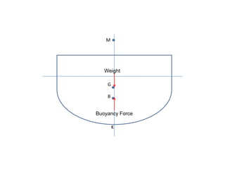
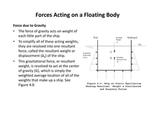
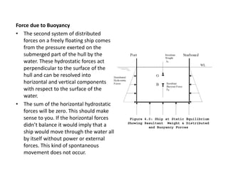
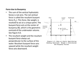
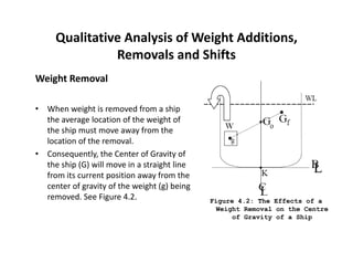
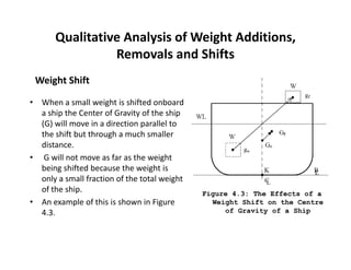
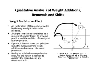
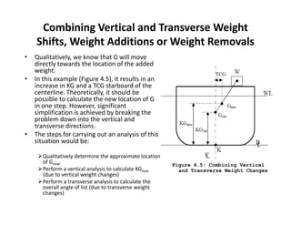
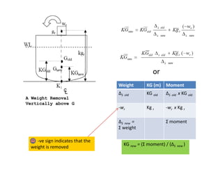
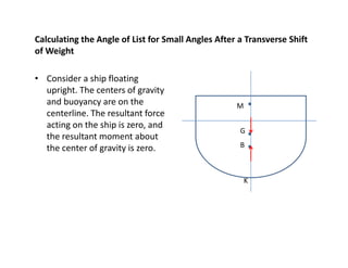
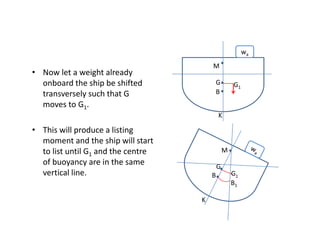
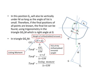

1) The document discusses the forces acting on a floating ship, including the resultant weight force and buoyancy force. 2) It explains how changes in weight distribution on a ship, such as additions, removals, or shifts of weight, can cause the center of gravity to move. 3) The document provides equations to calculate the new vertical location of the center of gravity (KG) after weight changes by taking weighted averages or moments of the weight distribution.


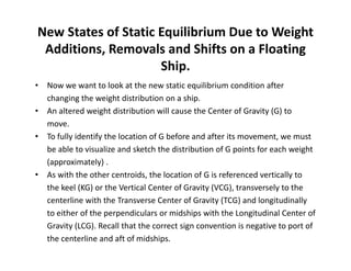
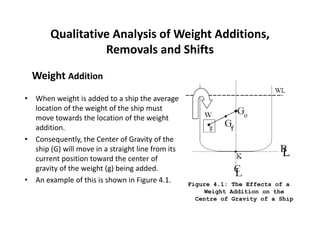
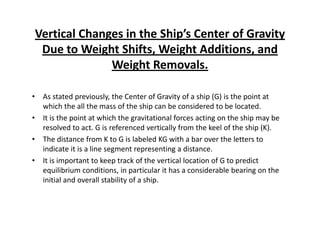
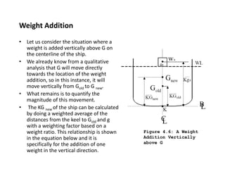
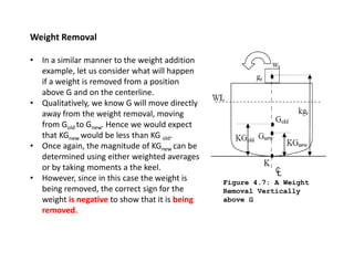
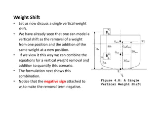
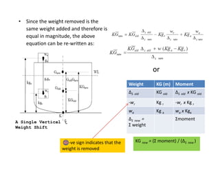
![[7] trim](https://cdn.slidesharecdn.com/ss_thumbnails/7trim-120403043947-phpapp02-thumbnail.jpg?width=640&height=640&fit=bounds)


