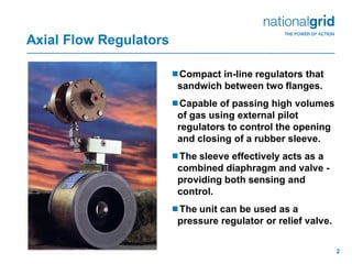
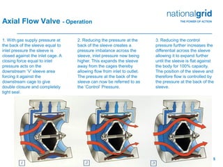
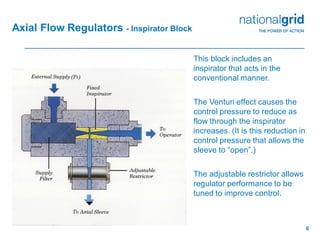
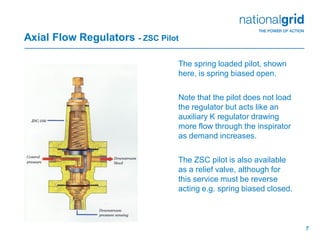
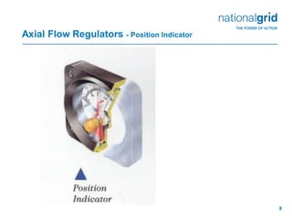
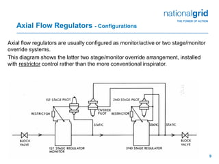
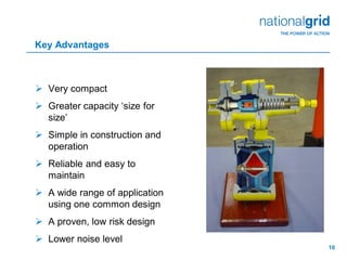
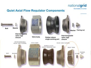
Place your chosen
image here. The four
corners must just
cover the arrow tips.
For covers, the three
pictures should be the
same size and in a
straight line.
Axial Flow Regulators
2
Axial Flow Regulators
Compact in-line regulators that
sandwich between two flanges.
Capable of passing high volumes
of gas using external pilot
regulators to control the opening
and closing of a rubber sleeve.
The sleeve effectively acts as a
combined diaphragm and valve -
providing both sensing and
control.
The unit can be used as a
pressure regulator or relief valve.
3
Axial Flow Regulators - Main Components
This diagram shows an
assembly of:
• Axial Flow Valve
• Inspirator Block &
• ZSC 100 Pilot
The following slides look at
these three items in turn.
An alternative Restrictor
Block is also available for
specialist industrial
applications where fast
response is required.
4
Axial Flow Valve - Sub Components
The main regulator comprises a very simple set of components.
Upstream and downstream cages are interchangeable. This symmetry has the
result that the axial flow valve will control in both directions, although strictly the
fairing nut should be at the downstream side for flow smoothing.
5
1. With gas supply pressure at
the back of the sleeve equal to
inlet pressure the sleeve is
closed against the inlet cage. A
closing force equal to inlet
pressure acts on the
downstream ‘V’ sleeve area
forcing it against the
downstream cage to give
double closure and completely
tight seal.
2. Reducing the pressure at the
back of the sleeve creates a
pressure imbalance across the
sleeve, inlet pressure now being
higher. This expands the sleeve
away from the cages thereby
allowing flow from inlet to outlet.
The pressure at the back of the
sleeve can now be referred to as
the ‘Control’ Pressure.
3. Reducing the control
pressure further increases the
differential across the sleeve
allowing it to expand further
until the sleeve is flat against
the body for 100% capacity.
The position of the sleeve and
therefore flow is controlled by
the pressure at the back of the
sleeve.
Axial Flow Valve - Operation
6
Axial Flow Regulators - Inspirator Block
This block includes an
inspirator that acts in the
conventional manner.
The Venturi effect causes the
control pressure to reduce as
flow through the inspirator
increases. (It is this reduction in
control pressure that allows the
sleeve to “open”.)
The adjustable restrictor allows
regulator performance to be
tuned to improve control.
7
Axial Flow Regulators - ZSC Pilot
The spring loaded pilot, shown
here, is spring biased open.
Note that the pilot does not load
the regulator but acts like an
auxiliary K regulator drawing
more flow through the inspirator
as demand increases.
The ZSC pilot is also available
as a relief valve, although for
this service must be reverse
acting e.g. spring biased closed.
8
Axial Flow Regulators - Position Indicator
9
Axial Flow Regulators - Configurations
Axial flow regulators are usually configured as monitor/active or two stage/monitor
override systems.
This diagram shows the latter two stage/monitor override arrangement, installed
with restrictor control rather than the more conventional inspirator.
10
Key Advantages
 Very compact
 Greater capacity ‘size for
size’
 Simple in construction and
operation
 Reliable and easy to
maintain
 A wide range of application
using one common design
 A proven, low risk design
 Lower noise level
11
Versatility
 Pressure reduction from 100 bar down to 30 mbar
 Active or monitor mode
 Two stage pressure cut
 Volumetric flow control
 Over and under pressure shut off
 Back pressure/relief valve
 Pulsating dampening
 Remote control via pneumatic or electronic signal
 Can be installed in any position
 Low operating differential
12
P1
P1
Falling
Outlet
Pressure
13
Quiet Axial Flow Regulator Components
Bolt Washer
Interchangeable
valve cage
closure Valve body Rubber sleeve
single working part
Interchangeable
valve cage
closure
Washer Fairing nut
14
Pilots and Control Blocks
Restrictor Blocks
Inspirator Blocks
ZSC100 Pilot
1203EP Pilot
15
Control Systems Differences
F F
P1 P2 P1 P2
PilotPilot
Inspirator
control
Restrictor
control
Restrictor

Axial regulator overview

  • 1.
    Place your chosen imagehere. The four corners must just cover the arrow tips. For covers, the three pictures should be the same size and in a straight line. Axial Flow Regulators
  • 2.
    2 Axial Flow Regulators Compactin-line regulators that sandwich between two flanges. Capable of passing high volumes of gas using external pilot regulators to control the opening and closing of a rubber sleeve. The sleeve effectively acts as a combined diaphragm and valve - providing both sensing and control. The unit can be used as a pressure regulator or relief valve.
  • 3.
    3 Axial Flow Regulators- Main Components This diagram shows an assembly of: • Axial Flow Valve • Inspirator Block & • ZSC 100 Pilot The following slides look at these three items in turn. An alternative Restrictor Block is also available for specialist industrial applications where fast response is required.
  • 4.
    4 Axial Flow Valve- Sub Components The main regulator comprises a very simple set of components. Upstream and downstream cages are interchangeable. This symmetry has the result that the axial flow valve will control in both directions, although strictly the fairing nut should be at the downstream side for flow smoothing.
  • 5.
    5 1. With gassupply pressure at the back of the sleeve equal to inlet pressure the sleeve is closed against the inlet cage. A closing force equal to inlet pressure acts on the downstream ‘V’ sleeve area forcing it against the downstream cage to give double closure and completely tight seal. 2. Reducing the pressure at the back of the sleeve creates a pressure imbalance across the sleeve, inlet pressure now being higher. This expands the sleeve away from the cages thereby allowing flow from inlet to outlet. The pressure at the back of the sleeve can now be referred to as the ‘Control’ Pressure. 3. Reducing the control pressure further increases the differential across the sleeve allowing it to expand further until the sleeve is flat against the body for 100% capacity. The position of the sleeve and therefore flow is controlled by the pressure at the back of the sleeve. Axial Flow Valve - Operation
  • 6.
    6 Axial Flow Regulators- Inspirator Block This block includes an inspirator that acts in the conventional manner. The Venturi effect causes the control pressure to reduce as flow through the inspirator increases. (It is this reduction in control pressure that allows the sleeve to “open”.) The adjustable restrictor allows regulator performance to be tuned to improve control.
  • 7.
    7 Axial Flow Regulators- ZSC Pilot The spring loaded pilot, shown here, is spring biased open. Note that the pilot does not load the regulator but acts like an auxiliary K regulator drawing more flow through the inspirator as demand increases. The ZSC pilot is also available as a relief valve, although for this service must be reverse acting e.g. spring biased closed.
  • 8.
    8 Axial Flow Regulators- Position Indicator
  • 9.
    9 Axial Flow Regulators- Configurations Axial flow regulators are usually configured as monitor/active or two stage/monitor override systems. This diagram shows the latter two stage/monitor override arrangement, installed with restrictor control rather than the more conventional inspirator.
  • 10.
    10 Key Advantages  Verycompact  Greater capacity ‘size for size’  Simple in construction and operation  Reliable and easy to maintain  A wide range of application using one common design  A proven, low risk design  Lower noise level
  • 11.
    11 Versatility  Pressure reductionfrom 100 bar down to 30 mbar  Active or monitor mode  Two stage pressure cut  Volumetric flow control  Over and under pressure shut off  Back pressure/relief valve  Pulsating dampening  Remote control via pneumatic or electronic signal  Can be installed in any position  Low operating differential
  • 12.
  • 13.
    13 Quiet Axial FlowRegulator Components Bolt Washer Interchangeable valve cage closure Valve body Rubber sleeve single working part Interchangeable valve cage closure Washer Fairing nut
  • 14.
    14 Pilots and ControlBlocks Restrictor Blocks Inspirator Blocks ZSC100 Pilot 1203EP Pilot
  • 15.
    15 Control Systems Differences FF P1 P2 P1 P2 PilotPilot Inspirator control Restrictor control Restrictor