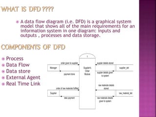
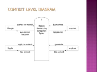
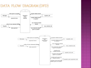
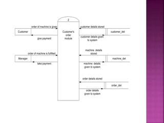
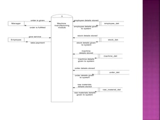
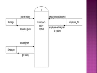
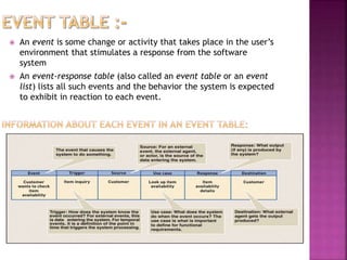
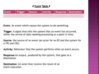
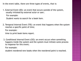
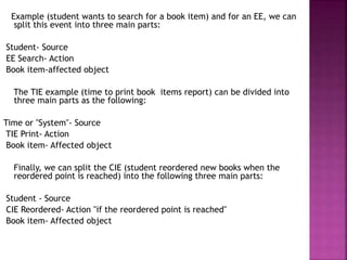
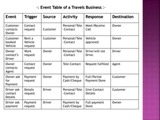
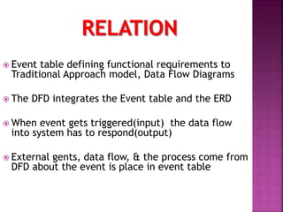
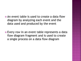
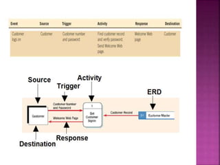
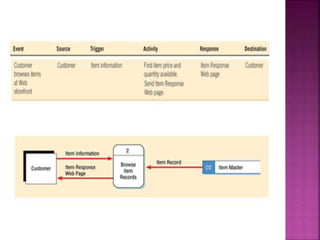
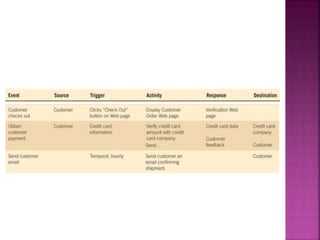
08. Ankita
14. Ashutosh
18. Samiksha
19. Laksh
 A data flow diagram (i.e. DFD) is a graphical system
model that shows all of the main requirements for an
information system in one diagram: inputs and
outputs , processes and data storage.
 Process
 Data Flow
 Data store
 External Agent
 Real Time Link
 Processes should be named and numbered for easy
references.
 The direction of flow is from top to bottom and left to right.
 When a process is exploded into lower level details they are
numbered PHYSICAL and LOGICAL DFDs.
 Readable
 Internally Consistent
 Accurately represents system requirements.
 Minimizing complexity
1. 7+-2 (Miller’s number)
2. Interface minimization
 Data flow consistency
A data dictionary is a structured repository of data about data.
The three classes of items to be defined in data
dictionary are as follows:
 Data Element:
The smallest unit of data that provides for no further
decomposition.
 Data Structure:
A group of data elements handled as a unit.
 Data Flow & Data Store:
Data flows are data structures in motion, whereas data stores
are data structures at rest.
 An event is some change or activity that takes place in the user’s
environment that stimulates a response from the software
system
 An event-response table (also called an event table or an event
list) lists all such events and the behavior the system is expected
to exhibit in reaction to each event.
# Event Table #
Event: An event which causes the system to do something.
Trigger: A signal that tells the system that an event has occurred,
either the arrival of data needing processing or a point in time.
Source: the source of an event (an actor for an EE and the system for
a TIE and CIE).
Activity: Behaviour that the system performs when an event occurs.
Response:An output, produced by the system, that goes to a
destination
Destination: An actor that receive the result of an
event execution
Event Trigger Source Activity Response Destination
In the event table, there are three types of events, that is:
1. External Event (EE): an event that occurs outside of the system,
usually initiated by external actor or user;
For example:
Student wants to search for a book item.
2. Temporal Internal Event (TIE): an event that happens when the system
reaches a specific point of time;
For example:
time to print book items report.
3. Conditional Internal Event (CIE): an event occurs when something
happens inside the system and the system must initiate some process
to response for this event;
For example:
student reordered new books when the reordered point is reached.
Example (student wants to search for a book item) and for an EE, we can
split this event into three main parts:
Student- Source
EE Search- Action
Book item-affected object
The TIE example (time to print book items report) can be divided into
three main parts as the following:
Time or "System"- Source
TIE Print- Action
Book item- Affected object
Finally, we can split the CIE (student reordered new books when the
reordered point is reached) into the following three main parts:
Student - Source
CIE Reordered- Action "if the reordered point is reached"
Book item- Affected object
Event Trigger Source Activity Response Destination
Customer
contacts
Owner
Contact
request Customer
Personal/Tele
-Contact
Meet/Receive
Call
Owner
Customer
booked
Vehicle
Rent a
Vehicle
request
Customer Personal/Tele
-Contact
Vehicle
approved
Owner
Owner
contact’s
Driver
Work
request
Owner Personal/Tele
-Contact
Drive/will not
Drive.
Driver
Owner
contacts
Agent
Contact
request
Owner Tele-Contact Request fulfilled Agent
Owner ask
for
Payment
Payment
request
Owner Payment by
Cash/Cheque
Full/Partial
Payment Done
Customer
Driver ask
contact
Details
Details
request
Driver Personal/Tele
-Contact
Give Contact
Details
Customer
Driver ask
payment
Payment
request
Driver Payment by
Cash/Cheque
Full payment
Done
Owner
-: Event Table of a Travels Business :-
 Event table defining functional requirements to
Traditional Approach model, Data Flow Diagrams
 The DFD integrates the Event table and the ERD
 When event gets triggered(input) the data flow
into system has to respond(output)
 External gents, data flow, & the process come from
DFD about the event is place in event table
 An event table is used to create a data flow
diagram by analyzing each event and the
data used and produced by the event
 Every row in an event table represents a data
flow diagram fragment and is used to create
a single process on a data flow diagram
Co relation between dfd & event table

Co relation between dfd & event table

  • 1.
    08. Ankita 14. Ashutosh 18.Samiksha 19. Laksh
  • 2.
     A dataflow diagram (i.e. DFD) is a graphical system model that shows all of the main requirements for an information system in one diagram: inputs and outputs , processes and data storage.  Process  Data Flow  Data store  External Agent  Real Time Link
  • 3.
     Processes shouldbe named and numbered for easy references.  The direction of flow is from top to bottom and left to right.  When a process is exploded into lower level details they are numbered PHYSICAL and LOGICAL DFDs.  Readable  Internally Consistent  Accurately represents system requirements.  Minimizing complexity 1. 7+-2 (Miller’s number) 2. Interface minimization  Data flow consistency
  • 4.
    A data dictionaryis a structured repository of data about data. The three classes of items to be defined in data dictionary are as follows:  Data Element: The smallest unit of data that provides for no further decomposition.  Data Structure: A group of data elements handled as a unit.  Data Flow & Data Store: Data flows are data structures in motion, whereas data stores are data structures at rest.
  • 11.
     An eventis some change or activity that takes place in the user’s environment that stimulates a response from the software system  An event-response table (also called an event table or an event list) lists all such events and the behavior the system is expected to exhibit in reaction to each event.
  • 12.
    # Event Table# Event: An event which causes the system to do something. Trigger: A signal that tells the system that an event has occurred, either the arrival of data needing processing or a point in time. Source: the source of an event (an actor for an EE and the system for a TIE and CIE). Activity: Behaviour that the system performs when an event occurs. Response:An output, produced by the system, that goes to a destination Destination: An actor that receive the result of an event execution Event Trigger Source Activity Response Destination
  • 13.
    In the eventtable, there are three types of events, that is: 1. External Event (EE): an event that occurs outside of the system, usually initiated by external actor or user; For example: Student wants to search for a book item. 2. Temporal Internal Event (TIE): an event that happens when the system reaches a specific point of time; For example: time to print book items report. 3. Conditional Internal Event (CIE): an event occurs when something happens inside the system and the system must initiate some process to response for this event; For example: student reordered new books when the reordered point is reached.
  • 14.
    Example (student wantsto search for a book item) and for an EE, we can split this event into three main parts: Student- Source EE Search- Action Book item-affected object The TIE example (time to print book items report) can be divided into three main parts as the following: Time or "System"- Source TIE Print- Action Book item- Affected object Finally, we can split the CIE (student reordered new books when the reordered point is reached) into the following three main parts: Student - Source CIE Reordered- Action "if the reordered point is reached" Book item- Affected object
  • 15.
    Event Trigger SourceActivity Response Destination Customer contacts Owner Contact request Customer Personal/Tele -Contact Meet/Receive Call Owner Customer booked Vehicle Rent a Vehicle request Customer Personal/Tele -Contact Vehicle approved Owner Owner contact’s Driver Work request Owner Personal/Tele -Contact Drive/will not Drive. Driver Owner contacts Agent Contact request Owner Tele-Contact Request fulfilled Agent Owner ask for Payment Payment request Owner Payment by Cash/Cheque Full/Partial Payment Done Customer Driver ask contact Details Details request Driver Personal/Tele -Contact Give Contact Details Customer Driver ask payment Payment request Driver Payment by Cash/Cheque Full payment Done Owner -: Event Table of a Travels Business :-
  • 16.
     Event tabledefining functional requirements to Traditional Approach model, Data Flow Diagrams  The DFD integrates the Event table and the ERD  When event gets triggered(input) the data flow into system has to respond(output)  External gents, data flow, & the process come from DFD about the event is place in event table
  • 17.
     An eventtable is used to create a data flow diagram by analyzing each event and the data used and produced by the event  Every row in an event table represents a data flow diagram fragment and is used to create a single process on a data flow diagram