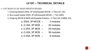
1. 110V MAIN LV DC MAIN SWITCH BOARD
1. Incoming feeders 400A, 3P withdrawable MCCB – 2 Tiers (A1, B1)
2. Bus coupler feeder 400A, 3P withdrawable MCCB – 1 Tier (AB0)
3. Outgoing MCCB & MCB withdrawable Feeders – 4 Tiers (A2, A3&B2, B3)
a. 250A, 3P MCCB – 3 modules
b. C-16A, 3P MCB – 30 modules
c. C-25A, 3P MCB – 29 modules
d. C-32A, 3P MCB – 38 modules
e. C-40A, 3P MCB – 8 modules
2. 2
DB PANEL - SDB-LH1
1. Incoming breaker 160A, 4P withdrawable MCCB
2. Outgoing MCB
a. C-16A, 1P MCB – 16 qty.
b. C-25A, 1P MCB – 7 qtys.
c. C-16A, 3P MCB – 10 qtys.
d. C-32A, 3P MCB – 9 qtys.
3. 3
Rated Nominal Voltage : 110V DC
Rated Current : 400A
Fault Level : 50kA for 1 Sec.
Degree of Protection Switchboard : IP 43
Form of Segregation : Form 4B Type-6
Cable Entry – Incoming Side : Bottom
Outgoing Side : Bottom
Cable Access
a) Incoming : Rear
b) Outgoing : Rear
Type of Mounting : Floor Mounting
Control Supply Voltage : 110V DC - indication lamps (Internally derived)
240V AC – Heater Circuit & Lamp (Externally
derived)
Main Busbar (Tinned Copper) : R/Y/B Phase – 1x60x10 Cu per phase
Neutral – 1x60x10 Cu
Earth – 1x300x10 Cu
4. 4
Rated Nominal Voltage : 415 V AC 3Ph / 240V AC 1Ph
System Frequency : 50 Hz
Rated Current : 160A
Fault Level : 25kA for 1 Sec.
Degree of Protection Switchboard : IP 54
Form of Segregation : Form 2B
Cable Entry – Incoming Side : Top/Bottom
Outgoing Side : Top
Cable Access
a) Incoming : Front
b) Outgoing : Front
Type of Mounting : Wall/Floor Mounting
Control Supply Voltage : 415V AC – Power Circuit
240V AC – Control Circuit (internally derived)
12. LV DC – MCCB FEATURES
Thermal magnetic
Thermal Adj 63% to 100%
Magnetic Adj
Electronic
40% to 100%
Pre set curves to choose
6
8
12
10
0.8
0.63
1
Ir (x ln) Ii (x ln)
125A
TRIPPED
ON OFF
MANUAL OPERATION
17. 17
LV DC – MCB MAIN FEATURES
MCB Functions
Protection against
overloads and short-
circuits
Switching and isolation
OPERATION DIRECTION
ON
(O)
OFF
(I)
21. 21
DB – MAIN FEATURES
MANUAL CHANGE OVER SWITCH OPERATING PRNCIPLE
DOOR HANDLE OPERATION
22. 22
INDICATION LIGHTS, PUSH BUTTON & SELECTOR SWITCHES – LV DC
LV DC & DB – MAIN FEATURES
If line side (Incoming Supply) is energized, +VE phase lamps will work
Supply Healthy – RED
Analogue Voltmeter, Ammeter
Based on the MCCB & MCB position the following lamp identification will work
RED – MCCB Close
GREEN – MCCB Open
AMBER – TRIP position for MCCB & MCB
BLACK P.B. – Lamp Test
Selector Switch
Bus Coupler auto Off/On
If line side (Incoming Supply Source-1 or Source-2) is energized, R/Y/B phases individual lamps will work
R-phase – RED / Y-phase – YELLOW / B-phase – BLUE
RED – HEATER On
Analogue Voltmeter, Ammeter with selector switches
Selector Switch
Heater selector Off/On
INDICATION LIGHTS, PUSH BUTTON & SELECTOR SWITCHES – DB