![Valve model Type of actuation Port size
1 Ǟ 4/2 (P Ǟ A/B)
Flow characteristics Note 2)
b
0.36 0.12 0.46 0.35 0.120.46
0.33 0.12 0.47 0.31 0.120.47
0.39 0.10
0.59
[0.40]
0.43
[0.33]
0.16
[0.11]
0.36
0.42
[0.33]
0.16
[0.080]
0.46 0.32 0.11
0.58
[0.32]
Cv
C [dm3
/
(s• bar)]
b Cv
C [dm3
/
(s• bar)]
4/2 Ǟ 5/3 (A/B Ǟ EA/EB)
Single
Double
Closed
center
Exhaust
center
Pressure
center
Single
Double
Closed
center
Exhaust
center
Pressure
center
Single
Double
Closed
center
Exhaust
center
Pressure
center
M3 x 0.5
Effective
area
mm2
0.9
—M5 x 0.8
—
Weight (g)
22
25
28
48 (22)
51 (25)
54 (28)
22
25
28
Flow Characteristics/Weight
With Bracket
Air operated
valve type
The mounting bracket for the 2 position
double solenoid and 3 position is supplied
unattached.
SYJA3„20-M3-F
Fluid
Specifications
Operating pressure
range
MPa
Ambient and fluid temperature °C
Lubrication
Mounting orientation
Impact/Vibration resistance (m/s2
)
2 position single
2 position double
3 position
2 position single
2 position double
3 position
Air
0.15 to 0.7
0.1 to 0.7
0.2 to 0.7
Operating pressure to 0.7
0.1 to 0.7
0.2 to 0.7
–10 to 50 (No freezing. Refer to page 5-11-4.)
Not required
Unrestricted
300/50
M3 x 0.5
M3 x 0.5
M3 x 0.5
Pilot
port size
Pilot Pressure Range (Single pilot)
0.6
0.5
0.4
0.3
0.2
0.1 0.2 0.3 0.4 0.5 0.6
Operating pressure range MPa
PilotpressureMPa
Pilot pressure range
MPa
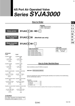
Body ported
Bodyported
5portbasemounted
(withsub-plate)
4Portbasemounted
(Formanifold)Note1)
Note 2)
Base mounted
2 position
3 position
2 position
3 position
2 position
3 position
Grommet
SYJA3„20-M3
SYJA3„40-M5
SYJA3„30
∗ Refer to memo for contents that have been changed.
Note 1)
Note 1) In the case of single type, be certain that pressure within operating pressure range be supplied
to supply port, because return pressure is introduced from supply port {1(P)} for activation.
Note 2) Impact resistance: No malfunction resulted from the impact test using a drop impact tester.
The test was performed on the axis and right angle directions of the
main valve, when pilot signal is ON and OFF. (Value in the initial state)
Vibration resistance: No malfunction occurred in one sweep test between 45 and 2000 Hz.
Test was performed to axis and right angle directions of the main valve
when pilot signal is ON and OFF. (Value in the initial state)
Note 3)
Pilot pressure
range
Note 1) Value when used on a manifold. Refer to page 5-2-19 for
details.
Note 2) [ ]: Denotes normal position.
Note 3) ( ): Without sub-plate.
Note 4) 5 port base mounted without sub-plate: SYJA3„40
Series SYJA3000
5-2-20
2](data:image/gif;base64,R0lGODlhAQABAIAAAAAAAP///yH5BAEAAAAALAAAAAABAAEAAAIBRAA7)
Recommended
More Related Content
What's hot
What's hot (19)
Viewers also liked
Viewers also liked (16)
Similar to Syja3000
Similar to Syja3000 (20)
More from kongurpkp
More from kongurpkp (20)
Recently uploaded
Recently uploaded (20)
Syja3000
- 1. S„A V„A S„A V„A VM VR VH VHS How to Order Manifold Base 2 position single 2 position double 2 position single 2 position double 3 position closed center 3 position exhaust center 3 position pressure center 3 position pressure center 3 position exhaust center 3 position closed center JIS Symbol 5 port 4 port (B) 2 1 (P) 3 (R) 5 (R) 1 (P) 3 (R) (A) 4 (B) 2 1 (P) 3 (R) 5 (R) (A) 4 (B) 2 1 (P) 3 (R) 5 (R) (A) 4 (B) 2 1 (P) 3 (R) 5 (R) (A) 4 (B) 2 1 (P) 3 (R) 5 (R) (A) 4 (B) 2 (A) 4 1 (P) 3 (R) (B) 2 (A) 4 1 (P) 3 (R) (B) 2 (A) 4 1 (P) 3 (R) (B) 2 (A) 4 1 (P) 3 (R) (B) 2 (A) 4 Caution 3 position closed center 4 3 2 position double 2 position single 2 1 3 position exhaust center 5 3 position pressure center Type of actuation SYJA3 201 (Manifold use only)SYJA3 302 SYJA3 402 Without sub-plate Port size M5 port with sub-plate M5 Nil M3 Same manifolds as series SYJ3000 are prepared. SS5YJA3 Fill the same as SS5YJ3 (Example) SS5YJA3-41-03-M5 1 pc. ∗SYJA3140 1 pc. ∗SYJA3240 1 pc. ∗SYJ3000-21-2A 1 pc. How to Order The asterisk denotes the symbol for assembly. Prefix it to the part nos. of the solenoid valve, etc. Without bracket With bracketF Nil Bracket Instruct by specifying the valves and blanking plate assembly to be mounted on the manifold along with the manifold base model no. ········ ······························ ······························ ···················· For Safety Instructions and Solenoid Valve Precautions, refer to pages 5-11-2 to 6. 4/5 Port Air Operated Valve Series SYJA3000 Body ported Base mounted (4 port) Base mounted (5 port) 5-2-19 1
- 2. Valve model Type of actuation Port size 1 Ǟ 4/2 (P Ǟ A/B) Flow characteristics Note 2) b 0.36 0.12 0.46 0.35 0.120.46 0.33 0.12 0.47 0.31 0.120.47 0.39 0.10 0.59 [0.40] 0.43 [0.33] 0.16 [0.11] 0.36 0.42 [0.33] 0.16 [0.080] 0.46 0.32 0.11 0.58 [0.32] Cv C [dm3 / (s• bar)] b Cv C [dm3 / (s• bar)] 4/2 Ǟ 5/3 (A/B Ǟ EA/EB) Single Double Closed center Exhaust center Pressure center Single Double Closed center Exhaust center Pressure center Single Double Closed center Exhaust center Pressure center M3 x 0.5 Effective area mm2 0.9 —M5 x 0.8 — Weight (g) 22 25 28 48 (22) 51 (25) 54 (28) 22 25 28 Flow Characteristics/Weight With Bracket Air operated valve type The mounting bracket for the 2 position double solenoid and 3 position is supplied unattached. SYJA3„20-M3-F Fluid Specifications Operating pressure range MPa Ambient and fluid temperature °C Lubrication Mounting orientation Impact/Vibration resistance (m/s2 ) 2 position single 2 position double 3 position 2 position single 2 position double 3 position Air 0.15 to 0.7 0.1 to 0.7 0.2 to 0.7 Operating pressure to 0.7 0.1 to 0.7 0.2 to 0.7 –10 to 50 (No freezing. Refer to page 5-11-4.) Not required Unrestricted 300/50 M3 x 0.5 M3 x 0.5 M3 x 0.5 Pilot port size Pilot Pressure Range (Single pilot) 0.6 0.5 0.4 0.3 0.2 0.1 0.2 0.3 0.4 0.5 0.6 Operating pressure range MPa PilotpressureMPa Pilot pressure range MPa Body ported Bodyported 5portbasemounted (withsub-plate) 4Portbasemounted (Formanifold)Note1) Note 2) Base mounted 2 position 3 position 2 position 3 position 2 position 3 position Grommet SYJA3„20-M3 SYJA3„40-M5 SYJA3„30 ∗ Refer to memo for contents that have been changed. Note 1) Note 1) In the case of single type, be certain that pressure within operating pressure range be supplied to supply port, because return pressure is introduced from supply port {1(P)} for activation. Note 2) Impact resistance: No malfunction resulted from the impact test using a drop impact tester. The test was performed on the axis and right angle directions of the main valve, when pilot signal is ON and OFF. (Value in the initial state) Vibration resistance: No malfunction occurred in one sweep test between 45 and 2000 Hz. Test was performed to axis and right angle directions of the main valve when pilot signal is ON and OFF. (Value in the initial state) Note 3) Pilot pressure range Note 1) Value when used on a manifold. Refer to page 5-2-19 for details. Note 2) [ ]: Denotes normal position. Note 3) ( ): Without sub-plate. Note 4) 5 port base mounted without sub-plate: SYJA3„40 Series SYJA3000 5-2-20 2
- 3. S„A V„A S„A V„A VM VR VH VHS 2 position single: SYJA3120-M3(-F) Dimesions: Body Ported 2 position single: SYJA3140-M5 Dimensions: Base Mounted 2 position double: SYJA3220-M3(-F) 2 position double: SYJA3240-M5 3 position closed center/exhaust center/pressure center SYJA3 20-M3(-F) 3 position closed center/exhaust center/pressure center SYJA3 40-M5 A A B B PRR R P R A B PR R A AB B A AB B A AB B 10 (28.4) (22) 22 4 33 36 28.5 21 13 10 (10) 77 15 15 10 7 7 7 19 49 54.5 21.6 15 13.5 (18.5) (21) (18.5) 7.1 (11)(0.5) 10 7 7 (11)(0.5) 1.8 (21) (18.5) 13.5 7(13.5) 1.5 4 8.2 15 36 (18.5) 41.6 7.1 7 8.2 11 10 36(2) (16.4) (35) 11 17.5 22 36 14 41.6 111.5 2.5 17.5 21 10 10 10 9 14 14 15 1010 52.555 1.51.5 1.5 4 8.2 1.5 4 1.5 1.8 22 3 54.5 16 18.9 33 1.5 2.5 11 13 21 28.5 17.5 1.5 (For mounting) M3 x 0.5 (Pilot port)M3 x 0.5 (Pilot port) 2-M3 x 0.5 (Pilot port) 2-M3 x 0.5 (Pilot port) 2-M3 x 0.5 (Pilot port) 2-M3 x 0.5 (Pilot port) M5 x 0.8 (Piping port) M3 x 0.5 (Piping port) 2-ø3.2 (For mounting) 2-ø3.5 (For mounting) 2-ø3.2 (For manifold mounting) 2-ø1.8 (For mounting) 2-ø3.2 equivalent (For mounting) 2-ø3.2 equivalent (For mounting) 2-ø3.2 ø1 (Bleed port) ø1 (Bleed port) (Bracket) R2 P R1 14 28 1010 5 R2 P P1 28.5 13 28 1010 910 10 5 5 M5 x 0.8 (Piping port) M3 x 0.5 (Piping port) (Piping port) 2-ø1 (Bleed port) 2-ø1 (Bleed port) M3 x 0.5 2-ø1 (Bleed port) M5 x 0.8 (Piping port) 2-ø1 (Bleed port) R2 P R1 3 4 5 3 4 5 Manual override Manual override Manual override Manual override Manual override Manual override 5-2-21 Series SYJA30004/5 Port Air Operated Valve 3
- 4. (Example) SS5YJA5-42-03-01 1 set ∗ SYJA5140 1 set ∗ SYJA5240 1 set ∗ SYJ5000-21-1A 1 set How to Order Manifold Base 3 position closed center 4 3 2 position double 2 position single 2 1 3 position exhaust center 5 3 position pressure center Type of actuation One-touch fitting for ø6C6 One-touch fitting for ø4 M5 x 0.8 C4 M5 A, B port size SYJA5 201 SYJA5 402 Without sub-plate Port size 1/8 With sub-plate 01 Nil Rc G NPT NPTF Thread type F N T Nil M5 How to Order 2 position double 3 position exhaust center 2 position single 3 position closed center 3 position pressure center JIS Symbol Body ported 2 position double 3 position exhaust center 2 position single 3 position closed center 3 position pressure center Base mounted (B) 2 1 (P) 5 (R1) 3 (R2) 1 (P) 5 (R1) 3 (R2) (A) 4 (B) 2 1 (P) 5 (R1) 3 (R2) (A) 4 (B) 2 1 (P) 5 (R1) 3 (R2) (A) 4 (B) 2 1 (P) 3 (R) (A) 4 (B) 2 1 (P) 3 (R) (A) 4 (B) 2 1 (P) 3 (R) (A) 4 (B) 2 1 (P) 3 (R) (A) 4 (B) 2 1 (P) 3 (R) (A) 4 (B) 2 1 (P) 5 (R1) 3 (R2) (A) 4 (B) 2 (A) 4 Caution Same manifolds as series SYJ5000 are prepared. SS5YJA5 Fill the same as SS5YJ5. The asterisk denotes the symbol for assembly. Prefix it to the part nos. of the solenoid valve, etc. Without bracket With bracketF Nil Bracket Instruct by specifying the valves and blanking plate assembly to be mounted on the manifold along with the manifold base model no. ············ ····························· ····························· ··················· For Safety Instructions and Solenoid Valve Precautions, refer to pages 5-11-2 to 5-11-6. 4/5 Port Air Operated Valve Series SYJA5000 Body ported Base mounted 5-2-22 4
- 5. S„A V„A S„A V„A VM VR VH VHS Valve model Type of actuation Port size 1 Ǟ 4/2 (P Ǟ A/B) Flow characteristics Note 1) b Cv C [dm3 / (s·bar)] b Cv C [dm3 / (s·bar)] 0.41 0.130.47 0.41 0.130.47 0.44 0.130.49 0.40 0.120.44 0.37 0.120.46 0.43 [0.35] 0.13 [0.10] 0.47 [0.39] 0.51 [0.38] 0.14 [0.10] 0.49 [0.39] 0.42 0.120.45 0.39 0.180.69 0.39 0.120.44 0.40 0.190.69 0.40 0.120.43 0.40 0.150.56 0.37 [0.37] 0.10 [0.11] 0.41 [0.41] 0.40 [0.37] 0.15 [0.10] 0.57 [0.41] 0.37 0.100.41 0.36 0.190.70 0.40 0.120.47 0.37 0.190.72 0.34 0.120.44 0.54 0.190.67 0.38 [0.38] 0.11 [0.11] 0.41 [0.41] 0.41 [0.39] 0.23 [0.12] 0.82 [0.44] 0.36 0.110.41 0.21 0.190.79 0.32 0.210.83 0.28 0.180.80 0.34 0.200.86 0.26 0.180.71 0.24 [0.44] 0.26 [0.18] 1.1 [0.60] 0.29 [0.38] 0.24 [0.12] 0.99 [0.47] 0.38 0.180.72 4/2 Ǟ 5/3 (A/B Ǟ EA/EB) Single Double Closed center Exhaust center Pressure center Single Double Closed center Exhaust center Pressure center Single Double Closed center Exhaust center Pressure center Single Double Closed center Exhaust center Pressure center M5 x 0.8 1/8 A, B port: C4 (One-touch fitting for ø4) P, R port: M5 x 0.8 A, B port: C6 (One-touch fitting for ø6) P, R port: M5 x 0.8 Weight (g) 45 60 70 52 67 77 52 67 77 Flow Characteristics/Weight With Bracket Air operated valve type The mounting bracket is supplied unattached. SYJA5120-M5-F M5 x 0.8 Pilot port size Bodyported 2 position 3 position 2 position 3 position 2 position 3 position SYJA5„20-M5 SYJA5„20-C4 SYJA5„20-C6 79 (45) 94 (60) 104(70) M5 x 0.8 Basemounted (withsub-plate) 2 position 3 position SYJA5„40-01 0.6 0.5 0.4 0.3 0.1 0.2 0.2 0.3 0.4 0.5 0.6 Operating pressure range MPa PilotpressureMPa Pilot pressure range Pilot Pressure Range (Single pilot) Fluid Specifications Operating pressure range MPa Ambient and fluid temperature °C Lubrication Mounting orientation Impact/Vibration resistance (m/s2 ) 2 position single 2 position double 3 position 2 position single 2 position double 3 position Air 0.15 to 0.7 0.1 to 0.7 0.15 to 0.7 (0.4 x P+0.1) to 0.7 P: Operating pressure 0.1 to 0.7 0.15 to 0.7 –10 to 50 (No freezing. Refer to page 5-11-4.) Not required Unrestricted 300/50 Pilot pressure range MPa Note 2) Body ported Base mounted Note 1) [ ]: Denotes normal position. Note 2) ( ): Without sub-plate. Note 3) 5 port base mounted without sub-plate: SYJA5„40 Note 1) Note 1) In the case of single type, be certain that pressure within operating pressure range be supplied to supply port, because return pressure is introduced from supply port {1(P)} for activation. Note 2) Impact resistance: No malfunction resulted from the impact test using a drop impact tester. The test was performed on the axis and right angle directions of the main valve, when pilot signal is ON and OFF. (Value in the initial state) Vibration resistance: No malfunction occurred in one sweep test between 45 and 2000 Hz. Test was performed to axis and right angle directions of the main valve when pilot signal is ON and OFF. (Value in the initial state) Note 2) 5-2-23 Series SYJA50004/5 Port Air Operated Valve 5
- 6. 2 position single: SYJA5120-M5(-F) Dimesions: Body Ported 2 position single: SYJA5140-01२ Dimensions: Base Mounted 2 position double: SYJA5220-M5 2 position double: SYJA5240-01२ 3 position closed center/exhaust center/pressure center SYJA5 20-M5 3 position closed center/exhaust center/pressure center SYJA5 40-01२ 41.5 M5 x 0.8 (Pilot port) 10 5 11 1 15 2-ø2.6 2-ø3.5 2-ø2.6 (For mounting) (For manifold mounting) 19 23 19.5 21 19 10 (25) 11.5 (37) (30) (18) M5 x 0.8 (Piping port) (46.5) 24.5 20 3 ø1.8 (Bleed port) With fiflter (80 mesh) A B (Bracket) (2.3) 3.5 4 11 R1 R2 P (For mounting) 2-ø2.6 2-M5 x 0.8 (Pilot port) (For manifold mounting) 44 54 11 21 28 23 10 15 11.5 11 21 32 24 15 15 15 17 47 42 24 1 45.5 17 24 32 17 17 45.5 54 1 1 24 47 42 24 32 17 17 45.5 48 17.5 70.5 43 21.5 8.5 6 6 33.5 46.5 46.5 6 6 8.5 33.5 46.5 33.5 21.5 6 6 8.5 21.5 1 1 24 19 37.5 70.5 5 3 1 1 11 20 23 24.5 20 23 24.5 11.5 15 3 11 5 1 2-ø2.6 (For mounting) R1 R2 P B R1 P R2 M5 x 0.8 (Piping port) 2-ø1.8 (Bleed port) 2-M5 x 0.8 M5 x 0.8 (Pilot port) (Piping port) 2-M5 x 0.8 2-M5 x 0.8 (Pilot port) M5 x 0.8 (Pilot port) (For manifold mounting) 2-ø2.6 (Piping port) (For mounting) 2-ø2.6 (For mounting) 2-ø4.3 2-ø1.8 (Bleed port) 2-ø1.8 (Bleed port) 2-ø4.3 (For mounting) 2-ø4.3 1/8 1/8 (Piping port) 1/8 437.5 37.5 37.5 4 2 A AB AB B A B R P A AB B R P R P 4 (Piping port) (Pilot port) (For mounting) 1 ø1.8 (Bleed port) With fiflter (80 mesh) With fiflter (80 mesh) With fiflter (80 mesh) With fiflter (80 mesh) 2-ø1.8 (Bleed port) With fiflter (80 mesh) A A B 3 4 5 3 4 5 Manual override Manual override Manual override Manual override Manual override Manual override Series SYJA5000 5-2-24 6
- 7. S„A V„A S„A V„A VM VR VH VHS 5-2-25 How to Order Manifold Base 3 position closed center 4 3 2 position double 2 position single 2 1 3 position exhaust center 5 3 position pressure center Type of actuation One-touch fitting for ø8C8 One-touch fitting for ø6 1/8 C6 01 A, B port size SYJA7 201 SYJA7 402 Without sub-plate Port size 1/8 With sub-plate 01 1/4 With sub-plate 02 Nil Rc G NPT NPTF Thread type F N T Nil 01 How to Order Same manifolds as series SYJ7000 are prepared. SS5YJA7 Fill the same as SS5YJ7. (Example) SS5YJA7-41-03-01 1 pc. ∗ SYJA7140 1 pc. ∗ SYJA7240 1 pc. ∗ SYJ7000-21-1A 1 pc. The asterisk denotes the symbol for assembly. Prefix it to the part nos. of the solenoid valve, etc. 2 position double 3 position exhaust center 2 position single 3 position closed center 3 position pressure center JIS Symbol Body ported 2 position double 3 position exhaust center 2 position single 3 position closed center 3 position pressure center Base mounted (B) 2 1 (P) 5 (R1) 3 (R2) (A) 4 (B) 2 1 (P) 5 (R1) 3 (R2) (A) 4 (B) 2 1 (P) 5 (R1) 3 (R2) (A) 4 (B) 2 1 (P) 3 (R2) 5 (R1) (A) 4 (B) 2 1 (P) 3 (R2) 5 (R1) (A) 4 (B) 2 1 (P) 3 (R2) 5 (R1) (A) 4 (B) 2 1 (P) 3 (R2) 5 (R1) (A) 4 (B) 2 1 (P) 3 (R2) 5 (R1) (A) 4 (B) 2 1 (P) 5 (R1) 3 (R2) (A) 4 (B) 2 1 (P) 5 (R1) 3 (R2) (A) 4 Caution Without bracket With bracketF Nil Bracket Instruct by specifying the valves and blanking plate assembly to be mounted on the manifold along with the manifold base model no. ········· ···························· ···························· ················· For Safety Instructions and Solenoid Valve Precautions, refer to pages 5-11-2 to 5-11-6. 4/5 Port Air Operated Valve Series SYJA7000 Body ported Base mounted 7
- 8. With Bracket Air operated valve type As a bracket is designed for a body, be sure that a bracket is attached when ordering and operating. SYJA7120-01-F Body ported Base mounted Fluid Specifications Operating pressure range MPa Ambient and fluid temperature °C Lubrication Mounting orientation Impact/Vibration resistance (m/s2 ) 2 position single 2 position double 3 position 2 position single 2 position double 3 position Air 0.15 to 0.7 0.1 to 0.7 0.15 to 0.7 (0.4 x P+0.1) to 0.7 P: Operating pressure 0.1 to 0.7 0.15 to 0.7 –10 to 50 (No freezing. Refer to page 5-11-4.) Not required Unrestricted 300/50 Pilot pressure range MPa Pilot Pressure Range (Single pilot) 0.6 0.5 0.4 0.3 0.1 0.2 0.2 0.3 0.4 0.5 0.6 Pilot pressure range Operating pressure range MPa PilotpressureMPa Note 2) Note 1) Note 1) In the case of single type, be certain that pressure within operating pressure range be supplied to supply port, because return pressure is introduced from supply port {1(P)} for activation. Note 2) Impact resistance: No malfunction resulted from the impact test using a drop impact tester. The test was performed on the axis and right angle directions of the main valve, when pilot signal is ON and OFF. (Value in the initial state) Vibration resistance: No malfunction occurred in one sweep test between 45 and 2000 Hz. Test was performed to axis and right angle directions of the main valve when pilot signal is ON and OFF. (Value in the initial state) Series SYJA7000 5-2-26 8
- 9. S„A V„A S„A V„A VM VR VH VHS Valve model Type of actuation Port size 1 Ǟ 4/2 (P Ǟ A/B) Flow characteristics Note 2) b CvC [dm3 / (s• bar)] b Cv C [dm3 / (s• bar)] 4/2 Ǟ 5/3 (A/B Ǟ EA/EB) Single Double Closed center Exhaust center Pressure center Single Double Closed center Exhaust center Pressure center Single Double Closed center Exhaust center Pressure center Single Double Closed center Exhaust center Pressure center Single Double Closed center Exhaust center Pressure center 1/8 1/8 Note 1) A, B port: C6 (One-touch fitting for ø6) P, R port: 1/8 A, B port: C8 (One-touch fitting for ø8) P, R port: 1/8 Note 3) Weight (g) 90 110 120 101 121 131 101 121 131 170 (90) 190 (110) 200 (120) 170 (90) 190 (110) 200 (120) Flow Characteristics/Weight M5 x 0.8 M5 x 0.8 M5 x 0.8 Pilot port size Bodyported 2 position 3 position 2 position 2 position 2 position 2 position 3 position 3 position 3 position 3 position SYJA7„20-01 SYJA7„20-C6 SYJA7„20-C8 SYJA7„40-01 Note 1) P, A, B Port: Rc1/8 is R1, R2 port: Rc (PT) 1/4 Note 2) [ ]: Denotes normal position Note 3) ( ): Without sub-plate Note 4) 5 port base mounted without sub-plate: SYJA„40 0.36 0.37 0.50 0.37 [0.50] 0.33 0.27 0.37 0.36 [0.40] 0.39 0.35 0.38 0.57 [0.46] 0.45 0.36 0.48 0.43 [0.54] 0.41 0.46 0.45 0.23 [0.55] 0.58 0.45 0.34 0.78 [0.25] 0.4 0.35 0.27 0.45 [0.22] 0.52 0.42 0.33 0.59 [0.25] 0.57 0.48 0.35 0.78 [0.25] 0.61 0.50 0.35 0.84 [0.25] 0.34 0.35 0.35 [0.52] 0.37 0.32 0.33 0.32 [0.54] 0.30 0.34 0.29 0.35 [0.49] 0.39 0.37 0.46 0.36 [0.57] 0.45 0.35 0.44 0.27 [0.56] 0.47 0.63 0.49 0.73 [0.39] 0.45 0.53 0.49 0.61 [0.38] 0.39 0.61 0.49 0.67 [0.38] 0.42 0.71 0.57 0.86 [0.41] 0.56 0.74 0.60 0.87 [0.43] 0.58 2.4 2.0 3.0 [1.3] 1.8 2.2 1.9 2.5 [1.3] 1.6 2.3 2.0 2.6 [1.3] 1.7 2.8 2.1 3.4 [1.3] 2.1 2.9 2.2 3.7 [1.4] 2.1 1/4 Note 1) Basemounted(Withsub-plate) SYJA7„40-02 2.2 1.8 1.2 3.0 [0.83] 1.6 1.4 1.1 1.8 [0.78] 2.0 1.7 1.2 1.9 [0.86] 2.3 1.9 1.2 3.3 [0.85] 2.3 1.9 1.3 3.6 [0.83] 5-2-27 Series SYJA70004/5 Port Air Operated Valve 9
- 10. 2 position single: SYJA7120-01२(-F) Dimesions: Body Ported 2 position single: SYJA7140- २ Dimensions: Base Mounted 2 position double: SYJA7220-01२ 2 position double: SYJA7240- २ 3 position closed center/exhaust center/pressure center SYJA7 20-01२ 3 position closed center/exhaust center/pressure center SYJA7 40- २ M5 x 0.8 M5 x 0.8 2-ø3.2 2-ø4.3 2-ø4.5 (For mounting) (For manifold mounting) (Piping port) (Pilot port) 2-M5 x 0.8 2-M5 x 0.8 (For mounting) 60 68.8 63 31.5 2222 63.3 34 R1PR2 B A 8.5 74.6 63.6 31.5 34 8.5 28.3 A B 35 35 (Pilot port) 2-ø4.3 2-M5 x 0.8 (31.9) 27.2 1 63.6 35 27.2 35 38 18 14 211.6 28 25 29 35 27.2 89 32.545.5 17 13 1 1 3 17 13 3 1 25 29 14 18 28 211.6 35 74.6 (34) (26) 18 18 14 34 27 A B R1PR2 A A B 65.6 (69.2) 13 21 1.6 29 (44) (36) 15 11 1 25.5 40 55 54 20 12 11.5 63 2222 20 12 11.5 3 1 2-ø3.2 2-ø3.2 2-ø3.2 2-ø3.2 (For manifold mounting) (For mounting) 17 (6.8) 1/8 1/8 (P, A, B port) 1/8,1/4 (R1, R2 port) 1/4 1/8,1/4 (P, A, B port) (R1, R2 port) 1/4 2-ø1.8 (Bleed port) R1 R2 A R1 R2P R1 R2P B A B P 1/8 (Piping port) 18 25.5 40 55 34 27 89 69.5 14 64 31.5 34 8.5 2-ø4.3 (For mounting) 2-M5 x 0.8 (Pilot port) 1 1 34 27 2-ø1.8 (Bleed port) 63 2222 20 12 11.5 1/8,1/4 (P, A, B port) (R1, R2 port) 1/4 18 25.5 40 55 (For mounting) (Pilot port) (Pilot port)(For manifold mounting) (Piping port) (Pilot port) 2-ø3.2 (For mounting) B R1PR2 A A B B (For mounting) 3 4 5 3 4 5 ø1.8 (Bleed port) With fiflter (80 mesh) Manual override Manual override ø1.8 (Bleed port) With fiflter (80 mesh) Manual override 2-ø1.8 (Bleed port) With fiflter (80 mesh) Manual override With fiflter (80 mesh) Manual override With fiflter (80 mesh) Manual override 2-ø1.8 (Bleed port) With fiflter (80 mesh) (Bracket) 01 02 01 02 01 02 Series SYJA7000 5-2-28 10