Transcript: New from BookNet Canada for 2024: BNC BiblioShare - Tech Forum 2024
Iai rcs2 sa4_r_1_specsheet
1. RCS2 ROBO Cylinder
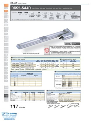
RCS2-SA4R ROBO Cylinder Slider Type 40mm Width 200V Servo Motor Side Mounted Motor
* See page Pre-35 for explanation of each code that makes up the configuration name.
Actuator Specifications
(1) When the stroke increases, the maximum speed will drop to prevent the
ball screw from reaching the critical rotational speed. Use the actuator
specification table below to check the maximum speed at the stroke you
desire.
(2) The load capacity is based on operation at an acceleration of 0.3G (0.2G
for the 2.5mm-lead model, or when used vertically).
These values are the upper limits for the acceleration.
O I N
■ Lead and Load Capacity ■ Stroke and Maximum Speed
Max. Load Capacity Rated
Model Stroke
Legend 1 Encoder 2 Stroke 3 Compatible controller 4 Cable length 5 Options
Encoder & Stroke List 4 Cable List
Type Cable Symbol Standard Price
Standard
Special Lengths
Robot Cable
P (1m)
S (3m)
M (5m)
X06 (6m) ~ X10 (10m)
X11 (11m) ~ X15 (15m)
X16 (16m) ~ X20 (20m)
R01 (1m) ~ R03 (3m)
R04 (4m) ~ R05 (5m)
R06 (6m) ~ R10 (10m)
R11 (11m) ~ R15 (15m)
R16 (16m) ~ R20 (20m)
—
—
—
—
—
—
—
—
—
—
—
* For cables for maintenance, see page A-39.
Standard Price
1 Encoder Type
5 Option List Actuator Specifications
Item Description
Ball screw Ø8mm C10 grade
±0.02mm
0.1mm or less
Material: Aluminum (white alumite treated)
Ma: 6.9N∙m Mb: 9.9N∙m Mc: 17.0N∙m
Ma: 2.7N∙m Mb: 3.9N∙m Mc: 6.8N∙m
Ma direction: 120mm or less Mb∙Mc direction: 120mm or less
0~40°C, 85% RH or less (Non-condensing)
Drive System
Positioning Repeatability
Lost Motion
Base
Allowable Static Moment
Allowable Dynamic Moment (*)
Overhang Load Length
Ambient Operating Temp./Humidity
Directions of Allowable Load Moments Overhang Load Length
L
L
Ma Mb Mc Ma Mc
–
–
–
–
–
–
–
–
–
–
–
–
–
–
–
–
50
100
150
200
250
300
350
400
Stroke
Lead
50 ~ 400
(50mm increments)
665
330
165
10
5
2.5
Name Option Code See Page Standard Price
B
HS
NM
ML
MR
SR
SS
Brake
Home sensor
Reversed-home
Left-Mounted Motor (Standard)
Right-Mounted Motor
Slider Roller
Slider spacer
(Unit: mm/s)
Motor
Output (W)
Lead
(mm) Horizontal (kg) Vertical (kg)
Thrust (N)
(mm)
RCS2-SA4R- 1 -20-10- 2 - 3 - 4 - 5
RCS2-SA4R- 1 -20-5- 2 - 3 - 4 - 5
RCS2-SA4R- 1 -20-2.5- 2 - 3 - 4 - 5
20
10
5
2.5
4
6
8
1
2.5
4.5
19.6
39.2
78.4
50 ~ 400
(50mm
increments)
Technical
References P. A-5
Pictured: Left-mounted motor model (ML).
→ A-25
→ A-32
→ A-33
→ A-33
→ A-33
→ A-36
→ A-36
—
—
—
—
—
—
—
(*) Based on 5,000km travel life.
Incremental Absolute
I A
2 Stroke (mm)
20: 20W Servo
motor
I : Incremental
A : Absolute
T1: XSEL-J/K
T2: SCON
SSEL
XSEL-P/Q
N : None
P : 1m
S : 3m
M : 5m
X □□ : Custom Length
R □□ : Robot Cable
See Options below
* Be sure to specify which
side the motor is to be
mounted (ML/MR).
50: 50mm
〜
400:400mm
(50mm pitch
increments)
10 : 10mm
5 : 5mm
2.5 : 2.5mm
■ Configuration: RCS2 SA4R 20
Series Type Encoder Motor Lead Stroke Compatible Controllers Cable Length Option
117 RCS2-SA4R
Slider
Type
Mini
Standard
Controllers
Integrated
Rod
Type
Mini
Standard
Controllers
Integrated
Table/Arm
/Flat Type
Mini
Standard
Gripper/
Rotary Type
Linear Servo
Type
Cleanroom
Type
Splash-Proof
Controllers
PMEC
/AMEC
PSEP
/ASEP
ROBO
NET
ERC2
PCON
ACON
SCON
PSEL
ASEL
SSEL
XSEL
Pulse Motor
Servo Motor
(24V)
Servo Motor
(200V)
Linear
Servo Motor
P
T
Notes on
Selection
Sold & Serviced By:
ELECTROMATE
Toll Free Phone (877) SERVO98
Toll Free Fax (877) SERV099
www.electromate.com
sales@electromate.com
2. CAD drawings can be
downloaded from IAI website. www.intelligentactuator.com
ø8 hole
slot
L
23 st 13 53.7
3
3
70
32
24
16±0.02
(Reamer hole
tolerance ±0.02)
10.2 11.8 M 11.8 53.9
93
46 7
Reference
surface
3.2
(40)
(37)
4
+0.010
3
0
ME SE Home ME *2
Secure at
least 100
98 (137 if brake-equipped) 23
RCS2 ROBO Cylinder
93
4-ø3.6
ø6.5 counterbore,
Depth 3.7
(for mounting actuator) *4
21
2-ø3H7 depth 5 4-M3 depth 7
Base
end-face
Base end-face
9
45
Details of the slot area
32
for adjusting slider position
Details of
oblong hole
Details of section A
(Actuator's reference side)
5
36.5
Actuator
width: 40
37
25
15
Bottom A
of base
Slider height: 40
22.5
1
31.2
Base end-face Base end-face
11.8 11.8
R 50
P (pitch for ø3 hole and oblong hole) 2-ø3H7 depth 5 from bottom of base
N (ø3 hole pitch)
m-M3 depth 5
Oblong hole depth 5 from bottom of base
21
Cable joint
connector *1
Ma moment offset
reference position *3
21
20
50 (when stroke is 50)
U×100P (All strokes except 50)
For Special Orders P. A-9
■ Dimensions/Weight by Stroke * Brake-equipped models are heavier by 0.3kg.
3 Compatible Controllers
The RCS2 series actuators can operate with the controllers below. Select the controller according to your usage.
Name External View Model Description Max. Positioning Points Input Voltage Power Supply Capacity Standard Price See Page
Positioner Mode
Pulse Train Input
Control Type
Program Control
1-6 Axis Type
SCON-C-201-NP-2-2 → P547
SSEL-C-1-201-NP-2-2
XSEL-3-1-201-N1-EEE-2-4
Solenoid Valve
Mode
Positioning is
possible for up to
512 points
512 points
Single-Phase AC
100V
Single-Phase AC
200V
3-Phase AC
200V
(XSEL-P/Q only)
360VA max.
* When
operating a
150W single-axis
model
Operable with
same controls as
solenoid valve.
7 points
Dedicated to serial
communication
64 points
Dedicated to
Pulse Train Input
(−)
Programmed
operation is possible
Can operate up to 2
axes
Programmed
operation is possible
Can operate up to 6
axes
20000 points
20000 points
→ P577
→ P587
—
—
—
Serial
Communication
Type
Program Control
1-2 Axis Type
* For SSEL and XSEL, only applicable to the single-axis model.
* 1 is a placeholder for the encoder type (I: incremental, A: absolute).
* 2 is a placeholder for the power supply voltage (1: 100V, 2: single-phase 200V, 3: 3-phase 200V).
* 3 is a placeholder for the XSEL type name (J, K, P, or Q).
* 4 is a placeholder for the power supply voltage (1: 100V, 2: single-phase 200V, 3: 3-phase 200V).
Dimensions
Stroke 50 100 150 200 250 300 350 400
L
M
N
P
R
U
m
Weight (kg)
209.7
122
50
35
22
−
4
0.8
259.7
172
100
85
22
1
4
0.9
309.7
222
100
85
72
1
4
1.0
359.7
272
200
185
22
2
6
1.1
409.7
322
200
185
72
2
6
1.2
459.7
372
300
285
22
3
8
1.3
509.7
422
300
285
72
3
8
1.4
559.7
472
400
385
22
4
10
1.5
*1 The motor-encoder cable is connected here. See page A-39 for details on cables.
*2 When homing, the slider moves to the ME; therefore, please watch for any interference with the
surrounding objects.
ME: Mechanical end SE: Stroke end
*3 Reference position for calculating the moment Ma.
*4 If the actuator is secured using only the mounting holes provided on the top surface of the base, the
base may twist to cause abnormal sliding of the slider, or may produce abnormal noise. Therefore,
when using the mounting holes on the top surface of the base, keep the stroke at 200mm or less.
RCS2-SA4R 118
Slider
Type
Mini
Standard
Controllers
Integrated
Rod
Type
Mini
Standard
Controllers
Integrated
Table/Arm
/Flat Type
Mini
Standard
Gripper/
Rotary Type
Linear Servo
Type
Cleanroom
Type
Splash-Proof
Controllers
PMEC
/AMEC
PSEP
/ASEP
ROBO
NET
ERC2
PCON
ACON
SCON
PSEL
ASEL
SSEL
XSEL
Pulse Motor
Servo Motor
(24V)
Servo Motor
(200V)
Linear
Servo Motor
Sold & Serviced By:
ELECTROMATE
Toll Free Phone (877) SERVO98
Toll Free Fax (877) SERV099
www.electromate.com
sales@electromate.com