Downloaded 1,186 times


![Revision History
No. Date Operator Notes
0 1/ 9/2007 Prodigy New vessel created Heat Exchanger. [Build 6252]
2/10/2007 10:33:19 AM 9/368](https://image.slidesharecdn.com/vesseldesign-120227013311-phpapp01/85/Vessel-design-10-320.jpg)


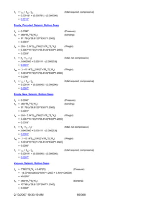


![Bottom Channel Section Stiffener
Stiffener ring calculations per UG-29(a)
Ring type: Flat bar
Ring description: 3/4x5 Flat Bar
Ring material: SA-36 (II-D p. 6, ln. 18)
External pressure: 15.0000 psi
Ring is located: outside the vessel
Distance from ring neutral axis to datum: 84.0000 in
Ring corrosion allowance: 0.1250 in
Distance to previous support: 55.7500 in
Distance to next support: 94.9375 in
L/Do = 94.9375/114.0000 = 0.8327851
Do/t = 114.0000/0.3495940 = 326.0926
From Table G: A = 0.000279
From Table HA-3: B = 3,669.08
Pa = 4*B/(3*(Do/t))
= 4*3,669.08/(3*(114.0000/0.3495940))
= 15.00221 psi
B = 0.75*P*Do/(t + As/Ls)
= 0.75*15*114/(0.3496 + 2.4375/75.34375)
= 3,357.754
From Table CS-2: A = 0.00023622 (ring, 325.00°F)
From Table HA-3: A = 0.00025540 (shell, 325.00°F)
Is' = [Do2*Ls*(t + As/Ls)*A]/10.9
= [1142*75.34375*(0.3496 + 2.4375/75.34375)*0.00025540]/10.9
= 8.763039 in4
I' for the composite corroded shell-ring cross section is 13.6815 in4
As I' >= Is' a 3/4x5 Flat Bar stiffener is adequate for an external pressure of 15.000 psi.
Check the stiffener ring attachment welds per UG-30
Fillet weld is: Continuous both sides
Fillet weld leg size: 0.2500 in
Vessel thickness at weld location, new: 0.3750 in
Vessel corrosion allowance at weld location: 0.0000 in
Stiffener thickness at weld location: 0.7500 in
Per UG-30(f)(1) the minimum attachment weld size is 0.2500 in
The fillet weld size of 0.25 in is adequate per UG-30(f)(1).
Radial pressure load, P*Ls = 15*75.34375 = 1,130.156 lb/in
Radial shear load, V = 0.01*P*Ls*Do = 0.01*15*75.34375*114 = 1,288.378 lb/in
First moment of area, Q = 2.697069*1.246149 = 3.360949 in3
Weld shear flow, q = V*Q/I' = 316.4985 lb/in
Combined weld load, fw = Sqr(1,130.1562 + 316.49852) = 1,173.637 lb/in
2/10/2007 10:33:19 AM 84/368](https://image.slidesharecdn.com/vesseldesign-120227013311-phpapp01/85/Vessel-design-85-320.jpg)

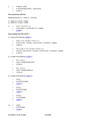
![Bottom Plate of Expanded Chamber
Stiffener ring calculations per UG-29(a)
Ring type: Flat bar
Ring description: 5/8x6 Flat Bar
Ring material: SA-240 304L (II-D p. 78, ln. 29)
External pressure: 15.0000 psi
Ring is located: outside the vessel
Distance from ring neutral axis to datum: 350.3750 in
Ring corrosion allowance: 0.0000 in
Distance to previous support: 47.0000 in
Distance to next support: 71.8750 in
L/Do = 71.875/114.0000 = 0.6304824
Do/t = 114.0000/0.3108990 = 366.6786
From Table G: A = 0.000314
From Table HA-3: B = 4,129.206
Pa = 4*B/(3*(Do/t))
= 4*4,129.206/(3*(114.0000/0.3108990))
= 15.01479 psi
B = 0.75*P*Do/(t + As/Ls)
= 0.75*15*114/(0.3109 + 3.75/59.4375)
= 3,429.222
From Table HA-3: A = 0.00026082 (ring, 325.00°F)
Is' = [Do2*Ls*(t + As/Ls)*A]/10.9
= [1142*59.4375*(0.3109 +
3.75/59.4375)*0.00026082]/10.9
= 6.912788 in4
I' for the composite corroded shell-ring cross section is 27.22062 in4
As I' >= Is' a 5/8x6 Flat Bar stiffener is adequate for an external pressure of 15.000 psi.
Check the stiffener ring attachment welds per UG-30
Fillet weld is: Continuous both sides
Fillet weld leg size: 0.3750 in
Vessel thickness at weld location, new: 0.3750 in
Vessel corrosion allowance at weld location: 0.0000 in
Stiffener thickness at weld location: 0.6250 in
Per UG-30(f)(1) the minimum attachment weld size is 0.2500 in
The fillet weld size of 0.375 in is adequate per UG-30(f)(1).
Radial pressure load, P*Ls = 15*59.4375 = 891.5625 lb/in
Radial shear load, V = 0.01*P*Ls*Do = 0.01*15*59.4375*114 = 1,016.381 lb/in
First moment of area, Q = 2.697069*1.85404 = 5.000474 in3
Weld shear flow, q = V*Q/I' = 186.711 lb/in
Combined weld load, fw = Sqr(891.56252 + 186.7112) = 910.9032 lb/in
2/10/2007 10:33:19 AM 86/368](https://image.slidesharecdn.com/vesseldesign-120227013311-phpapp01/85/Vessel-design-87-320.jpg)

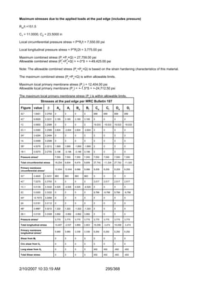
![Lower Calandria Stiffener RIngs
Stiffener ring calculations per UG-29(a)
Ring type: Flat bar
Ring description: 3/4x5 Flat Bar
Ring material: SA-36 (II-D p. 6, ln. 18)
External pressure: 15.0000 psi
Ring is located: outside the vessel
Distance from ring neutral axis to datum: 209.5000 in
Ring corrosion allowance: 0.1250 in
Distance to previous support: 69.0000 in
Distance to next support: 69.7500 in
L/Do = 69.75/114.0000 = 0.6118421
Do/t = 114.0000/0.3073280 = 370.9392
From Table G: A = 0.000318
From Table HA-3: B = 4,177.002
Pa = 4*B/(3*(Do/t))
= 4*4,177.002/(3*(114.0000/0.3073280))
= 15.01415 psi
B = 0.75*P*Do/(t + As/Ls)
= 0.75*15*114/(0.3073 + 2.4375/69.375)
= 3,745.235
From Table CS-2: A = 0.00026334 (ring, 325.00°F)
From Table HA-3: A = 0.00028482 (shell, 325.00°F)
Is' = [Do2*Ls*(t + As/Ls)*A]/10.9
= [1142*69.375*(0.3073 +
2.4375/69.375)*0.00028482]/10.9
= 8.06741 in4
I' for the composite corroded shell-ring cross section is 13.6815 in4
As I' >= Is' a 3/4x5 Flat Bar stiffener is adequate for an external pressure of 15.000 psi.
Check the stiffener ring attachment welds per UG-30
Fillet weld is: Continuous both sides
Fillet weld leg size: 0.2500 in
Vessel thickness at weld location, new: 0.3750 in
Vessel corrosion allowance at weld location: 0.0000 in
Stiffener thickness at weld location: 0.7500 in
Per UG-30(f)(1) the minimum attachment weld size is 0.2500 in
The fillet weld size of 0.25 in is adequate per UG-30(f)(1).
Radial pressure load, P*Ls = 15*69.375 = 1,040.625 lb/in
Radial shear load, V = 0.01*P*Ls*Do = 0.01*15*69.375*114 = 1,186.313 lb/in
First moment of area, Q = 2.697069*1.246149 = 3.360949 in3
Weld shear flow, q = V*Q/I' = 291.4254 lb/in
Combined weld load, fw = Sqr(1,040.6252 + 291.42542) = 1,080.662 lb/in
2/10/2007 10:33:19 AM 88/368](https://image.slidesharecdn.com/vesseldesign-120227013311-phpapp01/85/Vessel-design-89-320.jpg)

![Top Plate of Expanded Chamber
Stiffener ring calculations per UG-29(a)
Ring type: Flat bar
Ring description: 5/8x6 Flat Bar
Ring material: SA-240 304L (II-D p. 78, ln. 29)
External pressure: 15.0000 psi
Ring is located: outside the vessel
Distance from ring neutral axis to datum: 397.3750 in
Ring corrosion allowance: 0.0000 in
Distance to previous support: 16.6250 in
Distance to next support: 47.0000 in
L/Do = 47/114.0000 = 0.4122807
Do/t = 114.0000/0.2653050 = 429.6941
From Table G: A = 0.000380
From Table HA-3: B = 4,836.215
Pa = 4*B/(3*(Do/t))
= 4*4,836.215/(3*(114.0000/0.2653050))
= 15.00671 psi
B = 0.75*P*Do/(t + As/Ls)
= 0.75*15*114/(0.2653 + 3.75/31.8125)
= 3,347.007
From Table HA-3: A = 0.00025458 (ring, 325.00°F)
Is' = [Do2*Ls*(t + As/Ls)*A]/10.9
= [1142*31.8125*(0.2653 +
3.75/31.8125)*0.00025458]/10.9
= 3.700049 in4
I' for the composite corroded shell-ring cross section is 27.22062 in4
As I' >= Is' a 5/8x6 Flat Bar stiffener is adequate for an external pressure of 15.000 psi.
Check the stiffener ring attachment welds per UG-30
Fillet weld is: Continuous both sides
Fillet weld leg size: 0.3750 in
Vessel thickness at weld location, new: 0.3750 in
Vessel corrosion allowance at weld location: 0.0000 in
Stiffener thickness at weld location: 0.6250 in
Per UG-30(f)(1) the minimum attachment weld size is 0.2500 in
The fillet weld size of 0.375 in is adequate per UG-30(f)(1).
Radial pressure load, P*Ls = 15*31.8125 = 477.1875 lb/in
Radial shear load, V = 0.01*P*Ls*Do = 0.01*15*31.8125*114 = 543.9938 lb/in
First moment of area, Q = 2.697069*1.85404 = 5.000474 in3
Weld shear flow, q = V*Q/I' = 99.93259 lb/in
Combined weld load, fw = Sqr(477.18752 + 99.932592) = 487.5392 lb/in
2/10/2007 10:33:19 AM 90/368](https://image.slidesharecdn.com/vesseldesign-120227013311-phpapp01/85/Vessel-design-91-320.jpg)

![Upper Calandria Stiffener Ring
Stiffener ring calculations per UG-29(a)
Ring type: Flat bar
Ring description: 3/4x5 Flat Bar
Ring material: SA-36 (II-D p. 6, ln. 18)
External pressure: 15.0000 psi
Ring is located: outside the vessel
Distance from ring neutral axis to datum: 278.5000 in
Ring corrosion allowance: 0.1250 in
Distance to previous support: 71.8750 in
Distance to next support: 69.0000 in
L/Do = 71.875/114.0000 = 0.6304824
Do/t = 114.0000/0.3108990 = 366.6786
From Table G: A = 0.000314
From Table HA-3: B = 4,129.206
Pa = 4*B/(3*(Do/t))
= 4*4,129.206/(3*(114.0000/0.3108990))
= 15.01479 psi
B = 0.75*P*Do/(t + As/Ls)
= 0.75*15*114/(0.3109 + 2.4375/70.4375)
= 3,711.956
From Table CS-2: A = 0.00026101 (ring, 325.00°F)
From Table HA-3: A = 0.00028229 (shell, 325.00°F)
Is' = [Do2*Ls*(t + As/Ls)*A]/10.9
= [1142*70.4375*(0.3109 +
2.4375/70.4375)*0.00028229]/10.9
= 8.191082 in4
I' for the composite corroded shell-ring cross section is 13.6815 in4
As I' >= Is' a 3/4x5 Flat Bar stiffener is adequate for an external pressure of 15.000 psi.
Check the stiffener ring attachment welds per UG-30
Fillet weld is: Continuous both sides
Fillet weld leg size: 0.2500 in
Vessel thickness at weld location, new: 0.3750 in
Vessel corrosion allowance at weld location: 0.0000 in
Stiffener thickness at weld location: 0.7500 in
Per UG-30(f)(1) the minimum attachment weld size is 0.2500 in
The fillet weld size of 0.25 in is adequate per UG-30(f)(1).
Radial pressure load, P*Ls = 15*70.4375 = 1,056.563 lb/in
Radial shear load, V = 0.01*P*Ls*Do = 0.01*15*70.4375*114 = 1,204.481 lb/in
First moment of area, Q = 2.697069*1.246149 = 3.360949 in3
Weld shear flow, q = V*Q/I' = 295.8887 lb/in
Combined weld load, fw = Sqr(1,056.5632 + 295.88872) = 1,097.212 lb/in
2/10/2007 10:33:19 AM 92/368](https://image.slidesharecdn.com/vesseldesign-120227013311-phpapp01/85/Vessel-design-93-320.jpg)


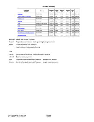
![= 0.925 * (1 + 1.7 * 3.40* 0.3048 * 0.9210) / (1 + 1.7 * 3.40 * 0.3048)
= 0.8784
Gust Factor Calculations: Vacuum, Corroded
z¯ = 0.60 * h
= 0.60 * 32.5573
= 30.0000
Iz¯ = c * (33 / z¯)1/6
= 0.3000 * (33 / 30.0000)1/6
= 0.3048
Lz¯ = l * (z¯ / 33)ep
= 320.0000 * (30.0000 / 33)0.3333
= 309.9934
Q = Sqr(1 / (1 + 0.63 * ((b + h) / Lz¯)0.63))
= Sqr(1 / (1 + 0.63 * ((9.5000 + 32.5573) / 309.9934)0.63))
= 0.9210
G = 0.925 * (1 + 1.7 * gQ * Iz¯ * Q) / (1 + 1.7 * gv * Iz¯)
= 0.925 * (1 + 1.7 * 3.40* 0.3048 * 0.9210) / (1 + 1.7 * 3.40 * 0.3048)
= 0.8784
Table Lookup Values
α = 7.0000, Zg = 1200.0000 ' [Table 6-2, page 78]
c = 0.3000, l = 320.0000, ep = 0.3333 [Table 6-2, page 78]
a¯ = 0.2500, b¯ = 0.4500 [Table 6-2, page 78]
gQ = 3.40 [6.5.8.1 page 26]
gv = 3.40 [6.5.8.1 page 26]
2/10/2007 10:33:19 AM 318/368](https://image.slidesharecdn.com/vesseldesign-120227013311-phpapp01/85/Vessel-design-319-320.jpg)


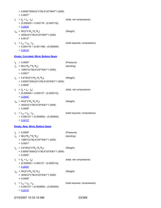
![αt,m =
Tubes SA-249 TP316L Wld tube Et =28.3E+06 St =26,471* Sy,t =25,000 N/A
8.50E-06
*The allowable tensile stress from Section II-D has been divided by 0.85 as the calculated stresses are longitudinal.
Material Properties at Operating Temperatures
Modulus of Allowable Yield
Operating
Condition Component Material Temperature Elasticity Stress Stress
(°F) (psi) (psi) (psi)
Shell SA-240 304L 254 27,230,000 16,700 20,120
Design
Channel SA-240 304L 250 27,250,000 16,700 20,200
Tubesheet SA-240 304 285 27,075,000 19,065 22,760
Tubes SA-249 TP316L Wld tube 282.50 27,087,500 16,706* 19,385
Shell SA-240 304L 254 27,230,000 16,700 20,120
Vacuum-SS
Channel SA-240 304L 250 27,250,000 16,700 20,200
Tubesheet SA-240 304 285 27,075,000 19,065 22,760
Tubes SA-249 TP316L Wld tube 282.50 27,087,500 16,706* 19,385
Shell SA-240 304L 254 27,230,000 16,700 20,120
Vacuum-TS
Channel SA-240 304L 250 27,250,000 16,700 20,200
Tubesheet SA-240 304 285 27,075,000 19,065 22,760
Tubes SA-249 TP316L Wld tube 282.50 27,087,500 16,706* 19,385
*The allowable tensile stress from Section II-D has been divided by 0.85 as the calculated stresses are longitudinal.
Calculations for Design Condition
UHX-13.5.1 Step 1
Do = 2*ro + dt
µ = (p - dt) / p
d* = MAX{[dt - 2*tt*(Et / E)*(St / S)*ρ], [dt - 2*tt]}
p* = p /(1 - 4*MIN(AL, 4*Do*p) /(π*Do2))0.5
µ* = (p* - d*)/p*
hg' = MAX[(hg - ct), 0] for pressure load only. For load cases 4, 5, 6, 7 hg' = 0.
ao = Do / 2
ρs = as / ao
ρc = ac / ao
xt = 1 - Nt*((dt - 2*tt)/(2*ao))2
xs = 1 - Nt*(dt/(2*ao))2
Condition Design
New or corroded Do = 2*53.2230 + 1.2500 = 107.6960
New or corroded µ = (1.6563 - 1.2500) /1.6563 = 0.2453
2/10/2007 10:33:19 AM 331/368](https://image.slidesharecdn.com/vesseldesign-120227013311-phpapp01/85/Vessel-design-332-320.jpg)
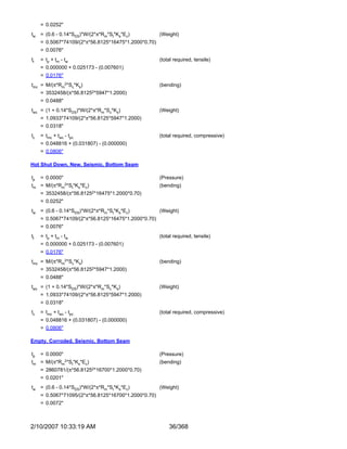
![*
d = MAX{[1.2500 - 2*0.0490*(26,850,000 / 26,850,000)*(16,471 / 18,750)*0.8500],
Load cases 1-3 1.1768267
New or corroded
[1.2500 - 2*0.0490]} =
*
d = MAX{[1.2500 - 2*0.0490*(27,087,500 / 27,075,000)*(16,706 / 19,065)*0.8500],
Load cases 4-7 1.1769739
[1.2500 - 2*0.0490]} =
New or corroded p* = 1.6563 /(1 - 4*MIN(560.0000, 4*107.6960*1.6563) /(π*107.69602))0.5 = 1.7097
New or corroded
Load cases 1-3 µ* = (1.7096848 - 1.1768267)/1.7096848 = 0.311670
Load cases 4-7 µ* = (1.7096848 - 1.1769739)/1.7096848 = 0.311584
hg' = 0.0000
New or corroded ao = 107.6960 / 2 = 53.8480
New or corroded ρs = 56.6250 / 53.8480 = 1.051571
New or corroded ρc = 56.6250 / 53.8480 = 1.051571
New or corroded xs = 1 - 3408*(1.2500/(2*53.8480))2 = 0.540886
New or corroded xt = 1 - 3408*((1.2500 - 2*0.0490)/(2*53.8480))2 = 0.610053
UHX-13.5.2 Step 2
Ks = π*ts*(Ds + ts)*Es / L
Kt = π*tt*(dt - tt)*Et / L
Ks,t = Ks / (Nt*Kt)
J = 1 / (1 + Ks/KJ)
βs = (12*(1 - νs2))0.25 / ((Ds + ts)*ts)0.5
ks = βs*Es*ts3 / (6*(1 - νs2))
λs = (6*Ds / h3)*ks*(1 + h*βs + h2*βs2 / 2)
δs = Ds2 / (4*Es*ts) * (1 - νs / 2)
βc = (12*(1 - νc2))0.25 / ((Dc + tc)*tc)0.5
kc = βc*Ec*tc3 / (6*(1 - νc2))
λc = (6*Dc / h3)*kc*(1 + h*βc + h2*βc2 / 2)
δc = Dc2 / (4*Ec*tc) * (1 - νc / 2)
Condition Design
Load cases
New or 1-3 Ks = π*0.3750*(113.2500 + 0.3750)*26,850,000 / 272.7500 = 13,177,547.00
corroded
Load cases
4-7 Ks = π*0.3750*(113.2500 + 0.3750)*27,230,000 / 272.7500 = 13,364,045.00
Load cases
New or 1-3 Kt = π*0.0490*(1.2500 - 0.0490)*26,850,000 / 272.7500 = 18,199.88
corroded
Load cases
4-7 Kt = π*0.0490*(1.2500 - 0.0490)*27,087,500 / 272.7500 = 18,360.86
Load cases
New or 1-3 Ks,t = 13,177,547.00 / (3408*18,199.88) = 0.212455
corroded
Load cases
4-7 Ks,t = 13,364,045.00 / (3408*18,360.86) = 0.213572
2/10/2007 10:33:19 AM 332/368](https://image.slidesharecdn.com/vesseldesign-120227013311-phpapp01/85/Vessel-design-333-320.jpg)
![Load cases
J = 1 as no expansion joint used
New or 1-3
corroded
Load cases
J = 1 as no expansion joint used
4-7
New or corroded βs = (12*(1 - 0.31002))0.25 / ((113.2500 + 0.3750)*0.3750)0.5 = 0.2780179
Load cases
New or 1-3 ks = 0.2780179*26,850,000*0.37503 / (6*(1 - 0.31002)) = 72,583.73
corroded
Load cases
4-7 ks = 0.2780179*27,230,000*0.37503 / (6*(1 - 0.31002)) = 73,610.98
Load cases λs = (6*113.2500 / 1.50003)*72,583.7266*(1 + 1.5000*0.2780179 +
1-3 21,978,486
New or 1.50002*0.27801792 / 2) =
corroded
Load cases λs = (6*113.2500 / 1.50003)*73,610.9844*(1 + 1.5000*0.2780179 +
4-7 22,289,542
1.50002*0.27801792 / 2) =
Load cases
New or 1-3 δs = 113.25002 / (4*26,850,000*0.3750) * (1 - 0.3100 / 2) = 2.6909E-04
corroded
Load cases
4-7 δs = 113.25002 / (4*27,230,000*0.3750) * (1 - 0.3100 / 2) = 2.6533E-04
New or corroded βc = (12*(1 - 0.30002))0.25 / ((113.2500 + 0.3750)*0.3750)0.5 = 0.2784858
Load cases
New or 1-3 kc = 0.2784858*26,850,000*0.37503 / (6*(1 - 0.30002)) = 72,218.51
corroded
Load cases
4-7 kc = 0.2784858*27,250,000*0.37503 / (6*(1 - 0.30002)) = 73,294.39
Load cases λc = (6*113.2500 / 1.50003)*72,218.5078*(1 + 1.5000*0.2784858 +
1-3 21,882,362
New or 1.50002*0.27848582 / 2) =
corroded
Load cases λc = (6*113.2500 / 1.50003)*73,294.3906*(1 + 1.5000*0.2784858 +
4-7 22,208,356
1.50002*0.27848582 / 2) =
Load cases
New or 1-3 δc = 113.25002 / (4*26,850,000*0.3750) * (1 - 0.3000 / 2) = 2.7068E-04
corroded
Load cases
4-7 δc = 113.25002 / (4*27,250,000*0.3750) * (1 - 0.3000 / 2) = 2.6671E-04
UHX-13.5.3 Step 3
E* / E = α0 + α1*µ* + α2*µ*2 + α3*µ*3 + α4*µ*4
ν* = β0 + β1*µ* + β2*µ*2 + β3*µ*3 + β4*µ*4
η = (E*/E)*(1 - ν2) / (1 - ν*2)
Xa = [24*(1 - ν*2)*Nt*Et*tt*(dt - tt)*ao2 / (E**L*h3)]0.25
Condition Design
New or corroded h/p = 1.5000/1.6563 = 0.9056
Load cases
New or 1-3 - from Fig. UHX-11.3(a) E*/E = 0.3370
corroded
Load cases
4-7 - from Fig. UHX-11.3(a) E*/E = 0.3369
Load cases
New or 1-3 E* = 0.3369805*26,850,000 = 9,047,927
corroded
Load cases
4-7 E* = 0.3368625*27,075,000 = 9,120,553
Load cases
New or 1-3 - from Fig. UHX-11.3(b) ν* = 0.3004
corroded
2/10/2007 10:33:19 AM 333/368](https://image.slidesharecdn.com/vesseldesign-120227013311-phpapp01/85/Vessel-design-334-320.jpg)
![Load cases
4-7 - from Fig. UHX-11.3(b) ν* = 0.3004
Load cases Xa = [24*(1 - 0.30039792)*3408*26,850,000*0.0490*(1.2500 - 0.0490)*53.84802 /
1-3 14.2239
New or (9,047,927*272.7500*1.50003)]0.25 =
corroded
Load cases Xa = [24*(1 - 0.30043602)*3408*27,087,500*0.0490*(1.2500 - 0.0490)*53.84802 /
4-7 14.2267
(9,120,553*272.7500*1.50003)]0.25 =
Load cases
New or 1-3 Zd = 0.0005076
corroded
Load cases
4-7 Zd = 0.0005073
Load cases
New or 1-3 Zv = 0.0050230
corroded
Load cases
4-7 Zv = 0.0050210
Load cases
New or 1-3 Zm = 0.1012484
corroded
Load cases
4-7 Zm = 0.1012277
UHX-13.5.4 Step 4
K = A / Do
F = ((1 - ν*) / E*)*(λs + λc + E*ln(K))
Φ = (1 + ν*)*F
Q1 = (ρs - 1 - Φ*Zv) / (1 + Φ*Zm)
Qz1 = (Zd + Q1*Zv)*Xa4 / 2
Qz2 = (Zv + Q1*Zm)*Xa4 / 2
U = [Zv + (ρs - 1)*Zm]*Xa4 / (1 +Φ*Zm)
Condition Design
New or corroded K = 116.0000 / 107.6960 = 1.0771059
Load cases F = ((1 - 0.3003979) / 9,047,927)*(21,978,486.00 + 21,882,362.00 +
1-3 3.5456076
New or corroded
26,850,000*ln(1.0771)) =
Load cases F = ((1 - 0.3004360) / 9,120,553)*(22,289,542.00 + 22,208,356.00 +
4-7 3.5673274
27,075,000*ln(1.0771)) =
Load cases
1-3 Φ = (1 + 0.3003979)*3.5456076 = 4.6107008
New or corroded
Load cases
4-7 Φ = (1 + 0.3004360)*3.5673274 = 4.6390811
Load cases
1-3 Q1 = (1.0515711 - 1 - 4.6107008*0.0050230) / (1 + 4.6107008*0.1012484) = 0.0193694
New or corroded
Load cases
4-7 Q1 = (1.0515711 - 1 - 4.6390811*0.0050210) / (1 + 4.6390811*0.1012277) = 0.0192421
Load cases
1-3 Qz1 = (0.0005076 + 0.0193694*0.0050230)*14.22388644 / 2 = 12.3795
New or corroded
Load cases
4-7 Qz1 = (0.0005073 + 0.0192421*0.0050210)*14.22668374 / 2 = 12.3692
Load cases
1-3 Qz2 = (0.0050230 + 0.0193694*0.1012484)*14.22388644 / 2 = 142.9404
New or corroded
2/10/2007 10:33:19 AM 334/368](https://image.slidesharecdn.com/vesseldesign-120227013311-phpapp01/85/Vessel-design-335-320.jpg)
![Load cases
4-7 Qz2 = (0.0050210 + 0.0192421*0.1012277)*14.22668374 / 2 = 142.7397
Load cases U = [0.0050230 + (1.0515711 - 1)*0.1012484]*14.22388644 / (1 +4.6107008*0.1012484)
1-3 285.8809
New or corroded
=
Load cases U = [0.0050210 + (1.0515711 - 1)*0.1012277]*14.22668374 / (1 +4.6390811*0.1012277)
4-7 285.4795
=
UHX-13.5.5 Step
5
γb = 0
Tr = (T' + Ts' + Tc')
/3
Condition Design
New
or γb = 0 = 0
corroded
UHX-13.5.5 Step 5
γ = [αt,m*(Tt,m - Ta) - αs,m*(Ts,m - Ta)]*L
ωs = ρs*ks*βs*δs*(1 + h*βs)
ωc = ρc*kc*βc*δc*(1 + h*βc)
ωs* = ao2*(ρs2 - 1)*(ρs - 1) / 4 - ωs
ωc* = ao2*[(ρc2 + 1)*(ρc - 1) / 4 - (ρs - 1) / 2] - ωc
Condition Design
Ps (psi) Pt (psi)
Load Case 1 0 50
Load Case 2 50 0
Load Case 3 50 50
Load Case 4 0 0
Load Case 5 0 50
Load Case 6 50 0
Load Case 7 50 50
New or
Load case 1, 2, 3 γ= 0.0000
corroded
Load case 4, 5, 6,
7 γ = [9.17E-06*(282.50 - 70) - 9.11E-06*(254.50 - 70)]*272.7500 = 0.0728111
New or
corroded
All load cases ωs = 1.0515711*72,583.7266*0.2780179*2.690900E-04*(1 + 1.5000*0.2780179) = 8.0915
New or
corroded
All load cases ωs* = 53.84802*(1.05157112 - 1)*(1.0515711 - 1) / 4 - 8.0914516 = -4.1362
New or
corroded
All load cases ωc = 1.0515711*72,218.5078*0.2784858*2.706823E-04*(1 + 1.5000*0.2784858) = 8.1160
2/10/2007 10:33:19 AM 335/368](https://image.slidesharecdn.com/vesseldesign-120227013311-phpapp01/85/Vessel-design-336-320.jpg)
![New or ωc* = 53.84802*[(1.05157112 + 1)*(1.0515711 - 1) / 4 - (1.0515711 - 1) / 2] - 8.1160212
corroded
All load cases -4.1607
=
UHX-13.5.6 Step 6
Ps' = (xs + 2*(1 - xs)*νt + 2 / Ks,t*(Ds / Do)2*νs - (ρs2 - 1) / (J*Ks,t) - (1 - J)*[Dj2 - (2*as)2] / (2*J*Ks,t*Do2))*Ps
Pt' = (xt + 2*(1 - xt)*νt + 1 / (J*Ks,t))*Pt
Pγ = Nt*Kt*γ / (π*ao2)
PW = - U*γb*W / (2*π*ao2)
Prim = - U / ao2*(ωs**Ps - ωc**Pt)
Pe = J*Ks,t / (1 + J*Ks,t*[QZ1 + (ρs - 1)*QZ2] )*(Ps' - Pt' + Pγ + PW + Prim)
Condition Design
Ps' = (0.5408861 + 2*(1 - 0.5408861)*0.3000 + 2 / 0.2124548*(113.2500 / 107.6960)2*0.3100 -
Load case
1, 4, 5 (1.05157112 - 1) / (1.0000000*0.2124548) - (1 - 1.0000000)*[0.00002 - (2*56.6250)2] / 0
(2*1.0000000*0.2124548*107.69602))*0 =
New or
corroded
Ps' = (0.5408861 + 2*(1 - 0.5408861)*0.3000 + 2 / 0.2124548*(113.2500 / 107.6960)2*0.3100 -
Load case
2, 3 (1.05157112 - 1) / (1.0000000*0.2124548) - (1 - 1.0000000)*[0.00002 - (2*56.6250)2] / 177.27
(2*1.0000000*0.2124548*107.69602))*50 =
Ps' = (0.5408861 + 2*(1 - 0.5408861)*0.3000 + 2 / 0.2135724*(113.2500 / 107.6960)2*0.3100 -
Load case
6, 7 (1.05157112 - 1) / (1.0000000*0.2135724) - (1 - 1.0000000)*[0.00002 - (2*56.6250)2] / 176.56
(2*1.0000000*0.2135724*107.69602))*50 =
Load case
1, 3 Pt' = (0.6100532 + 2*(1 - 0.6100532)*0.3000 + 1 / (1.0000000*0.2124548))*50 = 277.55
New or
corroded Load case
2, 4, 6 Pt' = (0.6100532 + 2*(1 - 0.6100532)*0.3000 + 1 / (1.0000000*0.2124548))*0 = 0
Load case
5, 7 Pt' = (0.6100532 + 2*(1 - 0.6100532)*0.3000 + 1 / (1.0000000*0.2135724))*50 = 276.31
Load case
New or 1, 2, 3 Pγ = 3408*18,199.88*0.0000000 / (π*53.84802) = 0
corroded
Load case
4, 5, 6, 7 Pγ = 3408*18,360.86*0.0728111 / (π*53.84802) = 500.15
New or All load
corroded cases PW = - 285.8808731*0*0.00 / (2*π*53.84802) = 0
Load case
1 Prim = - 285.8808731 / 53.84802*(-4.1361599*0 - -4.1607299*50) = -20.51
Load case
2 Prim = - 285.8808731 / 53.84802*(-4.1361599*50 - -4.1607299*0) = 20.39
New or
Load case
corroded
3 Prim = - 285.8808731 / 53.84802*(-4.1361599*50 - -4.1607299*50) = -0.12
Load case
4 Prim = - 285.4794649 / 53.84802*(-4.1361599*0 - -4.1607299*0) = 0
Load case
5 Prim = - 285.4794649 / 53.84802*(-4.1361599*0 - -4.1607299*50) = -20.48
Load case
6 Prim = - 285.4794649 / 53.84802*(-4.1361599*50 - -4.1607299*0) = 20.36
Load case
7 Prim = - 285.4794649 / 53.84802*(-4.1361599*50 - -4.1607299*50) = -0.12
Load case Pe = 1.0000000*0.2124548 / (1 + 1.0000000*0.2124548*[12.3795336 + (1.0515711 -
1 -12.19
1)*142.9404365] )*(0 - 277.5453 + 0 + 0 + -20.5109) =
2/10/2007 10:33:19 AM 336/368
New or
corroded](https://image.slidesharecdn.com/vesseldesign-120227013311-phpapp01/85/Vessel-design-337-320.jpg)
![Load case Pe = 1.0000000*0.2124548 / (1 + 1.0000000*0.2124548*[12.3795336 + (1.0515711 -
2 8.08
1)*142.9404365] )*(177.2692 - 0 + 0 + 0 + 20.3898) =
Load case Pe = 1.0000000*0.2124548 / (1 + 1.0000000*0.2124548*[12.3795336 + (1.0515711 -
3 -4.10
1)*142.9404365] )*(177.2692 - 277.5453 + 0 + 0 + -0.1211) =
Load case Pe = 1.0000000*0.2135724 / (1 + 1.0000000*0.2135724*[12.3691774 + (1.0515711 -
4 20.49
1)*142.7397324] )*(0 - 0 + 500.1513 + 0 + 0) =
Load case Pe = 1.0000000*0.2135724 / (1 + 1.0000000*0.2135724*[12.3691774 + (1.0515711 -
5 8.33
1)*142.7397324] )*(0 - 276.3137 + 500.1513 + 0 + -20.4821) =
Load case Pe = 1.0000000*0.2135724 / (1 + 1.0000000*0.2135724*[12.3691774 + (1.0515711 -
6 28.55
1)*142.7397324] )*(176.5551 - 0 + 500.1513 + 0 + 20.3612) =
Load case Pe = 1.0000000*0.2135724 / (1 + 1.0000000*0.2135724*[12.3691774 + (1.0515711 -
7 16.40
1)*142.7397324] )*(176.5551 - 276.3137 + 500.1513 + 0 + -0.1210) =
UHX-13.5.7 Step 7
Q2 = ((ωs**Ps - ωc**Pt) + γb*W / (2*π)) / (1 + Φ*Zm)
Q3 = Q1 + 2*Q2 / (Pe*ao2)
Fm is calculated per Table UHX-13.1
σ = (1.5*Fm / µ*)*(2*ao / (h - hg'))2*Pe
Condition Design
Load case 1 Q2 = ((-4.1361599*0 - -4.1607299*50) + 0*0.00 / (2*π)) / (1 + 4.6107008*0.1012484) = 141.8277
Load case 2 Q2 = ((-4.1361599*50 - -4.1607299*0) + 0*0.00 / (2*π)) / (1 + 4.6107008*0.1012484) = -140.9902
New or corroded
Load case 3 Q2 = ((-4.1361599*50 - -4.1607299*50) + 0*0.00 / (2*π)) / (1 + 4.6107008*0.1012484) = 0.8375211
Load case 4 Q2 = ((-4.1361599*0 - -4.1607299*0) + 0*0.00 / (2*π)) / (1 + 4.6390811*0.1012277) = 0.0000000
Load case 5 Q2 = ((-4.1361599*0 - -4.1607299*50) + 0*0.00 / (2*π)) / (1 + 4.6390811*0.1012277) = 141.5596
Load case 6 Q2 = ((-4.1361599*50 - -4.1607299*0) + 0*0.00 / (2*π)) / (1 + 4.6390811*0.1012277) = -140.7237
Load case 7 Q2 = ((-4.1361599*50 - -4.1607299*50) + 0*0.00 / (2*π)) / (1 + 4.6390811*0.1012277) = 0.8359380
Load case 1 Q3 = 0.0193694 + 2*141.8277 / (-12.1864*53.84802) = 0.0113420
Load case 2 Q3 = 0.0193694 + 2*-140.9902 / (8.0816*53.84802) = 0.0073361
New or corroded
Load case 3 Q3 = 0.0193694 + 2*0.8375211 / (-4.1049*53.84802) = 0.0192287
Load case 4 Q3 = 0.0192421 + 2*0.0000000 / (20.4874*53.84802) = 0.0192421
Load case 5 Q3 = 0.0192421 + 2*141.5596 / (8.3299*53.84802) = 0.0309638
Load case 6 Q3 = 0.0192421 + 2*-140.7237 / (28.5535*53.84802) = 0.0158427
Load case 7 Q3 = 0.0192421 + 2*0.8359380 / (16.3961*53.84802) = 0.0192773
Stress Allowable Over-
Tubesheet Bending Stress (psi) (psi) stressed?
σ = (1.5*0.0203531 / 0.3116704)*(2*53.8480 / (1.5000 -
Load case 1 -6,153 28,125 No
0.0000))2*-12.1864 =
σ = (1.5*0.0190249 / 0.3116704)*(2*53.8480 / (1.5000 - 0.0000))2*8.0816
Load case 2 3,814 28,125 No
=
New or corroded σ = (1.5*0.0233922 / 0.3116704)*(2*53.8480 / (1.5000 - 0.0000))2*-4.1049
Load case 3 -2,382 28,125 No
=
Load case 4 11,894 57,195 No
2/10/2007 10:33:19 AM 337/368](https://image.slidesharecdn.com/vesseldesign-120227013311-phpapp01/85/Vessel-design-338-320.jpg)
![σ = (1.5*0.0233946 / 0.3115843)*(2*53.8480 / (1.5000 -
0.0000))2*20.4874 =
σ = (1.5*0.0280129 / 0.3115843)*(2*53.8480 / (1.5000 - 0.0000))2*8.3299
Load case 5 5,791 57,195 No
=
σ = (1.5*0.0220552 / 0.3115843)*(2*53.8480 / (1.5000 -
Load case 6 15,628 57,195 No
0.0000))2*28.5535 =
σ = (1.5*0.0234084 / 0.3115843)*(2*53.8480 / (1.5000 -
Load case 7 9,525 57,195 No
0.0000))2*16.3961 =
UHX-13.5.8 Step 8
τ = (1 / (2*µ))*(ao / h)*Pe
Condition Design
Stress Allowable Over-
Tubesheet Shear Stress (psi) (psi) stressed?
Load case 1 τ = (1 / (2*0.2453))*(53.8480 / 1.5000)*-12.1864 = -892 15,000 No
Load case 2 τ = (1 / (2*0.2453))*(53.8480 / 1.5000)*8.0816 = 591 15,000 No
New or corroded
Load case 3 τ = (1 / (2*0.2453))*(53.8480 / 1.5000)*-4.1049 = -300 15,000 No
Load case 4 τ = (1 / (2*0.2453))*(53.8480 / 1.5000)*20.4874 = 1,499 15,252 No
Load case 5 τ = (1 / (2*0.2453))*(53.8480 / 1.5000)*8.3299 = 610 15,252 No
Load case 6 τ = (1 / (2*0.2453))*(53.8480 / 1.5000)*28.5535 = 2,089 15,252 No
Load case 7 τ = (1 / (2*0.2453))*(53.8480 / 1.5000)*16.3961 = 1,200 15,252 No
UHX-13.5.9 Step 9
Fq = (Zd + Q3*Zv)*Xa4 / 2
Fs = MAX [(3.25 - 0.5*Fq), 1.25] but not greater than 2.0
σt,o = ((Ps*xs - Pt*xt) - Pe*Fq) / (xt - xs)
lt = k*l
rt = (dt2 + (dt - 2*tt)2 )0.5 / 4
Ft = lt / rt
Ct = (2*π2*Et / Sy,t)0.5
For Ct <= Ft, Stb = Min{π2*Et / (Fs*Ft2), St}
For Ct > Ft, Stb = Min{Sy,t / Fs*(1 - Ft/ (2*Ct)), St}
Condition Design
Load case 1 Fq = (0.0005076 + 0.0113420*0.0050230)*14.22388644 / 2 = 11.5543
New or Load case 2 Fq = (0.0005076 + 0.0073361*0.0050230)*14.22388644 / 2 = 11.1425
corroded
Load case 3 Fq = (0.0005076 + 0.0192287*0.0050230)*14.22388644 / 2 = 12.3651
Load case 4 Fq = (0.0005073 + 0.0192421*0.0050210)*14.22668374 / 2 = 12.3692
Load case 5 Fq = (0.0005073 + 0.0309638*0.0050210)*14.22668374 / 2 = 13.5747
2/10/2007 10:33:19 AM 338/368](https://image.slidesharecdn.com/vesseldesign-120227013311-phpapp01/85/Vessel-design-339-320.jpg)
![Load case 6 Fq = (0.0005073 + 0.0158427*0.0050210)*14.22668374 / 2 = 12.0196
Load case 7 Fq = (0.0005073 + 0.0192773*0.0050210)*14.22668374 / 2 = 12.3728
New or
All load cases rt = (1.25000002 + (1.2500000 - 2*0.0490000)2 )0.5 / 4 = 0.4250
corroded
New or
All load cases Ft = 87.3000 / 0.4250 = 205.4258
corroded
Load case 1 Ct = 0
New or
corroded Load case 2, 3 Ct = (2*π2*26,850,000 / 18,625)0.5 = 168.6898
Load case 4, 5,
Ct = (2*π2*27,087,500 / 19,385)0.5 = 166.0797
6, 7
New or
All load cases Fs = MAX [(3.25 - 0.5*11.5542910) = -2.5271, 1.25] but not greater than 2.0 = 1.2500
corroded
Stress Allowable Over-
Tube Evaluation (psi) (psi) stressed?
σt,o = ((0*0.5408861 - 50*0.6100532) - -12.1864*11.5542910) /
Load case 1 1,595 16,471 No
(0.6100532 - 0.5408861) =
σt,o = ((50*0.5408861 - 0*0.6100532) - 8.0816*11.1424730) / (0.6100532
Load case 2 -911 16,471 No
- 0.5408861) =
σt,o = ((50*0.5408861 - 50*0.6100532) - -4.1049*12.3650662) /
New or Load case 3 684 16,471 No
corroded (0.6100532 - 0.5408861) =
σt,o = ((0*0.5408861 - 0*0.6100532) - 20.4874*12.3691774) / (0.6100532
Load case 4 -3,664 33,412 No
- 0.5408861) =
σt,o = ((0*0.5408861 - 50*0.6100532) - 8.3299*13.5746696) / (0.6100532
Load case 5 -2,076 33,412 No
- 0.5408861) =
σt,o = ((50*0.5408861 - 0*0.6100532) - 28.5535*12.0195759) /
Load case 6 -4,571 33,412 No
(0.6100532 - 0.5408861) =
σt,o = ((50*0.5408861 - 50*0.6100532) - 16.3961*12.3727940) /
Load case 7 -2,983 33,412 No
(0.6100532 - 0.5408861) =
Load case 1, 3 Stb = 0 No
New or
corroded
Load case 2 For Ct <= 205.4258, Stb = Min{π2*26,850,000 / (1.2500*205.42582) = 5,024, 16,471} = 5,024 No
Load case 4, 5,
6, 7
For Ct <= 205.4258, Stb = Min{π2*27,087,500 / (1.2500*205.42582) = 5,068, 16,706} = 5,068 No
UHX-13.5.10 Step 10
σs,m = ao2 / (ts*(2*as + ts))*[Pe + (ρs2 - 1)*(Ps - Pt)] + as2*Pt / (ts*(2*as + ts))
σs,b = 6*ks / ts2*{βs*[δs*Ps - νs*as*σs,m/ Es] + 6*(1 - ν*2) / E**(ao3 / h3)*(1 + h*βs / 2)*[Pe*(Zv + Zm*Q1) + 2*Zm*Q2 / ao2]}
σs = ABS(σs,m) + ABS(σs,b)
σc,m = ac2 / (tc*(2*ac + tc))*Pt
σc,b = 6*kc / tc2*{βc*δc*Pt - 6*(1 - ν*2) / E**(ao3 / h3)*(1 + h*βc / 2)*[Pe*(Zv + Zm*Q1) + 2*Zm*Q2 / ao2]}
σc = ABS(σc,m) + ABS(σc,b)
Condition Design
Minimum shell length = 1.8*(Ds*ts)0.5 = 11.7302 in where thickness ts = 0.3750 in
Stress 1.5*Ss SPS,s Over-
Shell Evaluation (psi) (psi) (psi) stressed?
2/10/2007 10:33:19 AM 339/368](https://image.slidesharecdn.com/vesseldesign-120227013311-phpapp01/85/Vessel-design-340-320.jpg)

![σc,b = 6*72,218.5078 / 0.37502*(0.2784858*2.706823E-04*50 - 6*(1 - 0.30039792) / 9,047,927*(53.84803 /
1.50003)*(1 + 1.5000*0.2784858 / 2)*(-12.1864*(0.0050230 + 0.1012484*0.0193694) + 2*0.1012484*141.8277 / 19,432
53.84802)) =
σc = ABS(3,763) + ABS(19,432) = 23,195
σc,m = 56.62502 / (0.3750*(2*56.6250 + 0.3750))*0 = 0
Load
case
σc,b = 6*72,218.5078 / 0.37502*(0.2784858*2.706823E-04*0 - 6*(1 - 0.30039792) / 9,047,927*(53.84803 /
24,713 49,425 No
2
1.50003)*(1 + 1.5000*0.2784858 / 2)*(8.0816*(0.0050230 + 0.1012484*0.0193694) + 2*0.1012484*-140.9902 / -4,844
53.84802)) =
σc = ABS(0) + ABS(-4,844) = 4,844
σc,m = 56.62502 / (0.3750*(2*56.6250 + 0.3750))*50 = 3,763
Load
case
σc,b = 6*72,218.5078 / 0.37502*(0.2784858*2.706823E-04*50 - 6*(1 - 0.30039792) / 9,047,927*(53.84803 /
24,713 49,425 No
3
1.50003)*(1 + 1.5000*0.2784858 / 2)*(-4.1049*(0.0050230 + 0.1012484*0.0193694) + 2*0.1012484*0.8375211 / 14,588
53.84802)) =
σc = ABS(3,763) + ABS(14,588) = 18,351
σc,m = 56.62502 / (0.3750*(2*56.6250 + 0.3750))*0 = 0
Load
case
σc,b = 6*73,294.3906 / 0.37502*(0.2784858*2.667090E-04*0 - 6*(1 - 0.30043602) / 9,120,553*(53.84803 /
N/A 50,100 No
4
1.50003)*(1 + 1.5000*0.2784858 / 2)*(20.4874*(0.0050210 + 0.1012277*0.0192421) + 2*0.1012277*0.0000000 / -14,944
53.84802)) =
σc = ABS(0) + ABS(-14,944) = 14,944
σc,m = 56.62502 / (0.3750*(2*56.6250 + 0.3750))*50 = 3,763
Load
case
σc,b = 6*73,294.3906 / 0.37502*(0.2784858*2.667090E-04*50 - 6*(1 - 0.30043602) / 9,120,553*(53.84803 /
N/A 50,100 No
5
1.50003)*(1 + 1.5000*0.2784858 / 2)*(8.3299*(0.0050210 + 0.1012277*0.0192421) + 2*0.1012277*141.5596 / 4,503
53.84802)) =
σc = ABS(3,763) + ABS(4,503) = 8,266
σc,m = 56.62502 / (0.3750*(2*56.6250 + 0.3750))*0 = 0
Load
case
σc,b = 6*73,294.3906 / 0.37502*(0.2784858*2.667090E-04*0 - 6*(1 - 0.30043602) / 9,120,553*(53.84803 /
N/A 50,100 No
6
1.50003)*(1 + 1.5000*0.2784858 / 2)*(28.5535*(0.0050210 + 0.1012277*0.0192421) + 2*0.1012277*-140.7237 / -19,799
53.84802)) =
σc = ABS(0) + ABS(-19,799) = 19,799
σc,m = 56.62502 / (0.3750*(2*56.6250 + 0.3750))*50 = 3,763
Load
case
σc,b = 6*73,294.3906 / 0.37502*(0.2784858*2.667090E-04*50 - 6*(1 - 0.30043602) / 9,120,553*(53.84803 /
N/A 50,100 No
7
1.50003)*(1 + 1.5000*0.2784858 / 2)*(16.3961*(0.0050210 + 0.1012277*0.0192421) + 2*0.1012277*0.8359380 / -352
53.84802)) =
σc = ABS(3,763) + ABS(-352) = 4,115
Calculations for Vacuum-SS Condition
UHX-13.5.1 Step 1
Condition Vacuum-SS
New or corroded Do = 2*53.2230 + 1.2500 = 107.6960
New or corroded µ = (1.6563 - 1.2500) /1.6563 = 0.2453
*
d = MAX{[1.2500 - 2*0.0490*(26,850,000 / 26,850,000)*(16,471 / 18,750)*0.8500],
Load cases 1-3 1.1768267
New or corroded
[1.2500 - 2*0.0490]} =
*
d = MAX{[1.2500 - 2*0.0490*(27,087,500 / 27,075,000)*(16,706 / 19,065)*0.8500],
Load cases 4-7 1.1769739
[1.2500 - 2*0.0490]} =
New or corroded p* = 1.6563 /(1 - 4*MIN(560.0000, 4*107.6960*1.6563) /(π*107.69602))0.5 = 1.7097
New or corroded
Load cases 1-3 µ* = (1.7096848 - 1.1768267)/1.7096848 = 0.311670
Load cases 4-7 µ* = (1.7096848 - 1.1769739)/1.7096848 = 0.311584
2/10/2007 10:33:19 AM 341/368](https://image.slidesharecdn.com/vesseldesign-120227013311-phpapp01/85/Vessel-design-342-320.jpg)

![Load cases
New or 1-3 δc = 113.25002 / (4*26,850,000*0.3750) * (1 - 0.3000 / 2) = 2.7068E-04
corroded
Load cases
4-7 δc = 113.25002 / (4*27,250,000*0.3750) * (1 - 0.3000 / 2) = 2.6671E-04
UHX-13.5.3 Step 3
Condition Vacuum-SS
New or corroded h/p = 1.5000/1.6563 = 0.9056
Load cases
New or 1-3 - from Fig. UHX-11.3(a) E*/E = 0.3370
corroded
Load cases
4-7 - from Fig. UHX-11.3(a) E*/E = 0.3369
Load cases
New or 1-3 E* = 0.3369805*26,850,000 = 9,047,927
corroded
Load cases
4-7 E* = 0.3368625*27,075,000 = 9,120,553
Load cases
New or 1-3 - from Fig. UHX-11.3(b) ν* = 0.3004
corroded
Load cases
4-7 - from Fig. UHX-11.3(b) ν* = 0.3004
Load cases Xa = [24*(1 - 0.30039792)*3408*26,850,000*0.0490*(1.2500 - 0.0490)*53.84802 /
1-3 14.2239
New or (9,047,927*272.7500*1.50003)]0.25 =
corroded
Load cases Xa = [24*(1 - 0.30043602)*3408*27,087,500*0.0490*(1.2500 - 0.0490)*53.84802 /
4-7 14.2267
(9,120,553*272.7500*1.50003)]0.25 =
Load cases
New or 1-3 Zd = 0.0005076
corroded
Load cases
4-7 Zd = 0.0005073
Load cases
New or 1-3 Zv = 0.0050230
corroded
Load cases
4-7 Zv = 0.0050210
Load cases
New or 1-3 Zm = 0.1012484
corroded
Load cases
4-7 Zm = 0.1012277
UHX-13.5.4 Step 4
Condition Vacuum-SS
New or corroded K = 116.0000 / 107.6960 = 1.0771059
Load cases F = ((1 - 0.3003979) / 9,047,927)*(21,978,486.00 + 21,882,362.00 +
1-3 3.5456076
New or corroded
26,850,000*ln(1.0771)) =
Load cases F = ((1 - 0.3004360) / 9,120,553)*(22,289,542.00 + 22,208,356.00 +
4-7 3.5673274
27,075,000*ln(1.0771)) =
Load cases
1-3 Φ = (1 + 0.3003979)*3.5456076 = 4.6107008
New or corroded
Load cases
4-7 Φ = (1 + 0.3004360)*3.5673274 = 4.6390811
Q1 = (1.0515711 - 1 - 4.6107008*0.0050230) / (1 + 4.6107008*0.1012484) = 0.0193694
New or corroded
2/10/2007 10:33:19 AM 343/368](https://image.slidesharecdn.com/vesseldesign-120227013311-phpapp01/85/Vessel-design-344-320.jpg)
![Load cases
1-3
Load cases
4-7 Q1 = (1.0515711 - 1 - 4.6390811*0.0050210) / (1 + 4.6390811*0.1012277) = 0.0192421
Load cases
1-3 Qz1 = (0.0005076 + 0.0193694*0.0050230)*14.22388644 / 2 = 12.3795
New or corroded
Load cases
4-7 Qz1 = (0.0005073 + 0.0192421*0.0050210)*14.22668374 / 2 = 12.3692
Load cases
1-3 Qz2 = (0.0050230 + 0.0193694*0.1012484)*14.22388644 / 2 = 142.9404
New or corroded
Load cases
4-7 Qz2 = (0.0050210 + 0.0192421*0.1012277)*14.22668374 / 2 = 142.7397
Load cases U = [0.0050230 + (1.0515711 - 1)*0.1012484]*14.22388644 / (1 +4.6107008*0.1012484)
1-3 285.8809
New or corroded
=
Load cases U = [0.0050210 + (1.0515711 - 1)*0.1012277]*14.22668374 / (1 +4.6390811*0.1012277)
4-7 285.4795
=
UHX-13.5.5 Step 5
Condition
Vacuum-SS
New
or γb = 0 = 0
corroded
UHX-13.5.5 Step 5
Condition Vacuum-SS
Ps (psi) Pt (psi)
Load Case 1 0 50
Load Case 2 -15 0
Load Case 3 -15 50
Load Case 4 0 0
Load Case 5 0 50
Load Case 6 -15 0
Load Case 7 -15 50
New or
Load case 1, 2, 3 γ= 0.0000
corroded
Load case 4, 5, 6,
7 γ = [9.17E-06*(282.50 - 70) - 9.11E-06*(254.50 - 70)]*272.7500 = 0.0728111
New or
corroded
All load cases ωs = 1.0515711*72,583.7266*0.2780179*2.690900E-04*(1 + 1.5000*0.2780179) = 8.0915
New or
corroded
All load cases ωs* = 53.84802*(1.05157112 - 1)*(1.0515711 - 1) / 4 - 8.0914516 = -4.1362
New or
corroded
All load cases ωc = 1.0515711*72,218.5078*0.2784858*2.706823E-04*(1 + 1.5000*0.2784858) = 8.1160
New or ωc* = 53.84802*[(1.05157112 + 1)*(1.0515711 - 1) / 4 - (1.0515711 - 1) / 2] - 8.1160212
corroded
All load cases -4.1607
=
2/10/2007 10:33:19 AM 344/368](https://image.slidesharecdn.com/vesseldesign-120227013311-phpapp01/85/Vessel-design-345-320.jpg)
![UHX-13.5.6 Step 6
Condition Vacuum-SS
Ps' = (0.5408861 + 2*(1 - 0.5408861)*0.3000 + 2 / 0.2124548*(113.2500 / 107.6960)2*0.3100 -
Load case
1, 4, 5 (1.05157112 - 1) / (1.0000000*0.2124548) - (1 - 1.0000000)*[0.00002 - (2*56.6250)2] / 0
(2*1.0000000*0.2124548*107.69602))*0 =
New or
corroded
Ps' = (0.5408861 + 2*(1 - 0.5408861)*0.3000 + 2 / 0.2124548*(113.2500 / 107.6960)2*0.3100 -
Load case
2, 3 (1.05157112 - 1) / (1.0000000*0.2124548) - (1 - 1.0000000)*[0.00002 - (2*56.6250)2] / -53.18
(2*1.0000000*0.2124548*107.69602))*-15 =
Ps' = (0.5408861 + 2*(1 - 0.5408861)*0.3000 + 2 / 0.2135724*(113.2500 / 107.6960)2*0.3100 -
Load case
6, 7 (1.05157112 - 1) / (1.0000000*0.2135724) - (1 - 1.0000000)*[0.00002 - (2*56.6250)2] / -52.97
(2*1.0000000*0.2135724*107.69602))*-15 =
Load case
1, 3 Pt' = (0.6100532 + 2*(1 - 0.6100532)*0.3000 + 1 / (1.0000000*0.2124548))*50 = 277.55
New or
corroded Load case
2, 4, 6 Pt' = (0.6100532 + 2*(1 - 0.6100532)*0.3000 + 1 / (1.0000000*0.2124548))*0 = 0
Load case
5, 7 Pt' = (0.6100532 + 2*(1 - 0.6100532)*0.3000 + 1 / (1.0000000*0.2135724))*50 = 276.31
Load case
New or 1, 2, 3 Pγ = 3408*18,199.88*0.0000000 / (π*53.84802) = 0
corroded
Load case
4, 5, 6, 7 Pγ = 3408*18,360.86*0.0728111 / (π*53.84802) = 500.15
New or All load
corroded cases PW = - 285.8808731*0*0.00 / (2*π*53.84802) = 0
Load case
1 Prim = - 285.8808731 / 53.84802*(-4.1361599*0 - -4.1607299*50) = -20.51
Load case
2 Prim = - 285.8808731 / 53.84802*(-4.1361599*-15 - -4.1607299*0) = -6.12
New or
Load case
corroded
3 Prim = - 285.8808731 / 53.84802*(-4.1361599*-15 - -4.1607299*50) = -26.63
Load case
4 Prim = - 285.4794649 / 53.84802*(-4.1361599*0 - -4.1607299*0) = 0
Load case
5 Prim = - 285.4794649 / 53.84802*(-4.1361599*0 - -4.1607299*50) = -20.48
Load case
6 Prim = - 285.4794649 / 53.84802*(-4.1361599*-15 - -4.1607299*0) = -6.11
Load case
7 Prim = - 285.4794649 / 53.84802*(-4.1361599*-15 - -4.1607299*50) = -26.59
Load case Pe = 1.0000000*0.2124548 / (1 + 1.0000000*0.2124548*[12.3795336 + (1.0515711 -
1 -12.19
1)*142.9404365] )*(0 - 277.5453 + 0 + 0 + -20.5109) =
Load case Pe = 1.0000000*0.2124548 / (1 + 1.0000000*0.2124548*[12.3795336 + (1.0515711 -
2 -2.42
1)*142.9404365] )*(-53.1808 - 0 + 0 + 0 + -6.1169) =
Load case Pe = 1.0000000*0.2124548 / (1 + 1.0000000*0.2124548*[12.3795336 + (1.0515711 -
New or
3 -14.61
corroded 1)*142.9404365] )*(-53.1808 - 277.5453 + 0 + 0 + -26.6279) =
Load case Pe = 1.0000000*0.2135724 / (1 + 1.0000000*0.2135724*[12.3691774 + (1.0515711 -
4 20.49
1)*142.7397324] )*(0 - 0 + 500.1513 + 0 + 0) =
Load case Pe = 1.0000000*0.2135724 / (1 + 1.0000000*0.2135724*[12.3691774 + (1.0515711 -
5 8.33
1)*142.7397324] )*(0 - 276.3137 + 500.1513 + 0 + -20.4821) =
Load case Pe = 1.0000000*0.2135724 / (1 + 1.0000000*0.2135724*[12.3691774 + (1.0515711 -
6 18.07
1)*142.7397324] )*(-52.9665 - 0 + 500.1513 + 0 + -6.1084) =
2/10/2007 10:33:19 AM 345/368](https://image.slidesharecdn.com/vesseldesign-120227013311-phpapp01/85/Vessel-design-346-320.jpg)
![Load case Pe = 1.0000000*0.2135724 / (1 + 1.0000000*0.2135724*[12.3691774 + (1.0515711 -
7 5.91
1)*142.7397324] )*(-52.9665 - 276.3137 + 500.1513 + 0 + -26.5905) =
UHX-13.5.7 Step 7
Condition Vacuum-SS
Load case 1 Q2 = ((-4.1361599*0 - -4.1607299*50) + 0*0.00 / (2*π)) / (1 + 4.6107008*0.1012484) = 141.8277
Load case 2 Q2 = ((-4.1361599*-15 - -4.1607299*0) + 0*0.00 / (2*π)) / (1 + 4.6107008*0.1012484) = 42.2970
New or corroded
Load case 3 Q2 = ((-4.1361599*-15 - -4.1607299*50) + 0*0.00 / (2*π)) / (1 + 4.6107008*0.1012484) = 184.1247
Load case 4 Q2 = ((-4.1361599*0 - -4.1607299*0) + 0*0.00 / (2*π)) / (1 + 4.6390811*0.1012277) = 0.0000000
Load case 5 Q2 = ((-4.1361599*0 - -4.1607299*50) + 0*0.00 / (2*π)) / (1 + 4.6390811*0.1012277) = 141.5596
Load case 6 Q2 = ((-4.1361599*-15 - -4.1607299*0) + 0*0.00 / (2*π)) / (1 + 4.6390811*0.1012277) = 42.2171
Load case 7 Q2 = ((-4.1361599*-15 - -4.1607299*50) + 0*0.00 / (2*π)) / (1 + 4.6390811*0.1012277) = 183.7767
Load case 1 Q3 = 0.0193694 + 2*141.8277 / (-12.1864*53.84802) = 0.0113420
Load case 2 Q3 = 0.0193694 + 2*42.2970 / (-2.4245*53.84802) = 0.0073361
New or corroded
Load case 3 Q3 = 0.0193694 + 2*184.1247 / (-14.6109*53.84802) = 0.0106773
Load case 4 Q3 = 0.0192421 + 2*0.0000000 / (20.4874*53.84802) = 0.0192421
Load case 5 Q3 = 0.0192421 + 2*141.5596 / (8.3299*53.84802) = 0.0309638
Load case 6 Q3 = 0.0192421 + 2*42.2171 / (18.0675*53.84802) = 0.0208538
Load case 7 Q3 = 0.0192421 + 2*183.7767 / (5.9101*53.84802) = 0.0406902
Stress Allowable Over-
Tubesheet Bending Stress (psi) (psi) stressed?
σ = (1.5*0.0203531 / 0.3116704)*(2*53.8480 / (1.5000 -
Load case 1 -6,153 28,125 No
0.0000))2*-12.1864 =
σ = (1.5*0.0190249 / 0.3116704)*(2*53.8480 / (1.5000 - 0.0000))2*-2.4245
Load case 2 -1,144 28,125 No
=
σ = (1.5*0.0201327 / 0.3116704)*(2*53.8480 / (1.5000 -
New or corroded
Load case 3 -7,298 28,125 No
0.0000))2*-14.6109 =
σ = (1.5*0.0233946 / 0.3115843)*(2*53.8480 / (1.5000 -
Load case 4 11,894 57,195 No
0.0000))2*20.4874 =
σ = (1.5*0.0280129 / 0.3115843)*(2*53.8480 / (1.5000 - 0.0000))2*8.3299
Load case 5 5,791 57,195 No
=
σ = (1.5*0.0240296 / 0.3115843)*(2*53.8480 / (1.5000 -
Load case 6 10,774 57,195 No
0.0000))2*18.0675 =
σ = (1.5*0.0318451 / 0.3115843)*(2*53.8480 / (1.5000 - 0.0000))2*5.9101
Load case 7 4,671 57,195 No
=
UHX-13.5.8 Step 8
Condition Vacuum-SS
Stress Allowable Over-
Tubesheet Shear Stress (psi) (psi) stressed?
Load case 1 τ = (1 / (2*0.2453))*(53.8480 / 1.5000)*-12.1864 = -892 15,000 No
Load case 2 τ = (1 / (2*0.2453))*(53.8480 / 1.5000)*-2.4245 = -177 15,000 No
New or corroded
2/10/2007 10:33:19 AM 346/368](https://image.slidesharecdn.com/vesseldesign-120227013311-phpapp01/85/Vessel-design-347-320.jpg)
![Load case 3 τ = (1 / (2*0.2453))*(53.8480 / 1.5000)*-14.6109 = -1,069 15,000 No
Load case 4 τ = (1 / (2*0.2453))*(53.8480 / 1.5000)*20.4874 = 1,499 15,252 No
Load case 5 τ = (1 / (2*0.2453))*(53.8480 / 1.5000)*8.3299 = 610 15,252 No
Load case 6 τ = (1 / (2*0.2453))*(53.8480 / 1.5000)*18.0675 = 1,322 15,252 No
Load case 7 τ = (1 / (2*0.2453))*(53.8480 / 1.5000)*5.9101 = 432 15,252 No
UHX-13.5.9 Step 9
Condition Vacuum-SS
Load case 1 Fq = (0.0005076 + 0.0113420*0.0050230)*14.22388644 / 2 = 11.5543
New or Load case 2 Fq = (0.0005076 + 0.0073361*0.0050230)*14.22388644 / 2 = 11.1425
corroded
Load case 3 Fq = (0.0005076 + 0.0106773*0.0050230)*14.22388644 / 2 = 11.4860
Load case 4 Fq = (0.0005073 + 0.0192421*0.0050210)*14.22668374 / 2 = 12.3692
Load case 5 Fq = (0.0005073 + 0.0309638*0.0050210)*14.22668374 / 2 = 13.5747
Load case 6 Fq = (0.0005073 + 0.0208538*0.0050210)*14.22668374 / 2 = 12.5349
Load case 7 Fq = (0.0005073 + 0.0406902*0.0050210)*14.22668374 /2= 14.5750
New or
All load cases rt = (1.25000002 + (1.2500000 - 2*0.0490000)2 )0.5 / 4 = 0.4250
corroded
New or
All load cases Ft = 87.3000 / 0.4250 = 205.4258
corroded
Load case 1, 2, 3 Ct = 0
New or
corroded
Load case 4, 5,
Ct = (2*π2*27,087,500 / 19,385)0.5 = 166.0797
6, 7
New or
All load cases Fs = MAX [(3.25 - 0.5*11.5542910) = -2.5271, 1.25] but not greater than 2.0 = 1.2500
corroded
Stress Allowable Over-
Tube Evaluation (psi) (psi) stressed?
σt,o = ((0*0.5408861 - 50*0.6100532) - -12.1864*11.5542910) /
Load case 1 1,595 16,471 No
(0.6100532 - 0.5408861) =
σt,o = ((-15*0.5408861 - 0*0.6100532) - -2.4245*11.1424730) /
Load case 2 273 16,471 No
(0.6100532 - 0.5408861) =
σt,o = ((-15*0.5408861 - 50*0.6100532) - -14.6109*11.4859558) /
New or Load case 3 1,868 16,471 No
corroded (0.6100532 - 0.5408861) =
σt,o = ((0*0.5408861 - 0*0.6100532) - 20.4874*12.3691774) / (0.6100532
Load case 4 -3,664 33,412 No
- 0.5408861) =
σt,o = ((0*0.5408861 - 50*0.6100532) - 8.3299*13.5746696) / (0.6100532
Load case 5 -2,076 33,412 No
- 0.5408861) =
σt,o = ((-15*0.5408861 - 0*0.6100532) - 18.0675*12.5349282) /
Load case 6 -3,392 33,412 No
(0.6100532 - 0.5408861) =
σt,o = ((-15*0.5408861 - 50*0.6100532) - 5.9101*14.5749638) /
Load case 7 -1,804 33,412 No
(0.6100532 - 0.5408861) =
New or
Load case 1, 2, 3 Stb = 0 No
corroded
Load case 4, 5,
6, 7
For Ct <= 205.4258, Stb = Min{π2*27,087,500 / (1.2500*205.42582) = 5,068, 16,706} = 5,068 No
2/10/2007 10:33:19 AM 347/368](https://image.slidesharecdn.com/vesseldesign-120227013311-phpapp01/85/Vessel-design-348-320.jpg)
![UHX-13.5.10 Step 10
σs,m = ao2 / (ts*(2*as + ts))*[Pe + (ρs2 - 1)*(Ps - Pt)] + as2*Pt / (ts*(2*as + ts))
σs,b = 6*ks / ts2*{βs*[δs*Ps - νs*as*σs,m/ Es] + 6*(1 - ν*2) / E**(ao3 / h3)*(1 + h*βs / 2)*[Pe*(Zv + Zm*Q1) + 2*Zm*Q2 / ao2]}
σs = ABS(σs,m) + ABS(σs,b)
σc,m = ac2 / (tc*(2*ac + tc))*Pt
σc,b = 6*kc / tc2*{βc*δc*Pt - 6*(1 - ν*2) / E**(ao3 / h3)*(1 + h*βc / 2)*[Pe*(Zv + Zm*Q1) + 2*Zm*Q2 / ao2]}
σc = ABS(σc,m) + ABS(σc,b)
Condition Vacuum-SS
Minimum shell length = 1.8*(Ds*ts)0.5 = 11.7302 in where thickness ts = 0.3750 in
Stress 1.5*Ss SPS,s Over-
Shell Evaluation (psi) (psi) (psi) stressed?
σs,m = 53.84802 / (0.3750*(2*56.6250 + 0.3750))*(-12.1864 + (1.05157112 - 2,573
Load 1)*(0 - 50)) + 56.62502*50 / (0.3750*(2*56.6250 + 0.3750)) =
case 24,713 49,425 No
1 σs,b = 6*72,583.7266 / 0.37502*(0.2780179*(2.690900E-04*0 - 0.3100*56.6250*2,573/ 26,850,000) + 6*(1 -
0.30039792) / 9,047,927*(53.84803 / 1.50003)*(1 + 1.5000*0.2780179 / 2)*(-12.1864*(0.0050230 + -9,304
2
0.1012484*0.0193694) + 2*0.1012484*141.8277 / 53.8480 )) =
σs = ABS(2,573) + ABS(-9,304) = 11,878
σs,m = 53.84802 / (0.3750*(2*56.6250 + 0.3750))*(-2.4245 + (1.05157112 - -273
Load 1)*(-15 - 0)) + 56.62502*0 / (0.3750*(2*56.6250 + 0.3750)) =
case 24,713 49,425 No
2 σs,b = 6*72,583.7266 / 0.37502*(0.2780179*(2.690900E-04*-15 - 0.3100*56.6250*-273/ 26,850,000) + 6*(1 -
0.30039792) / 9,047,927*(53.84803 / 1.50003)*(1 + 1.5000*0.2780179 / 2)*(-2.4245*(0.0050230 + -4,782
2
0.1012484*0.0193694) + 2*0.1012484*42.2970 / 53.8480 )) =
σs = ABS(-273) + ABS(-4,782) = 5,055
σs,m = 53.84802 / (0.3750*(2*56.6250 + 0.3750))*(-14.6109 + (1.05157112 - 2,300
New or Load 1)*(-15 - 50)) + 56.62502*50 / (0.3750*(2*56.6250 + 0.3750)) =
corroded case 24,713 49,425 No
3 σs,b = 6*72,583.7266 / 0.37502*(0.2780179*(2.690900E-04*-15 - 0.3100*56.6250*2,300/ 26,850,000) + 6*(1 -
0.30039792) / 9,047,927*(53.84803 / 1.50003)*(1 + 1.5000*0.2780179 / 2)*(-14.6109*(0.0050230 + -14,086
2
0.1012484*0.0193694) + 2*0.1012484*184.1247 / 53.8480 )) =
σs = ABS(2,300) + ABS(-14,086) = 16,387
σs,m = 53.84802 / (0.3750*(2*56.6250 + 0.3750))*(20.4874 + (1.05157112 - 1,394
Load 1)*(0 - 0)) + 56.62502*0 / (0.3750*(2*56.6250 + 0.3750)) =
case N/A 50,100 No
4 σs,b = 6*73,610.9844 / 0.37502*(0.2780179*(2.653348E-04*0 - 0.3100*56.6250*1,394/ 27,230,000) + 6*(1 -
0.30043602) / 9,120,553*(53.84803 / 1.50003)*(1 + 1.5000*0.2780179 / 2)*(20.4874*(0.0050210 + 14,219
2
0.1012277*0.0192421) + 2*0.1012277*0.0000000 / 53.8480 )) =
σs = ABS(1,394) + ABS(14,219) = 15,614
σs,m = 53.84802 / (0.3750*(2*56.6250 + 0.3750))*(8.3299 + (1.05157112 - 1)*(0 3,969
Load - 50)) + 56.62502*50 / (0.3750*(2*56.6250 + 0.3750)) =
case N/A 50,100 No
5 σs,b = 6*73,610.9844 / 0.37502*(0.2780179*(2.653348E-04*0 - 0.3100*56.6250*3,969/ 27,230,000) + 6*(1 -
0.30043602) / 9,120,553*(53.84803 / 1.50003)*(1 + 1.5000*0.2780179 / 2)*(8.3299*(0.0050210 + 4,905
2
0.1012277*0.0192421) + 2*0.1012277*141.5596 / 53.8480 )) =
σs = ABS(3,969) + ABS(4,905) = 8,874
σs,m = 53.84802 / (0.3750*(2*56.6250 + 0.3750))*(18.0675 + (1.05157112 - 1,122
Load 1)*(-15 - 0)) + 56.62502*0 / (0.3750*(2*56.6250 + 0.3750)) =
case N/A 50,100 No
6 σs,b = 6*73,610.9844 / 0.37502*(0.2780179*(2.653348E-04*-15 - 0.3100*56.6250*1,122/ 27,230,000) + 6*(1 -
0.30043602) / 9,120,553*(53.84803 / 1.50003)*(1 + 1.5000*0.2780179 / 2)*(18.0675*(0.0050210 + 9,435
2
0.1012277*0.0192421) + 2*0.1012277*42.2171 / 53.8480 )) =
σs = ABS(1,122) + ABS(9,435) = 10,557
2/10/2007 10:33:19 AM 348/368](https://image.slidesharecdn.com/vesseldesign-120227013311-phpapp01/85/Vessel-design-349-320.jpg)

![UHX-13.5.1 Step 1
Condition Vacuum-TS
New or corroded Do = 2*53.2230 + 1.2500 = 107.6960
New or corroded µ = (1.6563 - 1.2500) /1.6563 = 0.2453
*
d = MAX{[1.2500 - 2*0.0490*(26,850,000 / 26,850,000)*(16,471 / 18,750)*0.8500],
Load cases 1-3 1.1768267
New or corroded
[1.2500 - 2*0.0490]} =
*
d = MAX{[1.2500 - 2*0.0490*(27,087,500 / 27,075,000)*(16,706 / 19,065)*0.8500],
Load cases 4-7 1.1769739
[1.2500 - 2*0.0490]} =
New or corroded p* = 1.6563 /(1 - 4*MIN(560.0000, 4*107.6960*1.6563) /(π*107.69602))0.5 = 1.7097
New or corroded
Load cases 1-3 µ* = (1.7096848 - 1.1768267)/1.7096848 = 0.311670
Load cases 4-7 µ* = (1.7096848 - 1.1769739)/1.7096848 = 0.311584
hg' = 0.0000
New or corroded ao = 107.6960 / 2 = 53.8480
New or corroded ρs = 56.6250 / 53.8480 = 1.051571
New or corroded ρc = 56.6250 / 53.8480 = 1.051571
New or corroded xs = 1 - 3408*(1.2500/(2*53.8480))2 = 0.540886
New or corroded xt = 1 - 3408*((1.2500 - 2*0.0490)/(2*53.8480))2 = 0.610053
UHX-13.5.2 Step 2
Condition Vacuum-TS
Load cases
New or 1-3 Ks = π*0.3750*(113.2500 + 0.3750)*26,850,000 / 272.7500 = 13,177,547.00
corroded
Load cases
4-7 Ks = π*0.3750*(113.2500 + 0.3750)*27,230,000 / 272.7500 = 13,364,045.00
Load cases
New or 1-3 Kt = π*0.0490*(1.2500 - 0.0490)*26,850,000 / 272.7500 = 18,199.88
corroded
Load cases
4-7 Kt = π*0.0490*(1.2500 - 0.0490)*27,087,500 / 272.7500 = 18,360.86
Load cases
New or 1-3 Ks,t = 13,177,547.00 / (3408*18,199.88) = 0.212455
corroded
Load cases
4-7 Ks,t = 13,364,045.00 / (3408*18,360.86) = 0.213572
Load cases
J = 1 as no expansion joint used
New or 1-3
corroded
Load cases
J = 1 as no expansion joint used
4-7
New or corroded βs = (12*(1 - 0.31002))0.25 / ((113.2500 + 0.3750)*0.3750)0.5 = 0.2780179
Load cases
New or 1-3 ks = 0.2780179*26,850,000*0.37503 / (6*(1 - 0.31002)) = 72,583.73
corroded
Load cases
4-7 ks = 0.2780179*27,230,000*0.37503 / (6*(1 - 0.31002)) = 73,610.98
New or λs = (6*113.2500 / 1.50003)*72,583.7266*(1 + 1.5000*0.2780179 +
Load cases
corroded
1-3 21,978,486
1.50002*0.27801792 / 2) =
22,289,542
2/10/2007 10:33:19 AM 350/368](https://image.slidesharecdn.com/vesseldesign-120227013311-phpapp01/85/Vessel-design-351-320.jpg)
![Load cases λs = (6*113.2500 / 1.50003)*73,610.9844*(1 + 1.5000*0.2780179 +
4-7
1.50002*0.27801792 / 2) =
Load cases
New or 1-3 δs = 113.25002 / (4*26,850,000*0.3750) * (1 - 0.3100 / 2) = 2.6909E-04
corroded
Load cases
4-7 δs = 113.25002 / (4*27,230,000*0.3750) * (1 - 0.3100 / 2) = 2.6533E-04
New or corroded βc = (12*(1 - 0.30002))0.25 / ((113.2500 + 0.3750)*0.3750)0.5 = 0.2784858
Load cases
New or 1-3 kc = 0.2784858*26,850,000*0.37503 / (6*(1 - 0.30002)) = 72,218.51
corroded
Load cases
4-7 kc = 0.2784858*27,250,000*0.37503 / (6*(1 - 0.30002)) = 73,294.39
Load cases λc = (6*113.2500 / 1.50003)*72,218.5078*(1 + 1.5000*0.2784858 +
1-3 21,882,362
New or 1.50002*0.27848582 / 2) =
corroded
Load cases λc = (6*113.2500 / 1.50003)*73,294.3906*(1 + 1.5000*0.2784858 +
4-7 22,208,356
1.50002*0.27848582 / 2) =
Load cases
New or 1-3 δc = 113.25002 / (4*26,850,000*0.3750) * (1 - 0.3000 / 2) = 2.7068E-04
corroded
Load cases
4-7 δc = 113.25002 / (4*27,250,000*0.3750) * (1 - 0.3000 / 2) = 2.6671E-04
UHX-13.5.3 Step 3
Condition Vacuum-TS
New or corroded h/p = 1.5000/1.6563 = 0.9056
Load cases
New or 1-3 - from Fig. UHX-11.3(a) E*/E = 0.3370
corroded
Load cases
4-7 - from Fig. UHX-11.3(a) E*/E = 0.3369
Load cases
New or 1-3 E* = 0.3369805*26,850,000 = 9,047,927
corroded
Load cases
4-7 E* = 0.3368625*27,075,000 = 9,120,553
Load cases
New or 1-3 - from Fig. UHX-11.3(b) ν* = 0.3004
corroded
Load cases
4-7 - from Fig. UHX-11.3(b) ν* = 0.3004
Load cases Xa = [24*(1 - 0.30039792)*3408*26,850,000*0.0490*(1.2500 - 0.0490)*53.84802 /
1-3 14.2239
New or (9,047,927*272.7500*1.50003)]0.25 =
corroded
Load cases Xa = [24*(1 - 0.30043602)*3408*27,087,500*0.0490*(1.2500 - 0.0490)*53.84802 /
4-7 14.2267
(9,120,553*272.7500*1.50003)]0.25 =
Load cases
New or 1-3 Zd = 0.0005076
corroded
Load cases
4-7 Zd = 0.0005073
Load cases
New or 1-3 Zv = 0.0050230
corroded
Load cases
4-7 Zv = 0.0050210
Load cases
New or 1-3 Zm = 0.1012484
corroded
Load cases
4-7 Zm = 0.1012277
2/10/2007 10:33:19 AM 351/368](https://image.slidesharecdn.com/vesseldesign-120227013311-phpapp01/85/Vessel-design-352-320.jpg)
![UHX-13.5.4 Step 4
Condition Vacuum-TS
New or corroded K = 116.0000 / 107.6960 = 1.0771059
Load cases F = ((1 - 0.3003979) / 9,047,927)*(21,978,486.00 + 21,882,362.00 +
1-3 3.5456076
New or corroded
26,850,000*ln(1.0771)) =
Load cases F = ((1 - 0.3004360) / 9,120,553)*(22,289,542.00 + 22,208,356.00 +
4-7 3.5673274
27,075,000*ln(1.0771)) =
Load cases
1-3 Φ = (1 + 0.3003979)*3.5456076 = 4.6107008
New or corroded
Load cases
4-7 Φ = (1 + 0.3004360)*3.5673274 = 4.6390811
Load cases
1-3 Q1 = (1.0515711 - 1 - 4.6107008*0.0050230) / (1 + 4.6107008*0.1012484) = 0.0193694
New or corroded
Load cases
4-7 Q1 = (1.0515711 - 1 - 4.6390811*0.0050210) / (1 + 4.6390811*0.1012277) = 0.0192421
Load cases
1-3 Qz1 = (0.0005076 + 0.0193694*0.0050230)*14.22388644 / 2 = 12.3795
New or corroded
Load cases
4-7 Qz1 = (0.0005073 + 0.0192421*0.0050210)*14.22668374 / 2 = 12.3692
Load cases
1-3 Qz2 = (0.0050230 + 0.0193694*0.1012484)*14.22388644 / 2 = 142.9404
New or corroded
Load cases
4-7 Qz2 = (0.0050210 + 0.0192421*0.1012277)*14.22668374 / 2 = 142.7397
Load cases U = [0.0050230 + (1.0515711 - 1)*0.1012484]*14.22388644 / (1 +4.6107008*0.1012484)
1-3 285.8809
New or corroded
=
Load cases U = [0.0050210 + (1.0515711 - 1)*0.1012277]*14.22668374 / (1 +4.6390811*0.1012277)
4-7 285.4795
=
UHX-13.5.5 Step 5
Condition
Vacuum-TS
New
or γb = 0 = 0
corroded
UHX-13.5.5 Step 5
Condition Vacuum-TS
Ps (psi) Pt (psi)
Load Case 1 0 -15
Load Case 2 50 0
Load Case 3 50 -15
Load Case 4 0 0
Load Case 5 0 -15
2/10/2007 10:33:19 AM 352/368](https://image.slidesharecdn.com/vesseldesign-120227013311-phpapp01/85/Vessel-design-353-320.jpg)
![Load Case 6 50 0
Load Case 7 50 -15
New or
Load case 1, 2, 3 γ= 0.0000
corroded
Load case 4, 5, 6,
7 γ = [9.17E-06*(282.50 - 70) - 9.11E-06*(254.50 - 70)]*272.7500 = 0.0728111
New or
corroded
All load cases ωs = 1.0515711*72,583.7266*0.2780179*2.690900E-04*(1 + 1.5000*0.2780179) = 8.0915
New or
corroded
All load cases ωs* = 53.84802*(1.05157112 - 1)*(1.0515711 - 1) / 4 - 8.0914516 = -4.1362
New or
corroded
All load cases ωc = 1.0515711*72,218.5078*0.2784858*2.706823E-04*(1 + 1.5000*0.2784858) = 8.1160
New or ωc* = 53.84802*[(1.05157112 + 1)*(1.0515711 - 1) / 4 - (1.0515711 - 1) / 2] - 8.1160212
corroded
All load cases -4.1607
=
UHX-13.5.6 Step 6
Condition Vacuum-TS
Ps' = (0.5408861 + 2*(1 - 0.5408861)*0.3000 + 2 / 0.2124548*(113.2500 / 107.6960)2*0.3100 -
Load case
1, 4, 5 (1.05157112 - 1) / (1.0000000*0.2124548) - (1 - 1.0000000)*[0.00002 - (2*56.6250)2] / 0
(2*1.0000000*0.2124548*107.69602))*0 =
New or
corroded
Ps' = (0.5408861 + 2*(1 - 0.5408861)*0.3000 + 2 / 0.2124548*(113.2500 / 107.6960)2*0.3100 -
Load case
2, 3 (1.05157112 - 1) / (1.0000000*0.2124548) - (1 - 1.0000000)*[0.00002 - (2*56.6250)2] / 177.27
(2*1.0000000*0.2124548*107.69602))*50 =
Ps' = (0.5408861 + 2*(1 - 0.5408861)*0.3000 + 2 / 0.2135724*(113.2500 / 107.6960)2*0.3100 -
Load case
6, 7 (1.05157112 - 1) / (1.0000000*0.2135724) - (1 - 1.0000000)*[0.00002 - (2*56.6250)2] / 176.56
(2*1.0000000*0.2135724*107.69602))*50 =
Load case
1, 3 Pt' = (0.6100532 + 2*(1 - 0.6100532)*0.3000 + 1 / (1.0000000*0.2124548))*-15 = -83.26
New or
corroded Load case
2, 4, 6 Pt' = (0.6100532 + 2*(1 - 0.6100532)*0.3000 + 1 / (1.0000000*0.2124548))*0 = 0
Load case
5, 7 Pt' = (0.6100532 + 2*(1 - 0.6100532)*0.3000 + 1 / (1.0000000*0.2135724))*-15 = -82.89
Load case
New or 1, 2, 3 Pγ = 3408*18,199.88*0.0000000 / (π*53.84802) = 0
corroded
Load case
4, 5, 6, 7 Pγ = 3408*18,360.86*0.0728111 / (π*53.84802) = 500.15
New or All load
corroded cases PW = - 285.8808731*0*0.00 / (2*π*53.84802) = 0
Load case
1 Prim = - 285.8808731 / 53.84802*(-4.1361599*0 - -4.1607299*-15) = 6.15
Load case
2 Prim = - 285.8808731 / 53.84802*(-4.1361599*50 - -4.1607299*0) = 20.39
New or
Load case
corroded
3 Prim = - 285.8808731 / 53.84802*(-4.1361599*50 - -4.1607299*-15) = 26.54
Load case
4 Prim = - 285.4794649 / 53.84802*(-4.1361599*0 - -4.1607299*0) = 0
Load case
5 Prim = - 285.4794649 / 53.84802*(-4.1361599*0 - -4.1607299*-15) = 6.14
Load case
6 Prim = - 285.4794649 / 53.84802*(-4.1361599*50 - -4.1607299*0) = 20.36
Load case
7 Prim = - 285.4794649 / 53.84802*(-4.1361599*50 - -4.1607299*-15) = 26.51
2/10/2007 10:33:19 AM 353/368](https://image.slidesharecdn.com/vesseldesign-120227013311-phpapp01/85/Vessel-design-354-320.jpg)
![Load case Pe = 1.0000000*0.2124548 / (1 + 1.0000000*0.2124548*[12.3795336 + (1.0515711 -
1 3.66
1)*142.9404365] )*(0 - -83.2636 + 0 + 0 + 6.1533) =
Load case Pe = 1.0000000*0.2124548 / (1 + 1.0000000*0.2124548*[12.3795336 + (1.0515711 -
2 8.08
1)*142.9404365] )*(177.2692 - 0 + 0 + 0 + 20.3898) =
Load case Pe = 1.0000000*0.2124548 / (1 + 1.0000000*0.2124548*[12.3795336 + (1.0515711 -
New or
3 11.74
corroded 1)*142.9404365] )*(177.2692 - -83.2636 + 0 + 0 + 26.5431) =
Load case Pe = 1.0000000*0.2135724 / (1 + 1.0000000*0.2135724*[12.3691774 + (1.0515711 -
4 20.49
1)*142.7397324] )*(0 - 0 + 500.1513 + 0 + 0) =
Load case Pe = 1.0000000*0.2135724 / (1 + 1.0000000*0.2135724*[12.3691774 + (1.0515711 -
5 24.13
1)*142.7397324] )*(0 - -82.8941 + 500.1513 + 0 + 6.1446) =
Load case Pe = 1.0000000*0.2135724 / (1 + 1.0000000*0.2135724*[12.3691774 + (1.0515711 -
6 28.55
1)*142.7397324] )*(176.5551 - 0 + 500.1513 + 0 + 20.3612) =
Load case Pe = 1.0000000*0.2135724 / (1 + 1.0000000*0.2135724*[12.3691774 + (1.0515711 -
7 32.20
1)*142.7397324] )*(176.5551 - -82.8941 + 500.1513 + 0 + 26.5058) =
UHX-13.5.7 Step 7
Condition Vacuum-TS
Load case 1 Q2 = ((-4.1361599*0 - -4.1607299*-15) + 0*0.00 / (2*π)) / (1 + 4.6107008*0.1012484) = -42.5483
Load case 2 Q2 = ((-4.1361599*50 - -4.1607299*0) + 0*0.00 / (2*π)) / (1 + 4.6107008*0.1012484) = -140.9902
New or corroded
Load case 3 Q2 = ((-4.1361599*50 - -4.1607299*-15) + 0*0.00 / (2*π)) / (1 + 4.6107008*0.1012484) = -183.5385
Load case 4 Q2 = ((-4.1361599*0 - -4.1607299*0) + 0*0.00 / (2*π)) / (1 + 4.6390811*0.1012277) = 0.0000000
Load case 5 Q2 = ((-4.1361599*0 - -4.1607299*-15) + 0*0.00 / (2*π)) / (1 + 4.6390811*0.1012277) = -42.4679
Load case 6 Q2 = ((-4.1361599*50 - -4.1607299*0) + 0*0.00 / (2*π)) / (1 + 4.6390811*0.1012277) = -140.7237
Load case 7 Q2 = ((-4.1361599*50 - -4.1607299*-15) + 0*0.00 / (2*π)) / (1 + 4.6390811*0.1012277) = -183.1915
Load case 1 Q3 = 0.0193694 + 2*-42.5483 / (3.6559*53.84802) = 0.0113420
Load case 2 Q3 = 0.0193694 + 2*-140.9902 / (8.0816*53.84802) = 0.0073361
New or corroded
Load case 3 Q3 = 0.0193694 + 2*-183.5385 / (11.7375*53.84802) = 0.0085838
Load case 4 Q3 = 0.0192421 + 2*0.0000000 / (20.4874*53.84802) = 0.0192421
Load case 5 Q3 = 0.0192421 + 2*-42.4679 / (24.1346*53.84802) = 0.0180284
Load case 6 Q3 = 0.0192421 + 2*-140.7237 / (28.5535*53.84802) = 0.0158427
Load case 7 Q3 = 0.0192421 + 2*-183.1915 / (32.2007*53.84802) = 0.0153181
Stress Allowable Over-
Tubesheet Bending Stress (psi) (psi) stressed?
σ = (1.5*0.0203531 / 0.3116704)*(2*53.8480 / (1.5000 - 0.0000))2*3.6559
Load case 1 1,846 28,125 No
=
σ = (1.5*0.0190249 / 0.3116704)*(2*53.8480 / (1.5000 - 0.0000))2*8.0816
Load case 2 3,814 28,125 No
=
σ = (1.5*0.0194386 / 0.3116704)*(2*53.8480 / (1.5000 -
New or corroded
Load case 3 5,660 28,125 No
0.0000))2*11.7375 =
σ = (1.5*0.0233946 / 0.3115843)*(2*53.8480 / (1.5000 -
Load case 4 11,894 57,195 No
0.0000))2*20.4874 =
σ = (1.5*0.0229164 / 0.3115843)*(2*53.8480 / (1.5000 -
Load case 5 13,725 57,195 No
0.0000))2*24.1346 =
2/10/2007 10:33:19 AM 354/368](https://image.slidesharecdn.com/vesseldesign-120227013311-phpapp01/85/Vessel-design-355-320.jpg)
![σ = (1.5*0.0220552 / 0.3115843)*(2*53.8480 / (1.5000 -
Load case 6 15,628 57,195 No
0.0000))2*28.5535 =
σ = (1.5*0.0218485 / 0.3115843)*(2*53.8480 / (1.5000 -
Load case 7 17,459 57,195 No
0.0000))2*32.2007 =
UHX-13.5.8 Step 8
Condition Vacuum-TS
Stress Allowable Over-
Tubesheet Shear Stress (psi) (psi) stressed?
Load case 1 τ = (1 / (2*0.2453))*(53.8480 / 1.5000)*3.6559 = 268 15,000 No
Load case 2 τ = (1 / (2*0.2453))*(53.8480 / 1.5000)*8.0816 = 591 15,000 No
New or corroded
Load case 3 τ = (1 / (2*0.2453))*(53.8480 / 1.5000)*11.7375 = 859 15,000 No
Load case 4 τ = (1 / (2*0.2453))*(53.8480 / 1.5000)*20.4874 = 1,499 15,252 No
Load case 5 τ = (1 / (2*0.2453))*(53.8480 / 1.5000)*24.1346 = 1,766 15,252 No
Load case 6 τ = (1 / (2*0.2453))*(53.8480 / 1.5000)*28.5535 = 2,089 15,252 No
Load case 7 τ = (1 / (2*0.2453))*(53.8480 / 1.5000)*32.2007 = 2,356 15,252 No
UHX-13.5.9 Step 9
Condition Vacuum-TS
Load case 1 Fq = (0.0005076 + 0.0113420*0.0050230)*14.22388644 / 2 = 11.5543
New or Load case 2 Fq = (0.0005076 + 0.0073361*0.0050230)*14.22388644 /2= 11.1425
corroded
Load case 3 Fq = (0.0005076 + 0.0085838*0.0050230)*14.22388644 / 2 = 11.2707
Load case 4 Fq = (0.0005073 + 0.0192421*0.0050210)*14.22668374 / 2 = 12.3692
Load case 5 Fq = (0.0005073 + 0.0180284*0.0050210)*14.22668374 / 2 = 12.2444
Load case 6 Fq = (0.0005073 + 0.0158427*0.0050210)*14.22668374 / 2 = 12.0196
Load case 7 Fq = (0.0005073 + 0.0153181*0.0050210)*14.22668374 / 2 = 11.9656
New or
All load cases rt = (1.25000002 + (1.2500000 - 2*0.0490000)2 )0.5 / 4 = 0.4250
corroded
New or
All load cases Ft = 87.3000 / 0.4250 = 205.4258
corroded
Load case 1, 2, 3 Ct = (2*π2*26,850,000 / 18,625)0.5 = 168.6898
New or
corroded
Load case 4, 5,
Ct = (2*π2*27,087,500 / 19,385)0.5 = 166.0797
6, 7
New or
All load cases Fs = MAX [(3.25 - 0.5*11.5542910) = -2.5271, 1.25] but not greater than 2.0 = 1.2500
corroded
Stress Allowable Over-
Tube Evaluation (psi) (psi) stressed?
σt,o = ((0*0.5408861 - -15*0.6100532) - 3.6559*11.5542910) /
Load case 1 -478 16,471 No
(0.6100532 - 0.5408861) =
σt,o = ((50*0.5408861 - 0*0.6100532) - 8.0816*11.1424730) / (0.6100532
Load case 2 -911 16,471 No
- 0.5408861) =
σt,o = ((50*0.5408861 - -15*0.6100532) - 11.7375*11.2707439) /
New or Load case 3 -1,389 16,471 No
corroded (0.6100532 - 0.5408861) =
2/10/2007 10:33:19 AM 355/368](https://image.slidesharecdn.com/vesseldesign-120227013311-phpapp01/85/Vessel-design-356-320.jpg)
![σt,o = ((0*0.5408861 - 0*0.6100532) - 20.4874*12.3691774) / (0.6100532
Load case 4 -3,664 33,412 No
- 0.5408861) =
σt,o = ((0*0.5408861 - -15*0.6100532) - 24.1346*12.2443568) /
Load case 5 -4,140 33,412 No
(0.6100532 - 0.5408861) =
σt,o = ((50*0.5408861 - 0*0.6100532) - 28.5535*12.0195759) /
Load case 6 -4,571 33,412 No
(0.6100532 - 0.5408861) =
σt,o = ((50*0.5408861 - -15*0.6100532) - 32.2007*11.9656201) /
Load case 7 -5,047 33,412 No
(0.6100532 - 0.5408861) =
New or
Load case 1, 2, 3 For Ct <= 205.4258, Stb = Min{π2*26,850,000 / (1.2500*205.42582) = 5,024, 16,471} = 5,024 No
corroded
Load case 4, 5,
6, 7
For Ct <= 205.4258, Stb = Min{π2*27,087,500 / (1.2500*205.42582) = 5,068, 16,706} = 5,068 No
UHX-13.5.10 Step 10
σs,m = ao2 / (ts*(2*as + ts))*[Pe + (ρs2 - 1)*(Ps - Pt)] + as2*Pt / (ts*(2*as + ts))
σs,b = 6*ks / ts2*{βs*[δs*Ps - νs*as*σs,m/ Es] + 6*(1 - ν*2) / E**(ao3 / h3)*(1 + h*βs / 2)*[Pe*(Zv + Zm*Q1) + 2*Zm*Q2 / ao2]}
σs = ABS(σs,m) + ABS(σs,b)
σc,m = ac2 / (tc*(2*ac + tc))*Pt
σc,b = 6*kc / tc2*{βc*δc*Pt - 6*(1 - ν*2) / E**(ao3 / h3)*(1 + h*βc / 2)*[Pe*(Zv + Zm*Q1) + 2*Zm*Q2 / ao2]}
σc = ABS(σc,m) + ABS(σc,b)
Condition Vacuum-TS
Minimum shell length = 1.8*(Ds*ts)0.5 = 11.7302 in where thickness ts = 0.3750 in
Stress 1.5*Ss SPS,s Over-
Shell Evaluation (psi) (psi) (psi) stressed?
σs,m = 53.84802 / (0.3750*(2*56.6250 + 0.3750))*(3.6559 + (1.05157112 - 1)*(0 - -772
Load -15)) + 56.62502*-15 / (0.3750*(2*56.6250 + 0.3750)) =
case 24,713 49,425 No
1 σs,b = 6*72,583.7266 / 0.37502*(0.2780179*(2.690900E-04*0 - 0.3100*56.6250*-772/ 26,850,000) + 6*(1 -
0.30039792) / 9,047,927*(53.84803 / 1.50003)*(1 + 1.5000*0.2780179 / 2)*(3.6559*(0.0050230 + 2,791
2
0.1012484*0.0193694) + 2*0.1012484*-42.5483 / 53.8480 )) =
σs = ABS(-772) + ABS(2,791) = 3,563
σs,m = 53.84802 / (0.3750*(2*56.6250 + 0.3750))*(8.0816 + (1.05157112 - 1)*(50 910
Load - 0)) + 56.62502*0 / (0.3750*(2*56.6250 + 0.3750)) =
case 24,713 49,425 No
2 σs,b = 6*72,583.7266 / 0.37502*(0.2780179*(2.690900E-04*50 - 0.3100*56.6250*910/ 26,850,000) + 6*(1 -
0.30039792) / 9,047,927*(53.84803 / 1.50003)*(1 + 1.5000*0.2780179 / 2)*(8.0816*(0.0050230 + 15,939
2
0.1012484*0.0193694) + 2*0.1012484*-140.9902 / 53.8480 )) =
σs = ABS(910) + ABS(15,939) = 16,849
σs,m = 53.84802 / (0.3750*(2*56.6250 + 0.3750))*(11.7375 + (1.05157112 - 138
New or Load 1)*(50 - -15)) + 56.62502*-15 / (0.3750*(2*56.6250 + 0.3750)) =
corroded case 24,713 49,425 No
3 σs,b = 6*72,583.7266 / 0.37502*(0.2780179*(2.690900E-04*50 - 0.3100*56.6250*138/ 26,850,000) + 6*(1 -
0.30039792) / 9,047,927*(53.84803 / 1.50003)*(1 + 1.5000*0.2780179 / 2)*(11.7375*(0.0050230 + 18,731
2
0.1012484*0.0193694) + 2*0.1012484*-183.5385 / 53.8480 )) =
σs = ABS(138) + ABS(18,731) = 18,869
σs,m = 53.84802 / (0.3750*(2*56.6250 + 0.3750))*(20.4874 + (1.05157112 - 1)*(0 1,394
Load - 0)) + 56.62502*0 / (0.3750*(2*56.6250 + 0.3750)) =
case N/A 50,100 No
4 σs,b = 6*73,610.9844 / 0.37502*(0.2780179*(2.653348E-04*0 - 0.3100*56.6250*1,394/ 27,230,000) + 6*(1 -
0.30043602) / 9,120,553*(53.84803 / 1.50003)*(1 + 1.5000*0.2780179 / 2)*(20.4874*(0.0050210 + 14,219
2
0.1012277*0.0192421) + 2*0.1012277*0.0000000 / 53.8480 )) =
2/10/2007 10:33:19 AM 356/368](https://image.slidesharecdn.com/vesseldesign-120227013311-phpapp01/85/Vessel-design-357-320.jpg)

![σc = ABS(-1,129) + ABS(-20,778) = 21,907
σc,m = 56.62502 / (0.3750*(2*56.6250 + 0.3750))*0 = 0
Load
case
σc,b = 6*73,294.3906 / 0.37502*(0.2784858*2.667090E-04*0 - 6*(1 - 0.30043602) / 9,120,553*(53.84803 /
N/A 50,100 No
6
1.50003)*(1 + 1.5000*0.2784858 / 2)*(28.5535*(0.0050210 + 0.1012277*0.0192421) + 2*0.1012277*-140.7237 / -19,799
53.84802)) =
σc = ABS(0) + ABS(-19,799) = 19,799
σc,m = 56.62502 / (0.3750*(2*56.6250 + 0.3750))*-15 = -1,129
Load
case
σc,b = 6*73,294.3906 / 0.37502*(0.2784858*2.667090E-04*-15 - 6*(1 - 0.30043602) / 9,120,553*(53.84803 /
N/A 50,100 No
7
1.50003)*(1 + 1.5000*0.2784858 / 2)*(32.2007*(0.0050210 + 0.1012277*0.0192421) + 2*0.1012277*-183.1915 / -25,633
53.84802)) =
σc = ABS(-1,129) + ABS(-25,633) = 26,762
Calculations for Tube side hydrotest Condition
UHX-13.5.1 Step 1
Condition Tube side hydrotest
New Do = 2*53.2230 + 1.2500 = 107.6960
New µ = (1.6563 - 1.2500) /1.6563 = 0.2453
*
d = MAX{[1.2500 - 2*0.0490*(28.3E+06 / 28.3E+06)*(26,471 / 30,000)*0.8500],
New Load case 1 1.1765000
[1.2500 - 2*0.0490]} =
New p* = 1.6563 /(1 - 4*MIN(560.0000, 4*107.6960*1.6563) /(π*107.69602))0.5 = 1.7097
New Load case 1 µ* = (1.7096848 - 1.1765000)/1.7096848 = 0.311861
hg' = 0.0000
New ao = 107.6960 / 2 = 53.8480
New ρs = 56.6250 / 53.8480 = 1.051571
New ρc = 56.6250 / 53.8480 = 1.051571
New xs = 1 - 3408*(1.2500/(2*53.8480))2 = 0.540886
New xt = 1 - 3408*((1.2500 - 2*0.0490)/(2*53.8480))2 = 0.610053
UHX-13.5.2 Step 2
Condition Tube side hydrotest
New Load case 1 Ks = π*0.3750*(113.2500 + 0.3750)*28.3E+06 / 272.7500 = 13,889,183.00
New Load case 1 Kt = π*0.0490*(1.2500 - 0.0490)*28.3E+06 / 272.7500 = 19,182.74
New Load case 1 Ks,t = 13,889,183.00 / (3408*19,182.74) = 0.212455
New Load case 1 J = 1 as no expansion joint used
New βs = (12*(1 - 0.31002))0.25 / ((113.2500 + 0.3750)*0.3750)0.5 = 0.2780179
New Load case 1 ks = 0.2780179*28.3E+06*0.37503 / (6*(1 - 0.31002)) = 76,503.52
New Load case 1 λs = (6*113.2500 / 1.50003)*76,503.5234*(1 + 1.5000*0.2780179 + 1.50002*0.27801792 / 2) = 23,165,408
New Load case 1 δs = 113.25002 / (4*28.3E+06*0.3750) * (1 - 0.3100 / 2) = 2.5530E-04
New βc = (12*(1 - 0.30002))0.25 / ((113.2500 + 0.3750)*0.3750)0.5 = 0.2784858
2/10/2007 10:33:19 AM 358/368](https://image.slidesharecdn.com/vesseldesign-120227013311-phpapp01/85/Vessel-design-359-320.jpg)
![New Load case 1 kc = 0.2784858*28.3E+06*0.37503 / (6*(1 - 0.30002)) = 76,118.58
New Load case 1 λc = (6*113.2500 / 1.50003)*76,118.5781*(1 + 1.5000*0.2784858 + 1.50002*0.27848582 / 2) = 23,064,090
New Load case 1 δc = 113.25002 / (4*28.3E+06*0.3750) * (1 - 0.3000 / 2) = 2.5681E-04
UHX-13.5.3 Step 3
Condition Tube side hydrotest
New h/p = 1.5000/1.6563 = 0.9056
Load case
New
1 - from Fig. UHX-11.3(a) E*/E = 0.3372
Load case
New
1 E* = 0.3372423*28.3E+06 = 9,543,956
Load case
New
1 - from Fig. UHX-11.3(b) ν* = 0.3003
Load case Xa = [24*(1 - 0.30031352)*3408*28.3E+06*0.0490*(1.2500 - 0.0490)*53.84802 /
New
1 14.2213
(9,543,956*272.7500*1.50003)]0.25 =
Load case
New
1 Zd = 0.0005079
Load case
New
1 Zv = 0.0050249
Load case
New
1 Zm = 0.1012678
UHX-13.5.4 Step 4
Condition Tube side hydrotest
New K = 116.0000 / 107.6960 = 1.0771059
New Load case 1 F = ((1 - 0.3003135) / 9,543,956)*(23,165,408.00 + 23,064,090.00 + 28,300,000*ln(1.0771)) = 3.5432828
New Load case 1 Φ = (1 + 0.3003135)*3.5432828 = 4.6073786
New Load case 1 Q1 = (1.0515711 - 1 - 4.6073786*0.0050249) / (1 + 4.6073786*0.1012678) = 0.0193782
New Load case 1 Qz1 = (0.0005079 + 0.0193782*0.0050249)*14.22132354 / 2 = 12.3780
New Load case 1 Qz2 = (0.0050249 + 0.0193782*0.1012678)*14.22132354 / 2 = 142.9015
New Load case 1 U = [0.0050249 + (1.0515711 - 1)*0.1012678]*14.22132354 / (1 +4.6073786*0.1012678) = 285.8029
UHX-13.5.5 Step
5
Condition Tube
side hydrotest
New γb = 0 = 0
UHX-13.5.5 Step 5
Condition Tube side hydrotest
2/10/2007 10:33:19 AM 359/368](https://image.slidesharecdn.com/vesseldesign-120227013311-phpapp01/85/Vessel-design-360-320.jpg)
![Ps (psi) Pt (psi)
Load Case 1 0 69.46
New All load cases γ= 0.0000
New Load case 1 ωs = 1.0515711*76,503.5234*0.2780179*2.553027E-04*(1 + 1.5000*0.2780179) = 8.0915
New Load case 1 ωs* = 53.84802*(1.05157112 - 1)*(1.0515711 - 1) / 4 - 8.0914516 = -4.1362
New Load case 1 ωc = 1.0515711*76,118.5781*0.2784858*2.568134E-04*(1 + 1.5000*0.2784858) = 8.1160
New Load case 1 ωc* = 53.84802*[(1.05157112 + 1)*(1.0515711 - 1) / 4 - (1.0515711 - 1) / 2] - 8.1160212 = -4.1607
UHX-13.5.6 Step 6
Condition Tube side hydrotest
All load Ps' = (0.5408861 + 2*(1 - 0.5408861)*0.3000 + 2 / 0*(113.2500 / 107.6960)2*0.3100 - (1.05157112 - 1) /
New
cases 0
(0*0) - (1 - 0)*[0.00002 - (2*56.6250)2] / (2*0*0*107.69602))*0 =
Load case
New
1 Pt' = (0.6100532 + 2*(1 - 0.6100532)*0.3000 + 1 / (1.0000000*0.2124548))*69.46 = 385.58
All load
New
cases Pγ = 3408*0.00*0.0000000 / (π*53.84802) = 0
All load
New
cases PW = - 0*0*0.00 / (2*π*53.84802) = 0
Load case
New
1 Prim = - 285.8029100 / 53.84802*(-4.1361599*0 - -4.1607299*69.46) = -28.49
Load case Pe = 1.0000000*0.2124548 / (1 + 1.0000000*0.2124548*[12.3779674 + (1.0515711 - 1)*142.9014550]
New
1 -16.93
)*(0 - 385.5798 + 0 + 0 + -28.4870) =
UHX-13.5.7 Step 7
Condition Tube side hydrotest
New Load case 1 Q2 = ((-4.1361599*0 - -4.1607299*69.46) + 0*0.00 / (2*π)) / (1 + 4.6073786*0.1012678) = 197.0673
New Load case 1 Q3 = 0.0193782 + 2*197.0673 / (-16.9322*53.84802) = 0.0113504
Stress Allowable Over-
Tubesheet Bending Stress (psi) (psi) stressed?
New Load case 1 σ = (1.5*0.0203595 / 0.3118615)*(2*53.8480 / (1.5000 - 0.0000))2*-16.9322 = -8,547 40,500 No
UHX-13.5.8 Step 8
Condition Tube side hydrotest
Stress Allowable Over-
Tubesheet Shear Stress (psi) (psi) stressed?
New Load case 1 τ = (1 / (2*0.2453))*(53.8480 / 1.5000)*-16.9322 = -1,239 24,000 No
UHX-13.5.9 Step 9
Condition Tube side hydrotest
Load case
New Fq = (0.0005079 + 0.0113504*0.0050249)*14.22132354 / 2 = 11.5530
1
2/10/2007 10:33:19 AM 360/368](https://image.slidesharecdn.com/vesseldesign-120227013311-phpapp01/85/Vessel-design-361-320.jpg)
![Stress Allowable Over-
Tube Evaluation (psi) (psi) stressed?
Load case σt,o = ((0*0.5408861 - 69.46*0.6100532) - -16.9322*11.5529795) / (0.6100532 -
New
1 2,216 26,471 No
0.5408861) =
UHX-13.5.10 Step 10
σs,m = ao2 / (ts*(2*as + ts))*[Pe + (ρs2 - 1)*(Ps - Pt)] + as2*Pt / (ts*(2*as + ts))
σs,b = 6*ks / ts2*{βs*[δs*Ps - νs*as*σs,m/ Es] + 6*(1 - ν*2) / E**(ao3 / h3)*(1 + h*βs / 2)*[Pe*(Zv + Zm*Q1) + 2*Zm*Q2 / ao2]}
σs = ABS(σs,m) + ABS(σs,b)
σc,m = ac2 / (tc*(2*ac + tc))*Pt
σc,b = 6*kc / tc2*{βc*δc*Pt - 6*(1 - ν*2) / E**(ao3 / h3)*(1 + h*βc / 2)*[Pe*(Zv + Zm*Q1) + 2*Zm*Q2 / ao2]}
σc = ABS(σc,m) + ABS(σc,b)
Condition Tube side hydrotest
Minimum shell length = 1.8*(Ds*ts)0.5 = 11.7302 in where thickness ts = 0.3750 in
Stress 1.5*Ss SPS,s Over-
Shell Evaluation (psi) (psi) (psi) stressed?
σs,m = 53.84802 / (0.3750*(2*56.6250 + 0.3750))*(-16.9322 + (1.05157112 - 1)*(0 - 3,575
Load 69.46)) + 56.62502*69.46 / (0.3750*(2*56.6250 + 0.3750)) =
New case 33,750 50,100 No
1 σs,b = 6*76,503.5234 / 0.37502*(0.2780179*(2.553027E-04*0 - 0.3100*56.6250*3,575/ 28.3E+06) + 6*(1 - 0.3003135 ) /
2
9,543,956*(53.84803 / 1.50003)*(1 + 1.5000*0.2780179 / 2)*(-16.9322*(0.0050249 + 0.1012678*0.0193782) + -12,925
2*0.1012678*197.0673 / 53.84802)) =
σs = ABS(3,575) + ABS(-12,925) = 16,500
UHX-13.5.10 Step 10
Minimum channel length = 1.8*(Dc*tc)0.5 = 11.7302 in where thickness tc = 0.3750 in
Condition Tube side hydrotest
Stress 1.5*Sc SPS,c Over-
Channel Evaluation (psi) (psi) (psi) stressed?
Load σc,m = 56.62502 / (0.3750*(2*56.6250 + 0.3750))*69.46 = 5,227
New case 33,750 50,100 No
1 σc,b = 6*76,118.5781 / 0.37502*(0.2784858*2.568134E-04*69.46 - 6*(1 - 0.30031352) / 9,543,956*(53.84803 / 1.50003)*(1
2
26,995
+ 1.5000*0.2784858 / 2)*(-16.9322*(0.0050249 + 0.1012678*0.0193782) + 2*0.1012678*197.0673 / 53.8480 )) =
σc = ABS(5,227) + ABS(26,995) = 32,222
Calculations for Shell side hydrotest Condition
UHX-13.5.1 Step 1
Condition Shell side hydrotest
New Do = 2*53.2230 + 1.2500 = 107.6960
New µ = (1.6563 - 1.2500) /1.6563 = 0.2453
*
d = MAX{[1.2500 - 2*0.0490*(28.3E+06 / 28.3E+06)*(26,471 / 30,000)*0.8500],
New Load case 2 1.1765000
[1.2500 - 2*0.0490]} =
New p* = 1.6563 /(1 - 4*MIN(560.0000, 4*107.6960*1.6563) /(π*107.69602))0.5 = 1.7097
2/10/2007 10:33:19 AM 361/368](https://image.slidesharecdn.com/vesseldesign-120227013311-phpapp01/85/Vessel-design-362-320.jpg)
![New Load case 2 µ* = (1.7096848 - 1.1765000)/1.7096848 = 0.311861
hg' = 0.0000
New ao = 107.6960 / 2 = 53.8480
New ρs = 56.6250 / 53.8480 = 1.051571
New ρc = 56.6250 / 53.8480 = 1.051571
New xs = 1 - 3408*(1.2500/(2*53.8480))2 = 0.540886
New xt = 1 - 3408*((1.2500 - 2*0.0490)/(2*53.8480))2 = 0.610053
UHX-13.5.2 Step 2
Condition Shell side hydrotest
New Load case 2 Ks = π*0.3750*(113.2500 + 0.3750)*28.3E+06 / 272.7500 = 13,889,183.00
New Load case 2 Kt = π*0.0490*(1.2500 - 0.0490)*28.3E+06 / 272.7500 = 19,182.74
New Load case 2 Ks,t = 13,889,183.00 / (3408*19,182.74) = 0.212455
New Load case 2 J = 1 as no expansion joint used
New βs = (12*(1 - 0.31002))0.25 / ((113.2500 + 0.3750)*0.3750)0.5 = 0.2780179
New Load case 2 ks = 0.2780179*28.3E+06*0.37503 / (6*(1 - 0.31002)) = 76,503.52
New Load case 2 λs = (6*113.2500 / 1.50003)*76,503.5234*(1 + 1.5000*0.2780179 + 1.50002*0.27801792 / 2) = 23,165,408
New Load case 2 δs = 113.25002 / (4*28.3E+06*0.3750) * (1 - 0.3100 / 2) = 2.5530E-04
New βc = (12*(1 - 0.30002))0.25 / ((113.2500 + 0.3750)*0.3750)0.5 = 0.2784858
New Load case 2 kc = 0.2784858*28.3E+06*0.37503 / (6*(1 - 0.30002)) = 76,118.58
New Load case 2 λc = (6*113.2500 / 1.50003)*76,118.5781*(1 + 1.5000*0.2784858 + 1.50002*0.27848582 / 2) = 23,064,090
New Load case 2 δc = 113.25002 / (4*28.3E+06*0.3750) * (1 - 0.3000 / 2) = 2.5681E-04
UHX-13.5.3 Step 3
Condition Shell side hydrotest
New h/p = 1.5000/1.6563 = 0.9056
Load case
New
2 - from Fig. UHX-11.3(a) E*/E = 0.3372
Load case
New
2 E* = 0.3372423*28.3E+06 = 9,543,956
Load case
New
2 - from Fig. UHX-11.3(b) ν* = 0.3003
Load case Xa = [24*(1 - 0.30031352)*3408*28.3E+06*0.0490*(1.2500 - 0.0490)*53.84802 /
New
2 14.2213
(9,543,956*272.7500*1.50003)]0.25 =
Load case
New
2 Zd = 0.0005079
Load case
New
2 Zv = 0.0050249
New Zm = 0.1012678
2/10/2007 10:33:19 AM 362/368](https://image.slidesharecdn.com/vesseldesign-120227013311-phpapp01/85/Vessel-design-363-320.jpg)
![Load case
2
UHX-13.5.4 Step 4
Condition Shell side hydrotest
New K = 116.0000 / 107.6960 = 1.0771059
New Load case 2 F = ((1 - 0.3003135) / 9,543,956)*(23,165,408.00 + 23,064,090.00 + 28,300,000*ln(1.0771)) = 3.5432828
New Load case 2 Φ = (1 + 0.3003135)*3.5432828 = 4.6073786
New Load case 2 Q1 = (1.0515711 - 1 - 4.6073786*0.0050249) / (1 + 4.6073786*0.1012678) = 0.0193782
New Load case 2 Qz1 = (0.0005079 + 0.0193782*0.0050249)*14.22132354 / 2 = 12.3780
New Load case 2 Qz2 = (0.0050249 + 0.0193782*0.1012678)*14.22132354 / 2 = 142.9015
New Load case 2 U = [0.0050249 + (1.0515711 - 1)*0.1012678]*14.22132354 / (1 +4.6073786*0.1012678) = 285.8029
UHX-13.5.5 Step
5
Condition Shell
side hydrotest
New γb = 0 = 0
UHX-13.5.5 Step 5
Condition Shell side hydrotest
Ps (psi) Pt (psi)
Load Case 2 77.16 0
New All load cases γ= 0.0000
New Load case 2 ωs = 1.0515711*76,503.5234*0.2780179*2.553027E-04*(1 + 1.5000*0.2780179) = 8.0915
New Load case 2 ωs* = 53.84802*(1.05157112 - 1)*(1.0515711 - 1) / 4 - 8.0914516 = -4.1362
New Load case 2 ωc = 1.0515711*76,118.5781*0.2784858*2.568134E-04*(1 + 1.5000*0.2784858) = 8.1160
New Load case 2 ωc* = 53.84802*[(1.05157112 + 1)*(1.0515711 - 1) / 4 - (1.0515711 - 1) / 2] - 8.1160212 = -4.1607
UHX-13.5.6 Step 6
Condition Shell side hydrotest
Ps' = (0.5408861 + 2*(1 - 0.5408861)*0.3000 + 2 / 0.2124548*(113.2500 / 107.6960)2*0.3100 -
Load
New
case 2 (1.05157112 - 1) / (1.0000000*0.2124548) - (1 - 1.0000000)*[0.00002 - (2*56.6250)2] / 273.56
(2*1.0000000*0.2124548*107.69602))*77.16 =
All load
New
cases Pt' = (0.6100532 + 2*(1 - 0.6100532)*0.3000 + 1 / (0*0))*0 = 0
All load
New
cases Pγ = 3408*0.00*0.0000000 / (π*53.84802) = 0
2/10/2007 10:33:19 AM 363/368](https://image.slidesharecdn.com/vesseldesign-120227013311-phpapp01/85/Vessel-design-364-320.jpg)
![All load
New
cases PW = - 0*0*0.00 / (2*π*53.84802) = 0
Load
New
case 2 Prim = - 285.8029100 / 53.84802*(-4.1361599*77.16 - -4.1607299*0) = 31.46
Load Pe = 1.0000000*0.2124548 / (1 + 1.0000000*0.2124548*[12.3779674 + (1.0515711 - 1)*142.9014550]
New
case 2 12.47
)*(273.5619 - 0 + 0 + 0 + 31.4570) =
UHX-13.5.7 Step 7
Condition Shell side hydrotest
New Load case 2 Q2 = ((-4.1361599*77.16 - -4.1607299*0) + 0*0.00 / (2*π)) / (1 + 4.6073786*0.1012678) = -217.6127
New Load case 2 Q3 = 0.0193782 + 2*-217.6127 / (12.4729*53.84802) = 0.0073443
Stress Allowable Over-
Tubesheet Bending Stress (psi) (psi) stressed?
New Load case 2 σ = (1.5*0.0190310 / 0.3118615)*(2*53.8480 / (1.5000 - 0.0000))2*12.4729 = 5,885 40,500 No
UHX-13.5.8 Step 8
Condition Shell side hydrotest
Stress Allowable Over-
Tubesheet Shear Stress (psi) (psi) stressed?
New Load case 2 τ = (1 / (2*0.2453))*(53.8480 / 1.5000)*12.4729 = 913 24,000 No
UHX-13.5.9 Step 9
Condition Shell side hydrotest
Load case
New Fq = (0.0005079 + 0.0073443*0.0050249)*14.22132354 / 2 = 11.1413
2
Load case
New rt = (1.25000002 + (1.2500000 - 2*0.0490000)2 )0.5 / 4 = 0.4250
2
Load case
New Ft = 87.3000 / 0.4250 = 205.4258
2
Load case
New Ct = (2*π2*28.3E+06 / 25,000)0.5 = 149.4817
2
Load case
New Fs = MAX [(3.25 - 0.5*11.1412770) = -2.3206, 1.25] but not greater than 2.0 = 1.2500
2
Stress Allowable Over-
Tube Evaluation (psi) (psi) stressed?
Load case σt,o = ((77.16*0.5408861 - 0*0.6100532) - 12.4729*11.1412770) / (0.6100532 -
New
2 -1,406 26,471 No
0.5408861) =
Load case
New
2
For Ct <= 205.4258, Stb = Min{π2*28.3E+06 / (1.2500*205.42582) = 5,295, 26,471} = 5,295 No
UHX-13.5.10 Step 10
σs,m = ao2 / (ts*(2*as + ts))*[Pe + (ρs2 - 1)*(Ps - Pt)] + as2*Pt / (ts*(2*as + ts))
σs,b = 6*ks / ts2*{βs*[δs*Ps - νs*as*σs,m/ Es] + 6*(1 - ν*2) / E**(ao3 / h3)*(1 + h*βs / 2)*[Pe*(Zv + Zm*Q1) + 2*Zm*Q2 / ao2]}
σs = ABS(σs,m) + ABS(σs,b)
2/10/2007 10:33:19 AM 364/368](https://image.slidesharecdn.com/vesseldesign-120227013311-phpapp01/85/Vessel-design-365-320.jpg)
![σc,m = ac2 / (tc*(2*ac + tc))*Pt
σc,b = 6*kc / tc2*{βc*δc*Pt - 6*(1 - ν*2) / E**(ao3 / h3)*(1 + h*βc / 2)*[Pe*(Zv + Zm*Q1) + 2*Zm*Q2 / ao2]}
σc = ABS(σc,m) + ABS(σc,b)
Condition Shell side hydrotest
Minimum shell length = 1.8*(Ds*ts)0.5 = 11.7302 in where thickness ts = 0.3750 in
Stress 1.5*Ss SPS,s Over-
Shell Evaluation (psi) (psi) (psi) stressed?
σs,m = 53.84802 / (0.3750*(2*56.6250 + 0.3750))*(12.4729 + (1.05157112 - 1)*(77.16 - 1,404
Load 0)) + 56.62502*0 / (0.3750*(2*56.6250 + 0.3750)) =
New case 33,750 50,100 No
2 σs,b = 6*76,503.5234 / 0.37502*(0.2780179*(2.553027E-04*77.16 - 0.3100*56.6250*1,404/ 28.3E+06) + 6*(1 -
0.30031352) / 9,543,956*(53.84803 / 1.50003)*(1 + 1.5000*0.2780179 / 2)*(12.4729*(0.0050249 + 0.1012678*0.0193782) 24,597
+ 2*0.1012678*-217.6127 / 53.84802)) =
σs = ABS(1,404) + ABS(24,597) = 26,001
UHX-13.5.10 Step 10
Minimum channel length = 1.8*(Dc*tc)0.5 = 11.7302 in where thickness tc = 0.3750 in
Condition Shell side hydrotest
Stress 1.5*Sc SPS,c Over-
Channel Evaluation (psi) (psi) (psi) stressed?
Load σc,m = 56.62502 / (0.3750*(2*56.6250 + 0.3750))*0 = 0
New case 33,750 50,100 No
2 σc,b = 6*76,118.5781 / 0.37502*(0.2784858*2.568134E-04*0 - 6*(1 - 0.30031352) / 9,543,956*(53.84803 / 1.50003)*(1 +
2
-7,475
1.5000*0.2784858 / 2)*(12.4729*(0.0050249 + 0.1012678*0.0193782) + 2*0.1012678*-217.6127 / 53.8480 )) =
σc = ABS(0) + ABS(-7,475) = 7,475
Tube-To-Tubesheet Joint Loads
ASME Tube To Tubesheet Joint Loads - Periphery Of Bundle
Wj = σt,o*At
fT = (Po + PT)/Po
Lmax = At*Sa*fe*fr*fy*fT
Condition Design lbf
Load case 1
Wj = 1,595*0.1849 = 294.8338
Lmax = 0.1849*16,471.00*1*0.5*1*2 = 3,045.0769
Load case 2
Wj = -911*0.1849 = -168.4069
Lmax = 0.1849*16,471.00*1*0.5*1*2 = 3,045.0769
New or corroded
Load case 3
Wj = 684*0.1849 = 126.4269
Lmax = 0.1849*16,471.00*1*0.5*1*2 = 3,045.0769
Load case 4
Wj = -3,664*0.1849 = -677.3553
Lmax = 0.1849*32,941.00*1*0.5*1*2 = 6,090.1538
Load case 5
Wj = -2,076*0.1849 = -383.7772
2/10/2007 10:33:19 AM 365/368](https://image.slidesharecdn.com/vesseldesign-120227013311-phpapp01/85/Vessel-design-366-320.jpg)

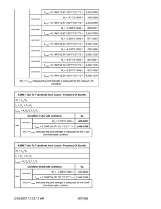


This document provides information on a falling film evaporator vessel including: - The vessel number, customer, designer, date, location, and purchaser. - A nozzle schedule listing 16 nozzles of various sizes and materials including vapor outlets, condensate outlets, spray nozzles, and vents. - Deficiencies noted for the heat exchanger including baffle thickness being less than the minimum required thickness.


