Download as PDF, PPTX
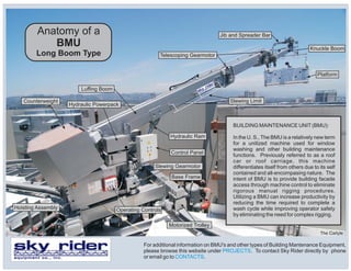
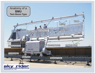

The Building Maintenance Unit (BMU) is a machine used for window washing and building maintenance. It contains components like a base frame, boom, platform, counterweight, and hydraulic systems that allow it to access building facades and move workers safely. Using a BMU increases productivity over manual rigging by reducing wash cycle time and improving operator safety. Key parts include the base frame, hoisting assembly, hydraulic powerpack, boom, and platform.


