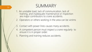
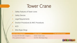
The document outlines the safety requirements, specifications, and operational guidelines for tower cranes, emphasizing the legal standards defined by Indian regulations. Key points include safety features such as limit switches, overload cutoffs, and the importance of regular inspections by competent personnel. Additionally, it discusses the impacts of crane stability, operator training, and maintenance practices on safety performance.


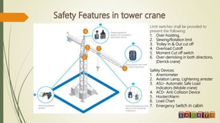
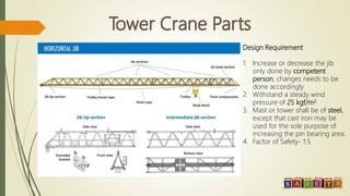
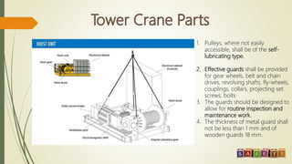
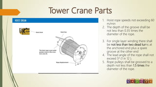
![1. Weight or Over Load limit: - This limit is to safe guard the tower crane from over loading of
the materials.
2. Slewing Limit: - This limit controls the rotation of Main Jib towards one direction [it is set to
trips 11/2 rounds i.e. 360+180 degrees] It prevents the Main supply cable to get twisted/cut
3. Trolley outer Limit/Trolley inner Limit: This limit prevents the trolley travel to the maximum
reach in the main jib.
4. Hook upper Limit: - Restrict the hook Crumple with the trolley.
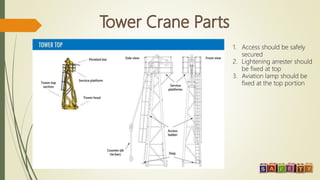
5. Aviation Lamp: - As per the statutory requirement.
6. Lightning Arrestor: - Fixed to avoid Lightning and a separate earthing will be provided.
7. Anemometer: - This shows the wind speed and can restrict the tower crane operation if
any increase in the wind speed.](https://image.slidesharecdn.com/towercranesafety-200522093137/85/Tower-crane-safety-4-320.jpg)