1. SPE-172315-MS
Unique Artificial Lift Solution for Complex Operation in a Caspian Sea
Field Using Jet Pumps
Yunus Berdyev, Dragon Oil plc; Ramy El Habashy, Weatherford Oil Tools
Copyright 2014, Society of Petroleum Engineers
This paper was prepared for presentation at the SPE Annual Caspian Technical Conference and Exhibition held in Astana, Kazakhstan, 12–14 November 2014.
This paper was selected for presentation by an SPE program committee following review of information contained in an abstract submitted by the author(s). Contents
of the paper have not been reviewed by the Society of Petroleum Engineers and are subject to correction by the author(s). The material does not necessarily reflect
any position of the Society of Petroleum Engineers, its officers, or members. Electronic reproduction, distribution, or storage of any part of this paper without the written
consent of the Society of Petroleum Engineers is prohibited. Permission to reproduce in print is restricted to an abstract of not more than 300 words; illustrations may
not be copied. The abstract must contain conspicuous acknowledgment of SPE copyright.
Abstract
Dragon Oil needed to extend the production lifetime for wells with lower than expected natural flow
duration. After reviewing multiple options, Dragon Oil chose to implement artificial lift using jet pumps
to return the candidate wells to the required production levels. This case study highlights the rationale,
implementation, and outcomes from this additional well investment. Candidate wells for jet pump
artificial lifting have been drilled from offshore wellhead platform 1 into the crest of the main reservoir
production basin. A multiwell hydraulic jet pump system was installed during the spring of 2013.
Introduction
Dragon Oil Company’s offshore field is located to the South-West Caspian offshore, the Turkmenistan
portion of South Caspian Basin, in water depths of between 8 and 42 metres. The sandstone and siltstone
formations are the producing reservoirs, with top formations varying from 2100 to 2500 m. The first well
was drilled in 1967, and the first production started in 1978. Platform 1 is a stationary fixed platform
placed on the oil field. A total of 13 wells have been drilled from the platform, five of which are with
complete dual strings, and six are monobore wells. The platform hosts production testing, high and low
pressure gathering systems. Both HP/LP systems transport fluids into available high-pressure intrafield
pipelines with further transfer to manifold platforms. The platform is producing around 5,000 BOPD and
6 MMSCFD, with an average water cut (WC) of 33%.
The desired lift system objectives were:
1. Production rates of 100 to 5,000 BFPD per completion over the entire range of the prospect
reservoir condition.
2. Use the existing completion without the need for a workover rig.
3. Deploy the lift technology using slick-line or coiled tubing services.
4. Use the available space on the platform without a major impact on the infrastructure or platform
activites.
5. Eliminate the need for the weekly wax-cut slick-line intervention and down time.
Selected candidate wells for jet pump artificial lifting have been drilled from offshore wellhead
platform 1 into the crest of the main reservoir production basin. Although the earlier wells drilled from
2. this platform have performed reasonably well with high initial rates and cumulative production, results
from some recent wells were disappointing. Poor results are believed to have been caused by reservoir
heterogeneities and pressure depletion. Moreover, solution gas drive appears to be the dominant mech-
anism for not only oil production but also reservoir pressure; besides, production data indicates major
depletion. Consequently, there existed an urgent need for artificial lifting to revitalize production flow
from the platform’s wells.
Diverse challenges, starting from the reservoir inflow and ending with process production handling,
have posed serious challenges to the project implementation and future expansion. It was imperative to
assess the “do-ability” of this artificial lifting technique, which could have the potential to recover 400
BOPD of additional oil from Platform 1 depleted wells.
Well Performance and ProductionChallenges to Jet Pump Artificial Lifting
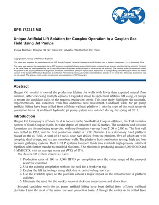
Selected wells X and Z (Figs. 1 and 2) had had production indices ranging from 5 to 7 bpd/psia, which
characterizes them as wells with good production potential: Initial production rates toppled plateau of
1000 BOPD with water cuts varying from 1 to 50%, production GOR varied from 700 scf/bbl to spiking
above 5500 scf/bbl on the depletion natural flow phase.
The selected wells had had a severe wax issue that required slick-line interventions for wax cutting.
Interventions were occurring weekly using 2 2/7-in. wire-type wax scratchers running at depths of 400 m
on average and supported by injecting 15 to 20 L wax inhibitor daily. Although preventive measures have
been taken to control wax deposition, this did not solve the fundamental wax deposition issue. Paraffins
were depositing everywhere in the well production system.
Sand production, though a minor issue (traces have been observed during the course of natural flow
regime of the wells), did not exceed levels of 0.01% of average daily production rates.
Jet Pump Feasibility Application
Various artificial lift methods had been screened and studied within the artificial lifting feasibility
conversion program before selecting the pilot technology for field trial. Among possible solutions
Figure 1—Performance of artificial lifting candidate well X on platform 1 prior to jet pump lifting
2 SPE-172315-MS
3. considered were gas lift and ESP lift methods, but all of them have been postponed for future
consideration.
In addition, the artificial lift feasibility study showed that the hydraulic pumping system would be the
most economical and time saving solution. The jet pump, as the pumping means of artificial lifting
method, employed no moving parts, which could provide longer pump life. The option existed to use
pump internals made of abrasion-resistant material such as tungsten carbide, to minimize wear resulting
from hydraulic lifting. The most important factor in selecting pilot technology was that no workover
interventions were required to convert the well to jet pump lifting.
From all possible jet pumps, the reverse-circulation SSD jet pump installation was selected for the
platform 1 wells because downhole conditions posed significant risks of drawing formation sand along
with the production fluids and potentially filling the well annuli with solids, which would impair well
integrity and operability. Another factor was that the fluids contained appreciable volumes of wax inside
the tubing on the hydraulic lift kicking-off which would have easily plugged the jet pump by bullheading
of the tubing wax into the jet pump internals and the SSD circulation ports. Hence, final jet pump design
applied was the reverse circulation pump principle as shown in Fig. 3.
Jet Pump Operating Principle
Jet pump lifting is referred to as the hydraulic lift class of artificial lifting methods, and its operation
principle is based on achieving the pump lifting action by means of momentum transfer between the power
fluid and wellbore fluid as shown in Fig. 4.
The high-pressure power fluid is injected down the casing, enters through the top of the jet pump, and
passes through the nozzle. The nozzle tip is designed to create the required draw down. Because of the
nozzle shape, the high-pressure, low-speed stream before the nozzle is converted into a low-pressure
high-speed jet. The low-pressure at the nozzle tip pulls on the formation and moves the formation fluids
from the perforations of the producing zone up the well bore, into the downhole jet pump suction to the
nozzle tip. The high-speed jet coming out from the nozzle mixes with the drawn formation fluids in the
Figure 2—Performance of platform 1 artificial lifting candidate well Y prior to jet pummp lifting
SPE-172315-MS 3
4. constant-diameter throat and exits as one “energy
homogenized” stream, still at high speed and low
pressure. That is why the power fluid and formation
fluids stream passes through the diffuser to slow it
down and raise its pressure, enabling it to flow up to
the surface. Then the mixture, at high pressure, is
routed outside the pump through the tubing and
flows up to the surface.
Absence of closely fitted parts allows abrasive
and gassy fluids to be produced. A double-angled
prediffuser reduces cavitation risks and provides
unmatched efficiency. Power-fluid flow parts were
selected to eliminate pressure losses in the annulus
between the tubing circulation valve (SSD) and the
jet pump assembly itself. These parts ensure maxi-
mal system energy efficiency, which results in the
highest rates of controllable fluid drawdown and
reduced operating pressure losses in the system
(Fig. 5).
Hydraulic Jet Pump Surface Facilities
A 300 horsepower diesel-driven power unit (PU) and 600 psi vessel cleaning unit (VCU) were selected
to handle production system requirements across all possible scenarios of production discharge through
the high-pressure and low-pressure surface piping (Fig. 6).
To fit in the available space on the platform, a multiwell, power-fluid-injection manifold was designed
to allow powering up 2 ϩ 1 wells with a single surface equipment package. Two cyclones were used to
handle the sand with each having an installed capacity for processing 0.2% sand volumes from a total
return flow of 5810 B/D with sand grains sized 20 to 110 microns.
The installed surface injection system was used in the commissioning phase because it allowed for
adding service chemicals along with the power fluid to combat numerous production problems such as
paraffin buildup and corrosion to support circulation efficiency. However, when the operating condition
of the system improved, the addition of service chemicals was no longer required.
Furthermore, the suction lines of the power unit are equipped with a two-by-two basket-strainer
filtration skid to protect moving parts of the positive displacement pump from abrasive impairment.
Figure 4—Basic operation diagram of reverse jet pump
Figure 3—Diagram of jet pump hydraulics principle
4 SPE-172315-MS
5. Downhole Jet Pump Design
To begin with, a system sensitivety analysis approach was used to illustrate the relationship between the
inflow performance of the jet pump modeling over the desired range of surface operating horsepower.
Eventually, several throat and nozzle combinations were evaluated to ensure the optimum wellbore
performance. The first phase involved selecting the optimum nozzle/throat combination to achieve the
Figure 5—Temperature profile redistribution due to circulation of hot power fluid
Figure 6—Overview diagram of jet pump surface installation
SPE-172315-MS 5
6. target production rate for each well at the lowest injection pressure, regardless of the power fluid rate per
well.
The second design phase took into account the total power fluid rate required to operate the two wells
together. The nozzle/throat combination was optimized to ensure that selected pumps could meet the
production targets within the capacity of the jet pump surface power unit and the MAASP. The system
analysis curve shown in Figs. 7 and 8 illustrates the modeled well performance with the selected
nozzle/throat combinations in pilot Wells X and Z, respectively.
As a result of the final jet pump modeling analysis, combinations of 11C and 11B were selected for
wells X and Z, respectively, with a total of 200-HP surface power requirements. Reverse-circulation,
downhole jet pumps were adapted and assembled with standard slick-line X-locks to fit in the exisiting
completion SSDs.
Standard slick-line unit and tools were used to open the SSD and to run/pull the downhole jet pump
after running a slick-line gauge cutter and coiled tubing clean-up job.
Production Measurement
The power fluid is injected into the two wells with the designed injection pressure and rate. A flow control
valve controls the power fluid rate and pressure for each well. The power fluid rate for each well is
Figure 7—Jet pump modeling chart for well X
6 SPE-172315-MS
7. measured by a turbine flowmeter. The return fluids, which include power fluid plus the formation fluids
from both wells, are mixed together and routed back to the VCU. Then the power fluid is drawn from the
bottom of the VCU, and the formation flow rate overflows from the top of the VCU to the production line,
where it can be measured by the test separator.
The surface piping system is designed to allow sending all return fluids from any specific well to a test
separator for production measurement. After measurement, the liquids are sent back to the VCU to
maintain its fluid level.
Conclusions and the Future Application
The pilot jet pumps project on offshore platform 1 has revived two depleted wells, thus opening new
horizons for applying the same technology on offshore facilities. Technologically, the system was
designed to service up to five wells from a single surface equipment package to reduce capital cost per
well.
Resolving the wax control issue by means of this system was a major technological achievement. The
intrinsic capability of the surface injection-pumping unit to heat circulation power fluid from 25°C to
47°C at the quintuplex piston of the power unit enabled it to act as a compression block that maintained
the high-temperature rheological properties and avoided all chances of wax depositions inside the well
completion and in both the surface piping and process facilities. The circulation power fluid in the casing
Figure 8—Jet Pump Modeling Chart for Well Z
SPE-172315-MS 7
8. worked as a heat jacket for the tubing string. The power fluid compression block at the pumping unit
added ~0.25°C to the power fluid with each stroke of each plunger (for a total of five plungers). As a
consequence, while passing through the nozzle, the power fluid was further heated by about 10°C with the
wellbore fluids. In an actual well case with wax appearing at temperatures of 28°C to 35°C and the
technological wellhead temperature regime of 47°C, an issue of the well system waxing up was
completely resolved and eliminated. The dragging forces of well fluids velocity had been optimized by
maintaining the kinetic viscosity comparable to reservoir in-situ values of 1 to 2.5 cp. The fluid production
geotherm improved from 0.00203°C/ftHLR on an NFR to 0.00742°C/ftHLR.
The very low operating costs and the OPEX experienced in the pilot pertained mostly to diesel fuel
consumption by the power units, which were driven by internal combustion engines, and by the preventive
maintenance work of those engines, which occurred once in 5 weeks on average.
Plans for the jet pumps project envisage expanding use of the technology in 2014 and 2015 to 14 more
wells on three permanent offshore locations and on one portable jet pump facility and to test the
application in selected offshore locations. Water-cut meters and multi-phase flowmeters are to be installed
on injection and return lines to eliminate manual production measurments.
NOMENCLATURE
BOPD Barrel Oil Per Day
BLPD Barrel Liquid Per Day
GOR Gas Oil Ratio
Scf/bbl Standard Cubic Feet per Barrel
JP Jet Pump
SSD Sliding Side Door
ICE Internal Combustion Engine
PU Power Unit
VCU Vessel Cleaning Unit
MAASP Maximum Allowable Annulus Surface pressure
ACKNOWLEDEMENTS
The authors would like to thank the management of Dragon Oil PLC for granting permission to publish
this paper. We also would like to thank all of the dedicated employees of both Dragon Oil PLC and
Weatherford Oil Tools who contributed to the success of this installation.
We gratefully acknowledge the efforts of Dr. Jaleel Al Khalifah, Emad Buhulaigah, Dr. Mohammed
Hashem, Roberto Espinoza, Dragon Oil PLC; and Toby Pugh, Ahmed BD Shoukry, Weatherford Oil
Tools, for their support during various phases of the project.
REFERENCES
Vogel, J. V. January 1968. Inflow Performance Relationship for Solution Gas Drive Wells, Journal
of Petroleum Technology. 83–93.
Brown, K. E. 1977. The Technology of Artificial Lift Methods. Vol. 1, Petroleum Publishing Company.
Evinger, H. H. and Muskat, M. 1942. Calculation of Theoretical Productivity Factor. Transactions
AIME. 146, 126.
Standing, M. B. 1947. A Pressure-Volume-Temperature Correlation for Mixtures of California Oils
and Gases. In Drilling and Production Practices. API. 275.
Standing, M. B. November 1970. Inflow Performance Relationships for Damaged Wells Producing by
Solution Gas Drive. Journal of Petroleum Technology. 1399–1400.
Coberly, C. J. 1961. Theory and Application of Oil Well Pumps. Kobe Inc.
8 SPE-172315-MS
9. Chew, Ju-Nam. 1959. A Viscosity Correlation for Gas-Saturated Crude Oils. American Institute of
Mining, Metallurgical, and Petroleum Engineers. Vol. 216. 23–25.
Clark, K. M., February 1980. Hydraulic Lift Systems for Low Pressure Wells. Petroleum Engineer
International.
Christ, F. C. and Petrie, H. L. 1989. Obtaining Low Bottomhole Pressures in Deep Wells with
Hydraulic Jet Pumps”, SPE 15177.
Peavy, M. A. and Fahel, R. A. 1991. Artificial Lift with Coiled Tubing for Flow Testing The Monterey
Formation Offshore California., SPE Journal Paper 20024-PA.
Hrachovy, M. J., McConnell, M. L., Damm, M. W., and Wiebe, C. L. 1996. Case History of
Successful Coiled Tubing Conveyed Jet Pump Recompletions Through Existing Completions. SPE
Conference Paper 35586-MS.
Anderson, J.A., Freeman, R.B., and Pugh, T.S. 2005. Hydraulic Jet Pumps Prove Ideally Suited for
Remote Canadian Oilfield”, SPE Conference Paper 94263-MS.
Fraser, Ken and Pugh, Toby. February 2006. Using Jet Pumps to Optimize Single Well Development
Offshore Tunisia. SPE European Artificial Lift Forum.
Pugh, Toby. 2014. Overview of the Hydraulic Pumping System Manual, E-book, first edition.
WWW.iTunes.com.
SPE-172315-MS 9