Third Harmonic Injection Control Method for L-Z-Source Inverter Fed Motor Drive
•
1 like•266 views

Engineer

Recommended
Recommended
More Related Content
What's hot
What's hot (18)
Viewers also liked
Viewers also liked (20)
Similar to Third Harmonic Injection Control Method for L-Z-Source Inverter Fed Motor Drive
Similar to Third Harmonic Injection Control Method for L-Z-Source Inverter Fed Motor Drive (20)
More from IJERD Editor
More from IJERD Editor (20)
Recently uploaded
Recently uploaded (20)
Third Harmonic Injection Control Method for L-Z-Source Inverter Fed Motor Drive
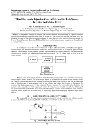
- 1. International Journal of Engineering Research and Development e-ISSN: 2278-067X, p-ISSN: 2278-800X, www.ijerd.com Volume 11, Issue 05 (May 2015), PP.76-81 76 Third Harmonic Injection Control Method for L-Z-Source Inverter Fed Motor Drive Mr. R.Karthikeyan, Mr. K.Balamurugan, M.E Student, Dept. of EEE, St. Michael College of Engg. and Tech.,Kalayarkoil. Assistant professor, Dept. of EEE, St. Michael College of Engg. and Tech.,Kalayarkoil. Abstract:- In this paper it contains the inductor type Z-source inverter, the disadvantage of capacitor charging and discharging can be solved by using diode in the circuit. The inverter can increase the boost factor by changing the value of the different modulation index. By using the third order harmonic injection method the level of the total harmonic distortion (THD) and the losses can be further reduced comparing to the traditional Z-source inverter. I. INTRODUCTION In recent years various Z-Source inverters such as Quasi Z-Source inverter, Switched inductor type Z- Source inverter are presented in numerous diversified field of studies which is focused on application and modeling. The Z-Source inverter contains a Power conversion with buck-boost capabilities. The traditional Z- Source inverter contains two inductors and capacitors respectively. The DC voltage input is given to the Z- source inverter. Fig.1 Block diagram There is some disadvantages present in the traditional Z-source inverter which could be Overcome by inductor type Z-Source inverter. The disadvantages present in the traditional Z-Source inverter such as, during the capacitor charging and discharging the large inrush current flows across the circuit and also the capacitors used in the circuit are of large capacity which is cost effective and reduce the life span of the system. To overcome the disadvantages caused by the traditional Z-source inverter. The proposed inverter eliminates the capacitor in the circuit due to which large inrush current flowing across the circuit is avoided. The efficiency of the proposed inverter can be further more increased. Inductor type Z-source inverter with third order harmonic injection control method can be widely used in engineering applications employing impedance type power inverter. II. INDUCTOR TYPE Z-SOURCE INVERTER The proposed L type Z-source inverter contains no capacitor instead it contains two inductors namely (L1 and L2) and three diodes namely (D1, D2 and D3).the diodes D1,D2 and D3 acts as a switch. Fig.2 Inductor Type Z-Source Inverter
- 2. Third Harmonic Injection Control Method for L-Z-Source Inverter Fed Motor Drive 77 III. OPERATING PRINCIPLES The operating principle of the L type Z- Source inverter is similar to the traditional Z- Source inverter, containing six active states and shoot through zero states. Due to the similar operating principle for the simplified analysis only the shoot through and non-shoot through states are considered. A.NON-SHOOT THROUGH STATE In the non-shoot through state the D1 and D3 are in open position whereas the diode D2 is in closed position. The dc voltage VDC Fig.3 Non-Shoot Through State of Inductor Type Z-Source Inverter Flow across the inductors L1 and L2 and they are connected in series. The inductor L1 and L2 transfer energy from the dc voltage to the inverter circuit. The circuit for non-shoot through state is given in fig. the voltage across the inductors L1 and L2 during non-shoot through state is given by V1N and V2N respectively. dciNN VVVV 21 (1) Therefore the inductors are connected in series the voltage across the inductors L1 and L2 are similar. NN VV 21 (2) From the equation (1) and (2) the voltage across the inductors L1 and L2 are given by, idcN VVV 2 1 2 1 1 (3) idcN VVV 2 1 2 1 2 (4) Where Vdc is the DC source voltage; Vi is the dc link voltage. B. SHOOT THROUGH STATE The Shoot through state occurs when both the switch of the upper or lower leg thyristors of any phase leg gets shorted. During the shoot through state the diodes D1 and D3 are in closed position whereas diode D2 is in open position. The inductors L1 and L2 are connected in parallel which stores the energy. Fig.4 Shoot through State of Inductor Type Z-Source Inverter The circuit for shoot through state is given in fig. The dc voltage flow across the inductors L1 and L2 are given by V1S and V2S respectively. dcSS VVV 21 (5) Applying volt-second balance principle to the inductors L1 and L2 we get, dci V D D V 1 1 (6)
- 3. Third Harmonic Injection Control Method for L-Z-Source Inverter Fed Motor Drive 78 D D B 1 1 (7) Where B is the boost factor; D is shoot-through duty cycle. IV. EXTENDED INDUCTOR TYPE Z-SOURCE NETWORK The extended inductor type Z-source network can improve the voltage gain. By Fig.5 Extended Inductor Type Z-Source Network Increasing the number of inductors and diodes in the network the boost factor can be improved. A.NON-SHOOT THROUGH STATE In the non-shoot through state the diodes such as D1,1 ,D1,3 ,D2,1 ,D2,3,…………Dn-1,1 ,Dn-1,3 are kept in open condition. Whereas the diodes such as D1,2 ,D2,2 ,…………Dn-1,2 are in closed conditions. The Fig.6 Non-Shoot through State of Extended Inductor Type Z-Source Network Dc voltage flow across the inductors such as L1,L2,…….Ln-1 and Ln and they are connected in series. The inductor L1,L2,Ln-1 and Ln transfer energy from the dc voltage to the inverter circuit. The circuit for non- shoot through state is given in fig. the voltage across the inductors L1,L2,…….Ln-1 and Ln during non-shoot through state is given by V1N,V2N,………V(n-1)N and V(n)N respectively. dciNnNnNN VVVVVV )()1(21 (8) Therefore the inductors are connected in series the voltage across the inductors L1,L2,…...,Ln-1 and Ln are similar. NnNnNN VVVV )()1(21 (9) Where Vdc is the DC source voltage; Vi is the dc link voltage. B. SHOOT THROUGH STATE The Shoot through state occurs when both the switch of the upper or lower leg thyristors of any phase leg gets shorted. During the shoot through state the diodes D1,2 ,D2,2 ,………Dn-1,2 are in open conditions. Fig.7 Shoot through State of Extended Inductor Type Z-Source Network
- 4. Third Harmonic Injection Control Method for L-Z-Source Inverter Fed Motor Drive 79 whereas diodes D1,1 ,D1,3 ,D2,1 ,D2,3,…………Dn-1,1 ,Dn-1,3 is in closed position. The inductors L1, L2,…..., Ln-1 and Ln are connected in parallel which stores the energy. The circuit for shoot through state is given in fig. The dc voltage flow across the inductors L1, L2,…..., Ln-1 and Ln are given by V1S, V2S,……,V(n-1)S and V(n)S respectively. dcSnSnSS VVVVV )()1(21 (10) Applying volt-second balance principle to the inductors L1, L2,…..., Ln-1 and Ln we get, D Dn B 1 )1(1 (11) Where B is the boost factor; D is shoot-through duty cycle. When n=2, D D B 1 1 (12) When n=1, D B 1 1 (13) The range of D is [0,1). The boost factor of the inductor type Z-Source inverter can be improved by increasing the number of inductor. V. THIRD ORDER HARMONIC INJECTION CONTROL METHOD The third order harmonic injection control method have an advantage that the modulation index can be increased and also the overshoot period can be maintained constant and variable. If only third order harmonic is injected Vr is given by, ttVr sin19.0sin15.1 (18) In third order harmonic injection constant boost technique the reference sinusoidal signal is merged with third harmonic sinusoidal waveforms with one third amplitude of the fundamental, to generate non- sinusoidal waveforms. Constant shoot-through is provided in zero states by comparing the triangular carrier wave with a positive, negative and constant magnitude and Generate non-sinusoidal reference waveforms. The variable shoot-Through are provided considering the third harmonic injected sinusoidal reference wave and triangular carrier wave. VI. SIMULATION A.SIMULATION CIRCUIT The figure shows the proposed circuit containing inductor type Z-source inverter with third order harmonic Fig 8.simulation circuit injection control method. B.INPUT VOLTAGE AND CURRENT The input DC voltage of about 230V is given as input to the L-Z-source inverter circuit.
- 5. Third Harmonic Injection Control Method for L-Z-Source Inverter Fed Motor Drive 80 Fig 9. Input voltage and current C.TRIGGERING PULSES The switching frequency is about 2.5 KHz. Fig 10. Triggering pulses D. SIMULATION OUTPUT The simulation output three phase voltage of magnitude 700V and current of 10A is obtained. Fig.11 Simulation Output voltage Fig.12 Current E.THD ANALYSIS As number of cycles increase the harmonic level will decreased the measured voltage and THD is Minimum.
- 6. Third Harmonic Injection Control Method for L-Z-Source Inverter Fed Motor Drive 81 Fig.13 THD Analysis VII. CONCLUSION The simulation of the Inductor type Z-source inverter with third order harmonic injection control method is carried. The output voltage and current of the inverter circuit is given. The output across the inverter and the voltage and current given to the induction motor can be controlled by using third order injection control method. From the simulation analysis Inductor type Z-source inverter with third order harmonic injection control method can be widely used in engineering applications employing impedance type power inverter. REFERENCES [1]. Byamakesh Nayak, Saswati Swapna Dash “Performance Analysis of Different Control Strategies in a Z-source Inverter” Engineering, Technology & Applied Science Research Vol. 3, No. 2, 2013. [2]. Lei Pan “L-Z- Source Inverter” IEEE Trans. Power Electronics, 10.1109/ TPEL.2014. [3]. F. Z. Peng; , “Z-source inverter,” IEEE Trans. Ind. Appl., vol. 39, no. 2, pp. 504-510, Apr. 2003. [4]. Gajanayake, C.J. ; Fang Lin Luo; Hoay Beng Gooi; Ping Lam So; Lip Kian Siow; , “Extended boost Z- source inverters,” IEEE Trans. Power Electron., vol. 25, no. 10, pp. 2642-2652, Oct. 2010. [5]. Miao Zhu; Kun Yu; Fang Lin Luo; , "Switched Inductor Z-Source Inverter," Power Electronics, IEEE Transactions on, vol.25, no.8, pp. 2150- 2158, Aug. 2010.