Download to read offline
![Mahmud Al-Naser et al Int. Journal of Engineering Research and Applications www.ijera.com
ISSN : 2248-9622, Vol. 4, Issue 5( Version 6), May 2014, pp.01-07
www.ijera.com 1 | P a g e
BER Performance of a Vector Antenna Array versus a Uniform
Linear In a Multipath Fading Channel
Mahmud Al-Naser, Nizar J Ahmad, Salem Salamah
Dept. of Electronic Engineering Technology, Public Authority Of Applied Education And Training, AlShuwaik,
Kuwait
Dept. of Electronic Engineering Technology, Public Authority Of Applied Education And Training, AlShuwaik,
Kuwait
Dept. of Electronic Engineering Technology, Public Authority Of Applied Education And Training, AlShuwaik,
Kuwait
ABSTRACT
In multipath environments, the transmitted signal polarization is affected by channel fading which results in a
multipath polarized signal component on the receiver side. These receivers usually employ single polarized
uniform linear antenna array (ULA) which measure one component of the received electromagnetic (EM)
signal. In rich scattering environments, however, it may be possible to improve the performance by using
“vector antennas”, as they can detect up to six independent components of the EM field. In this paper, we
consider the advantage of vector antenna (VA) over uniform linear array (ULA) receiver for code-division
multiple-access (CDMA) signals in a multiuser environment. We consider a closed loop power control (CLPC)
for a beamformer-RAKE receiver for wireless CDMA multiuser system. The performance enhancement in Bit
Error Rate (BER) is investigated for matched-filter receivers using various VA’s and ULA for a fading
multipath channel. Analysis, theoretical curves, and simulations of VA and ULA receivers suggest that VA can
better exploit multipath and therefore significantly improve the diversity gain and bit-error-rate performance of
CDMA signals in the presence of a frequency selective rich multipath channel.
Keywords— code-division multiple-access , multipath channels, polarization diversity , receiver diversity ,
power control.
I. Introduction
In recent years, the number of users for
wireless services such as internet and video have
rapidly increased where providers of these services
are required to deploy systems with higher data rates,
combat fading and reduce interference thus
provides higher quality of service. The space- time
system, that employ multiple antennas at transmitter
or receivers aim to exploits channel characteristics
and provide diversity gain. Such systems employ
uniform linear antenna array to respond to the
vertical or horizontal polarization component of the
EM field [1]. Extensions of these antenna array to
dual-polarized antenna array have been considered in
conjunction with multiuser detection in[2] where the
diversity gain obtain is due to the effect of space and
polarization systems used. Most of research have
focused on developing an algorithms at both ends of
the communication systems to enhance performance
by using antenna arrays technology and multiuser
receivers to com-bat fading and reduce correlation
between users in order to lower error probability and
therefore obtain a higher quality of received signal.
Since the signal consists of six field
component (three electric and three magnetic), some
potentially useful information may be neglected.
Andrews et al [3] has suggested that dramatic gains
in wireless capacity might be possible by exploiting
these extra components of the received signal. In
principle, a “Vector antenna” can independently
detector excite all six EM field components enabling
the com-the communication system to access an
additional signaling dimensions, which may enhance
performance in the same way as antenna arrays [1].
These extra dimensions can provide additional
diversity to combat signal fading, allow the system to
spatially leverage bandwidth by transmitting multiple
separable signals in the same bandwidth, and
improve the suppression of interference in multiuser
environment.
A “tripole” antenna that consists of three
mutually-orthogonal dipoles by Andrew have shown
through simulation, that this antenna improves on the
capacity of scalar and dual-polarized antennas for a
simple propagation ex-ample involving a line-of-
sight component and one reflected path. A similar
study of a three-element antenna system consisting of
a loop and two dipoles was presented in [4] where
coupling between antenna elements and return loss
was investigated. In [5], Konanur et al has shown an
in-crease of capacity of vector antennas relative to a
linear ar-ray antenna. Also, tripole antennas have
RESEARCH ARTICLE OPEN ACCESS](https://image.slidesharecdn.com/a045060107-140710235433-phpapp01/85/A045060107-1-320.jpg)
![Mahmud Al-Naser et al Int. Journal of Engineering Research and Applications www.ijera.com
ISSN : 2248-9622, Vol. 4, Issue 5( Version 6), May 2014, pp.01-07
www.ijera.com 1 | P a g e
BER Performance of a Vector Antenna Array versus a Uniform
Linear In a Multipath Fading Channel
Mahmud Al-Naser, Nizar J Ahmad, Salem Salamah
Dept. of Electronic Engineering Technology, Public Authority Of Applied Education And Training, AlShuwaik,
Kuwait
Dept. of Electronic Engineering Technology, Public Authority Of Applied Education And Training, AlShuwaik,
Kuwait
Dept. of Electronic Engineering Technology, Public Authority Of Applied Education And Training, AlShuwaik,
Kuwait
ABSTRACT
In multipath environments, the transmitted signal polarization is affected by channel fading which results in a
multipath polarized signal component on the receiver side. These receivers usually employ single polarized
uniform linear antenna array (ULA) which measure one component of the received electromagnetic (EM)
signal. In rich scattering environments, however, it may be possible to improve the performance by using
“vector antennas”, as they can detect up to six independent components of the EM field. In this paper, we
consider the advantage of vector antenna (VA) over uniform linear array (ULA) receiver for code-division
multiple-access (CDMA) signals in a multiuser environment. We consider a closed loop power control (CLPC)
for a beamformer-RAKE receiver for wireless CDMA multiuser system. The performance enhancement in Bit
Error Rate (BER) is investigated for matched-filter receivers using various VA’s and ULA for a fading
multipath channel. Analysis, theoretical curves, and simulations of VA and ULA receivers suggest that VA can
better exploit multipath and therefore significantly improve the diversity gain and bit-error-rate performance of
CDMA signals in the presence of a frequency selective rich multipath channel.
Keywords— code-division multiple-access , multipath channels, polarization diversity , receiver diversity ,
power control.
I. Introduction
In recent years, the number of users for
wireless services such as internet and video have
rapidly increased where providers of these services
are required to deploy systems with higher data rates,
combat fading and reduce interference thus
provides higher quality of service. The space- time
system, that employ multiple antennas at transmitter
or receivers aim to exploits channel characteristics
and provide diversity gain. Such systems employ
uniform linear antenna array to respond to the
vertical or horizontal polarization component of the
EM field [1]. Extensions of these antenna array to
dual-polarized antenna array have been considered in
conjunction with multiuser detection in[2] where the
diversity gain obtain is due to the effect of space and
polarization systems used. Most of research have
focused on developing an algorithms at both ends of
the communication systems to enhance performance
by using antenna arrays technology and multiuser
receivers to com-bat fading and reduce correlation
between users in order to lower error probability and
therefore obtain a higher quality of received signal.
Since the signal consists of six field
component (three electric and three magnetic), some
potentially useful information may be neglected.
Andrews et al [3] has suggested that dramatic gains
in wireless capacity might be possible by exploiting
these extra components of the received signal. In
principle, a “Vector antenna” can independently
detector excite all six EM field components enabling
the com-the communication system to access an
additional signaling dimensions, which may enhance
performance in the same way as antenna arrays [1].
These extra dimensions can provide additional
diversity to combat signal fading, allow the system to
spatially leverage bandwidth by transmitting multiple
separable signals in the same bandwidth, and
improve the suppression of interference in multiuser
environment.
A “tripole” antenna that consists of three
mutually-orthogonal dipoles by Andrew have shown
through simulation, that this antenna improves on the
capacity of scalar and dual-polarized antennas for a
simple propagation ex-ample involving a line-of-
sight component and one reflected path. A similar
study of a three-element antenna system consisting of
a loop and two dipoles was presented in [4] where
coupling between antenna elements and return loss
was investigated. In [5], Konanur et al has shown an
in-crease of capacity of vector antennas relative to a
linear ar-ray antenna. Also, tripole antennas have
RESEARCH ARTICLE OPEN ACCESS](https://image.slidesharecdn.com/a045060107-140710235433-phpapp01/75/A045060107-1-2048.jpg)
![Mahmud Al-Naser et al Int. Journal of Engineering Research and Applications www.ijera.com
ISSN : 2248-9622, Vol. 4, Issue 5( Version 6), May 2014, pp.01-07
www.ijera.com 2 | P a g e
been investigated for a different number of receivers
in frequency selective multipath Rayleigh fading
channels for code division multiple access CDMA
system [6].
In cellular communication system, it is
known that the CDMA system is interference limited.
In the uplink from mobile to base station, multiple
access interference (MAI)due to multipath fading and
cross correlation between users, results in power
variation of the signal level betweenusers located at
different distances from base station. This is known
as near-far effect [7]. As a result of this, MAI de-
creases the received signal level and therefore
reduces sig-nal quality. This in turn limits the
capacity of the CDMA system. One way to overcome
the effect of interference is by monitoring the signal
power and maintaining an accept-able level of signal-
to-interference plus-noise ratio (SINR) by increasing
or decreasing the transmitted power known as power
control. In the last two decades, a lot of research has
been devoted to different power control schemes. In
the research study by Zander [8], Grandhi [9] and
Foschini and Miljanic [10], power control has been
applied in a centralized or distributed way. For
systems that employ antenna array, a joint power
control and beamforming was investigated for linear
antenna system in a multiuser environment [11].
Similarly, to further reduce interference and increase
capacity, multiuser detection was investigated in
addition to the joint power control and beamforming
[12].
In this paper, we will study the performance
and investigate diversity gain of antenna array
receivers that employ CLPC to mitigate near-far
effect in multiuser environment over Rayleigh fading
channel. Two systems of antennas are studied: the
ULA and the Vector antennas receivers. The antenna
array is employed at the base station and the up-link
situation is considered here. The CLPC is used for a
different number of vector antenna systems in
frequency selective multipath fading channel. We
will evaluate the performance of the CDMA system
with vector antenna as a function of Bit Error Rate
(BER) for different propagation conditions.
The organization of this paper is as follows:
in section II, we will propose the system model
where the channel model and receiver using closed-
loop power- control (CLPC) is presented. In section
III, SINR calculation for RAKE receiver and
theoretical results for SINR and BER is introduced.
In section IV, simulation results are presented and
finally a conclusion is drawn.
II. System Model
In this work, we will consider the
application of antenna array system in uplink
condition for n users and a single base station. We
assume a BPSK modulation scheme for direct
sequence synchronous code division multiple
access(DS-CDMA) system to be used.
Consider a single vector antenna at the
receiver. Each arriving multipath component is a
two-dimensional vector R(t), consisting of
horizontally and vertically polarized components of
the electric field. For narrowband sinusoidal signals,
it is convenient to write the signal in terms of its
complex envelope Z, where R(t) = Re{exp(jωc t)Z},
and ωc is the carrier frequency. For any polarized
signal, the complex envelope can be written as
sin
cos
cossin-
sincos
ej
j
AZ , (1)
where A, ψ, α, β are the amplitude, phase, orientation
angle, and ellipticity angle, respectively [13]. Since
the signal is a function of the transmitted data, the
amplitude, phase and polarization angles vary with
time, and we write Z = Z(t). If the multipath
component is reflected or scattered by an object in the
far-field, then the signal can be approximated as a
plane wave at the receiver. Let E(t) and H(t) de-note
the three-dimensional complex envelopes of the
electric and magnetic field vectors respectively at the
receiver, and suppose that the multipath component
arrives at the sensor from the direction 𝒖 𝒓 , where
𝒖 𝒓 =
𝐜𝐨𝐬 𝜽 𝐬𝐢𝐧 𝝋
𝐬𝐢𝐧 𝜽 𝐬𝐢𝐧 𝝋
𝐜𝐨𝐬 𝝋
(2)
where θ and υ are the azimuth and elevation,
respectively, of the incoming signal in the receiver
coordinates (see Fig. in [6]). For a narrowband plane
wave propagating in a non conductive, homogeneous,
and isotropic medium, the received signal can be
modeled by [13]
𝐘 𝑡 =
𝐄 𝐭
η𝐇(𝐭)
= 𝐵(𝜃, 𝛼) 𝐙 𝑡 + 𝐧(𝑡) (3)
where n(t) represents thermal noise, η is the intrinsic
impedance of the propagation medium, and
𝐵 𝜃, 𝜑 =
− sin 𝜃 cos 𝜃 cos 𝜑
cos 𝜃 sin 𝜃 cos 𝜑
0 − sin 𝜑
sin 𝜃 cos 𝜑 sin 𝜃
sin 𝜃 cos 𝜑 − cos 𝜃
− sin 𝜑 0
. (4)
We are interested in using the antenna
system described above to detect CDMA signals in
the presence of rich multipath and multiuser system.
The transmitted signal of user i is a complex base
band signal of the form
𝑆𝑖 = 𝑏𝑖 𝑚 𝑐𝑖(𝑡 − 𝑚𝑇)𝑀
𝑚=1 (5)](https://image.slidesharecdn.com/a045060107-140710235433-phpapp01/85/A045060107-2-320.jpg)
![Mahmud Al-Naser et al Int. Journal of Engineering Research and Applications www.ijera.com
ISSN : 2248-9622, Vol. 4, Issue 5( Version 6), May 2014, pp.01-07
www.ijera.com 3 | P a g e
where ci (t) is a unit-energy spreading waveform that
vanishes outside the interval [0, T), and bi is a
sequence of transmitted information bits for user i.
When Si (t) is transmitted, the horizontally and
vertically polarized components of each multipath
component consist of Si (t) with some amplitude and
phase shift, so that Zi (t) = Zi Si (t) for some fixed
complex vector Zi .
We assume that each user’s transmitted
signal propagates to the receiver by multiple paths
produced by L different scatterers. If the ℓ-th path for
user i arrives at the receiver from direction
𝜃𝑖,ℓ , 𝜑𝑖,ℓ , the superposition of the multipaths of all
n users and noise at the receiver is given by
𝒀 𝑡 = 𝑃𝑖
𝐿
ℓ=1
𝑛
𝑖=1 𝐵 𝜃𝑖,ℓ , 𝜑𝑖,ℓ 𝐙𝑖,ℓ 𝑆𝑖 𝑡 − 𝜏𝑖,ℓ +
𝐧(𝑡) (6)
here Pi is the signal power of the i-th user, 𝐵 𝜃 , 𝜑 is
the6 × 2 antenna response given in eq. 4, τi,ℓ is the
propagation delay of the ℓ-th path of user i, and Zi,ℓ
reflects the change in amplitude, phase, and
polarization experienced by the ℓ-th multipath
component as it propagates from the transmitter of
user i to the receiver. The noise n(t) is a zero-mean
complex Gaussian vector with covariance σ2
I.
A tem-element vector antenna with tem ≤ 6 can sense
only tem components of Y(t). The received signal in
eq. 2 above can be re-written as
𝐘 𝑡 = 𝑃𝑖
𝐿
ℓ
𝑛
𝑖=1 𝐆𝑖,ℓ 𝑆𝑖 𝑡 − 𝜏𝑖,ℓ + 𝐧(𝑡), (7)
where 𝐆𝑖,ℓ consists of the appropriate tem
components of 𝐵 𝜃𝑖,ℓ , 𝜑𝑖,ℓ 𝐙𝑖,ℓ, . The components of
the vector 𝐙𝑖,ℓ are modeled as i.i.d. zero-mean
complex Gaussian random variables and therefore the
elements of 𝐆𝑖,ℓ are also zero-mean complex
Gaussian random variables.
Assuming we know the channel coefficients,
delay spread and user’s spreading waveforms at the
receiver, we can write the post-correlation signal of
the first user for the m-th bit and ℓ-th multipath as
𝐘1,ℓ 𝑚 = 𝑐1
∗
(𝑡 −
𝑚𝑇 +𝜏1,ℓ
𝑚−1 𝑇+𝜏1,ℓ
𝑚𝑇
+ 𝜏1,ℓ) 𝐘 𝑡 𝑑𝑡
= 𝑃1 𝐆1,ℓ 𝑏1 𝑚 + 𝐢1,ℓ + 𝐧1,ℓ , (8)
where c1 (t − τ1,ℓ ) is the spreading code of the first
user delayed by τ1,ℓ , b1 (m) is the m-th data bit for
the first user, and n1,ℓ, is the thermal noise.
This model is also easily generalized to
arrays that consist of multiple spatially-separated,
non-interacting vector antennas. Suppose that the
receive array consists of r spatially-separated vector
antennas located at positions x1 , . . . , xr in receiver
coordinates, that Yi(t) is the signal detected at the i-th
receiver antenna, and that
𝐘 t =
𝐘1 𝑡
⋮
𝐘𝑟(𝑡)
(9)
A simple model for the resulting space-polarimetric
channel is given with 𝐆ℓ = [ 𝐴 𝑟 𝜃, 𝜑 ⊗
𝐵 𝜃, 𝜑 ]𝑍ℓ , where
𝐵𝑟 𝜃, 𝜑 = 𝐴 𝑟 𝜃, 𝜑 ⊗ 𝐵 𝜃, 𝜑 , (10)
⊗ is the Kronecker product, 𝐴 𝑟 𝜃, 𝜑 is the
classical narrow band array response
𝐴 𝑟 𝜃, 𝜑 =
exp −𝑗𝑤𝑐 𝑑1
.
.
.
exp −𝑗𝑤𝑐 𝑑 𝑟
, 𝑑𝑖 = −
𝑢 𝑟 . 𝑥 𝑖
𝑐
(11)
and c denotes the speed of light.
III. MAI and SINR Calculation
The multiple-access interference (MAI)
contributed from other users and self-interference is
given by
𝐢1,ℓ = 𝑃1 𝐆1,𝑘 𝐈1,ℓ,1,𝑘
𝐿
𝑘=1,𝑘≠ℓ
+ 𝑃𝑖 𝐆𝑖,𝑘 𝐼1,ℓ,𝑖,𝑘
𝐿
𝑘=1
𝑛
𝑖=2 (12)
where the first term corresponds to self-interference
due to multipath, and the second term is due to
multiple-access interference (MAI) and
𝐈1,ℓ,1,𝑘 = 𝑏𝑖 𝑐𝑖
∗
(𝑡 −
𝑚𝑇 +𝜏1,ℓ
𝑚−1 𝑇+𝜏1,ℓ
𝑚𝑇 + 𝜏𝑖,𝑘)
𝑐1
∗
𝑡 − 𝑚𝑇 + 𝜏1,ℓ 𝑑𝑡 (13)
If we denote the total undesired interference
as 𝐧1,ℓ = 𝐢1,ℓ + 𝐧1,ℓ , then the correlation matrix can
be written as
𝐑 𝐧 𝐧,1,ℓ = 𝑃1 𝐆1,𝑘 𝐆1,𝑘
∗
𝐿
𝑘=1,𝑘≠ℓ
+ 𝑃𝑖 𝜌1,𝑖 𝐆𝑖,𝑘 + 𝜍𝑛
2𝐿
𝑘=1
𝑛
𝑖=2 I (14)
where 𝜌1,𝑖 is the correlation factor of spreading
sequence between first user and user i.
If the weight vector of the desired user for ℓ
path is given by 𝑤1,ℓ , then the output of the
beamformer of the space-time RAKE receiver for
path is given as](https://image.slidesharecdn.com/a045060107-140710235433-phpapp01/85/A045060107-3-320.jpg)
![Mahmud Al-Naser et al Int. Journal of Engineering Research and Applications www.ijera.com
ISSN : 2248-9622, Vol. 4, Issue 5( Version 6), May 2014, pp.01-07
www.ijera.com 4 | P a g e
𝑧1,ℓ 𝑚 = 𝑤1,ℓ
∗
𝐘1,ℓ 𝑚 = 𝑃1 𝑤1,ℓ
∗
𝐆1,ℓ 𝑏 𝑚
+ 𝑤1,ℓ
∗
𝐧1,ℓ . (15)
Where the optimum weight of the
beamformer that maximizes the signal-to-
interference-plus-noise ratio (SINR) is given by [14]
𝑤1,ℓ
∗
= 𝐑nn,1,ℓ
−1
𝐆1,ℓ , (16)
For maximal ratio combining (MRC), the
decision statistic is given as scalar output
𝑏 = 𝑠𝑔𝑛 𝑧1,ℓ(𝑚)𝐿
ℓ=1 (17)
For closed loop power control, we compare
γ for the desired user to a threshold γth and the
performance is determined by SINR. The SINR after
RAKE combining defined as Post-RAKE, the SINR
for ℓ path is given by
𝛾1,ℓ =
𝑃1 𝑤1,ℓ
∗
𝐆1,ℓ
2
𝑤1,ℓ
∗
𝐧
2
=
𝑃1 𝑤1,ℓ
∗
𝐆1,ℓ 𝐆1,ℓ
∗
𝑤1,ℓ
𝑃𝑖 𝜌1,𝑖 𝑤1,ℓ
∗
𝐆𝑖,ℓ 𝐆𝑖,ℓ
∗
𝑤1,ℓ + 𝜍𝑛
2𝐿
ℓ=1
𝑁
𝑖=2
=
𝑃1 𝑤1,ℓ
∗
𝐆1,ℓ 𝐆1,ℓ
∗
𝑤1,ℓ
𝑤1,ℓ
∗ 𝐑 𝑛 𝑛1,ℓ 𝑤1,ℓ
. (18)
And the total SINR after RAKE combining is given
𝛾_𝑏 = _(𝑙 =
1)^𝐿▒〖 𝛾_(1, 𝑙) 〗 (19)
If the noise is white (Rn = σ2
I) and Gℓ is a zero-mean
complex Gaussian random variable, then γb has χ2
probability density function(pdf) with 4L degrees of
freedom [16]:
𝑓𝛾 𝑏
𝛾 =
𝛾2𝐿−1
𝛾 2𝐿 2𝐿−1 !
𝑒
−𝛾
𝛾 (20)
where 𝛾 =
𝜌
𝐿 𝜍2 is the average SNR-per-path-per-
antenna. The average BER of BPSK modulation is
therefore given by proakis [16]
𝑃𝑏 = 𝑄 2𝛾
∞
0
𝑓𝛾 𝑏
𝛾 𝑑𝛾
=
1−𝑢
2
2𝐿
2𝐿−1+ℓ
ℓ
2𝐿−1
ℓ=0
1+𝑢
2
ℓ
(21)
where for the tripole antenna
𝑢 =
𝛾
1 + 𝛾
And for six element vector antennas
𝑢 =
2𝛾
1 + 2𝛾
The difference between the γ and γth is
compared and the error command e = γ − γth is
evaluated. Then a power control command bit is sent
to increase or decrease transmitted power for next
sampling period Tp bits by ∆p increment. We can
summarize the CLPC as follows
𝑃 𝑖 + 1 = 𝑃 𝑖 − 𝑒 𝑖 ∆𝑝 (22)
Where,
PC bit = sign[e(i)]=
−1, 𝑒 𝑖 < 0
+1 , 𝑒 𝑖 > 0
(23)
To compare the performance of the vector-
antenna array to a uniform linear array (ULA), we
present the equivalent ULA model. The ULA [15] is
modeled as a collection of dipole antenna elements
that are spatially and uniformly distributed in a plane
containing array elements. The antenna response for
a uniform linear array parallel to the z-axis and
centered on the x-axis can be modeled as
𝐵 𝜃, 𝜑 = sin 𝜑
𝑒
−𝑗2𝜋𝑥1 cos 𝜃
𝜆 0
.
.
.
𝑒
−𝑗2𝜋𝑥 𝑀 cos 𝜃
𝜆 0
(24)
where 𝑥 𝑖 , i = 1, 2, . . . , M corresponds to the x-
coordinates of the antennas. This uniform antenna
system can respond to one polarization component,
horizontal or vertical.
IV. Simulation
In this section we numerically plot the BER
of the matched filter (MF) receiver for vector and
ULA antennas. We consider a single base station and
the uplink from mobile users to the base station,
where all users transmit to the same base station. In
these simulations, we consider uniform linear arrays
and vector antennas that consist of tem = 2,3,6
elements implemented at the base station which
applies CLPC scheme in a multipath environment.
We assume that the multipath components
of the desired and interference signals are uniformly
distributed on a sphere where the azimuth angle θi,ℓ,
are i.i.d. and uniform on [0, 2π], and the elevation
angles υi,ℓ, are i.i.d. with probability density function
𝑃 𝜑𝑖,ℓ =
1
2
sin 𝜑𝑖,ℓ , 0 < 𝜑𝑖,ℓ < 𝜋
0, otherwise
(25)](https://image.slidesharecdn.com/a045060107-140710235433-phpapp01/85/A045060107-4-320.jpg)
![Mahmud Al-Naser et al Int. Journal of Engineering Research and Applications www.ijera.com
ISSN : 2248-9622, Vol. 4, Issue 5( Version 6), May 2014, pp.01-07
www.ijera.com 5 | P a g e
and the polarizations Zi, are i.i.d. CN (0, I). The noise
n(t) is spatially and temporally white and Gaussian
(i.e. E[n(t)n†
(t + τ )] = σ2
I). The channel is assumed
to be a frequency-selective, slowly Rayleigh fading,
and the multipath delays τ are set at discrete intervals,
which is equivalent to one chip duration (Tc). The
scenario of synchronous users is assumed here. The
number and values of the multipath delays L are
equal for all users at the receiver and we assume the
detection of the first user.
In all of our simulation we consider L = 2
multipath components with delays τ1 and τ2,
respectively, such that τ2 is delayed by one chip
relative to τ1 . At the transmitter we assume BPSK
modulation and Gold spreading sequences of length
31 [17] and a unit-energy spreading waveform. The
SINR threshold γth for the CLPC is considered for the
desired user where other users are set to a fixed γ
value that is equal to target γth .The 3-element tripole
antenna proposed by Andrews et al consists of three
mutually orthogonal dipoles, where 𝐵 𝜃ℓ, 𝜑ℓ are given
by
𝐵 𝜃ℓ, 𝜑ℓ =
− sin 𝜃ℓ cos 𝜃ℓ cos 𝜑ℓ
cos 𝜃ℓ sin 𝜃ℓ cos 𝜑ℓ
0 − sin 𝜑ℓ
(26)
where the first two component in above matrix
correspond to the dual antenna case. The 3-element
vector antenna proposed by Konanur et al [4] which
consists of two dipoles and a loop , where the
elements of 𝐵 𝜃ℓ, 𝜑ℓ are given by
𝐵 𝜃ℓ, 𝜑ℓ =
− sin 𝜃ℓ cos 𝜃ℓ cos 𝜑ℓ
cos 𝜃ℓ sin 𝜃ℓ cos 𝜑ℓ
cos 𝜃ℓ cos 𝜑ℓ sin 𝜃ℓ
(27)
for the ULA, we will use the model presented in eq.
24, that consist of up to 6 antenna elements.
The VA array will be consisting of the same
number of elements. For example, the array of tripole
VA will consist of tripole antennas displaced at
distance d from each other and the same is true for
different VA elements.
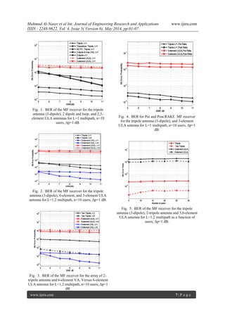
In Fig. 1 the performance of MF detector for
desired user is plotted for three types of antenna
configuration: 2,3-element ULA, dual and single
tripole antenna ,and two dipole and a loop proposed
by Kananor at a number of γth values and n=10 users.
The performance in terms of the BER of CLPC with
step size of 1 dB is assumed. The figure shows that
VA performance improve as we go from dual to
tripole and gain much higher diversity compared to
ULA. The tripole antenna is more effective in
mitigating interference as we compare to other
antenna configuration in this figure.
In Fig. 2, simulation for 3-element ULA and
VA antenna for L = 1, 2 multipath and n=10 users is
plotted. We notice that tripole antenna outperforms
the ULA and maintain this performance gain over L
= 1, 2 multipath components. Due to the high
interference from multiuser and multipath channels,
the ULA have a marginal improvement in BER.
Increasing number of VA elements from 3 to 6 result
in much lower BER than tripole antenna case. Fig. 3
is plotted for ULA with 6-element antenna and
compared to an array of two tripole antenna and 6-
element vector antennas. Comparing the BER
attained for VA and ULA, we notice that at higher
SNR values and L = 2 multipath, both VA array and
6-element VA have gained diversity while ULA is
approaching error floor. This shows that VA can
better exploit multipath environment and can benefit
from space diversity and power control more than
ULA.
In Fig. 4, the performance of Pre and Post
Rake are plotted for ULA and VA antennas. Since
interference is higher at Pre Rake than Post Rake
combining, therefore a lower BER obtained at Post
Rake. In both cases of VA and ULA, the
improvement in BER seems to be approximately
equivalent.
Fig. 5 shows the eff ect of BER as a function
of the number of users. In the ULA case, the benefit
of increasing number of antennas have slight impact
on performance and therefore BER. On the other
hand, VA has shown significant improvement when
we went from single tripole to an array of two tripole
case, therefore, the BER for the number of users that
is accommodated is much lower than in VA systems.
V. Conclusions
Performance of VA and ULA with CLPC
have been analyzed in both multipath and multiuser
environment. At the receiver side, we have studied
MF receiver employing vector antennas and ULA
with CLPC. The assumption of equivalent SINR for
the interference and threshold value is assumed in
order to study the ability of proposed VA and ULA in
mitigating interference. We observed various vector
antennas showing a better performance of BER with
power control than in the case without it. We found
that VA antenna have outperform the ULA at low
and high SINR over multipath fading channels. A
comparison for ULA and VA at SINR with pre and
post Rake have been evaluated. Also, to show the
benefit of CLPC, theoretical curves for VA have been
plotted and compared with simulation employing
CLPC. Finally, comparing the BER for number of
users at certain threshold value have shown that VA
have more capacity in terms of number of users with
lower BER than ULA system.
References
[1] A. F. Naguib and A. Paularj, “Performance](https://image.slidesharecdn.com/a045060107-140710235433-phpapp01/85/A045060107-5-320.jpg)
![Mahmud Al-Naser et al Int. Journal of Engineering Research and Applications www.ijera.com
ISSN : 2248-9622, Vol. 4, Issue 5( Version 6), May 2014, pp.01-07
www.ijera.com 6 | P a g e
of CDMA cellular networks with base-
station antenna arrays, ” Proc. International
Zurich Seminar on Digital
Communications, pp. 87-100,
Zurich,Switzerland, March 1994.
[2] N. S. Correal and B. D. Woerner,
“Evaluation of dual spatial and polarization
diversity reception for DS-CDMA multiuser
detection ,” Proc. of IEEE International
Conference on Universal Personal
Communications, vol. 2, pp. 789-793, Oct.
1998.
[3] M. R. Andrews, P. P. Mitra, and R.
deCarvalho, ”Tripling the capacity of
wireless communications using
electromagnetic polarization,” Nature, vol.
409,pp. 316-318, 2001.
[4] A. Konanur, K. Gosalia, S. Krishnamurthy,
B. L. Hughes, and G. Lazzi, “Investigation
of the performance of co-polarized, co-
located electric and magnetic dipoles for
increasing channel capacity,” Proc. of IEEE
AP-S Int. Conf., vol. 2,pp. 531-534, June
2003.
[5] A. S. Konanur, K. Gosalia, S. H.
Krishnamurthy, B.L. Hughes, and G. Lazzi,
Increasing wireless channel capacity through
MIMO systems employing co-located
antennas, IEEE Trans. Microw. Theory
Tech., vol. 53, no. 6, pp. 721729, Jun. 2005.
[6] Mahmud ALNaser and Brian L. Hughes,
“Polarimetric Vector Receivers for CDMA
Multipath Signals,” Proc. of CISS, Mar’04.
[7] R. Prasad and M. Jansen, ”Near-far-eff ects
on performance of DS/SS systems for
personal communication networks,” in
Proc. IEEE VTC93, pp. 710713, May
1993.
[8] J. Zander, ”Performance of
optimumtransmitter power control in
cellular radio systems,” IEEE Trans.
Veh. Techno., vol. 41, pp. 5762, Feb. 1992.
[9] S. A. Grandhi, R. Vijayan and D. J.
Goodman, ”Cenralized power control in
cellular radio systems,” IEEE Trans.
Veh. Techno., vol. 42, pp. 466468, Nov.
1993.
[10] G. J. Foschini and Z. Miljanic, ”A simple
distributed autonomous PCA and its
convergence,” IEEE Trans. Veh. Techno.,
vol. 42, pp. 641646, Nov. 1993.
[11] F. Rashid-Farrokhi, L. Tassiulas, and K. J.
R. Liu., ”Joint power control and
beamforming in wireless networks using
antenna arrays,” IEEE Trans. Comm.,
46(10), pp. 1313-1324, Oct. 1998.
[12] A. Yener, R. D. Yates, and S. Ulukus,
”Interference management for CDMA
systems through power control, multiuser
detection, and beamforming,” IEEE Trans.
Comm., vol. 49, no. 7, pp. 1227-1239, Jul.
2001.
[13] A. Nehorai, and E. Paldi, “Vector-sensor
array processing for electromagnetic source
localization,” IEEE Trans. Signal Proc.,
vol. 42,no. 2,pp. 376-398, Feb 1994.
[14] A. F. Naguib, “Adaptive Antennas for
CDMA Wireless Networks.,” PhD thesis,
Department of Electrical Engineering,
Stanford University, Stanford, CA, Aug.
1996.
[15] S. Krishnamurthy, “Fundamental Limits and
Joint Design of Wireless Systems with
Vector Antennas.,” PhD thesis,
Department of Electrical Engineering, North
Carolina State University, Raleigh, NC,
Aug. 2005.
[16] J. G. Proakis, Digital Communications. 4th
ed. New York: McGraw-Hill, 2000.[17] R.
C. Dixon, “Spread spectrum systems,” New
York: Wiley, 1976.
[17] R.C. Dixon, " Spread spectrum systems,''
New York: Wiley, 1976.](https://image.slidesharecdn.com/a045060107-140710235433-phpapp01/85/A045060107-6-320.jpg)

The document analyzes the performance of vector antenna arrays compared to uniform linear arrays for code division multiple access (CDMA) signals in a multipath fading channel. It considers a closed loop power control system for a beamformer-RAKE receiver for a wireless CDMA system with multiple users. Both theoretical analysis and simulations show that vector antennas, which can detect six independent components of the electromagnetic field, can better exploit multipath diversity and significantly improve bit error rate performance over uniform linear arrays in frequency selective rich multipath channels. The vector antennas provide additional diversity to combat signal fading and improve interference suppression for multiple users.