Download to read offline
![A. Ravi Prasad et al. Int. Journal of Engineering Research and Applications www.ijera.com
ISSN: 2248-9622, Vol. 5, Issue 11, (Part - 2) November 2015, pp.29-39
www.ijera.com 36 | P a g e
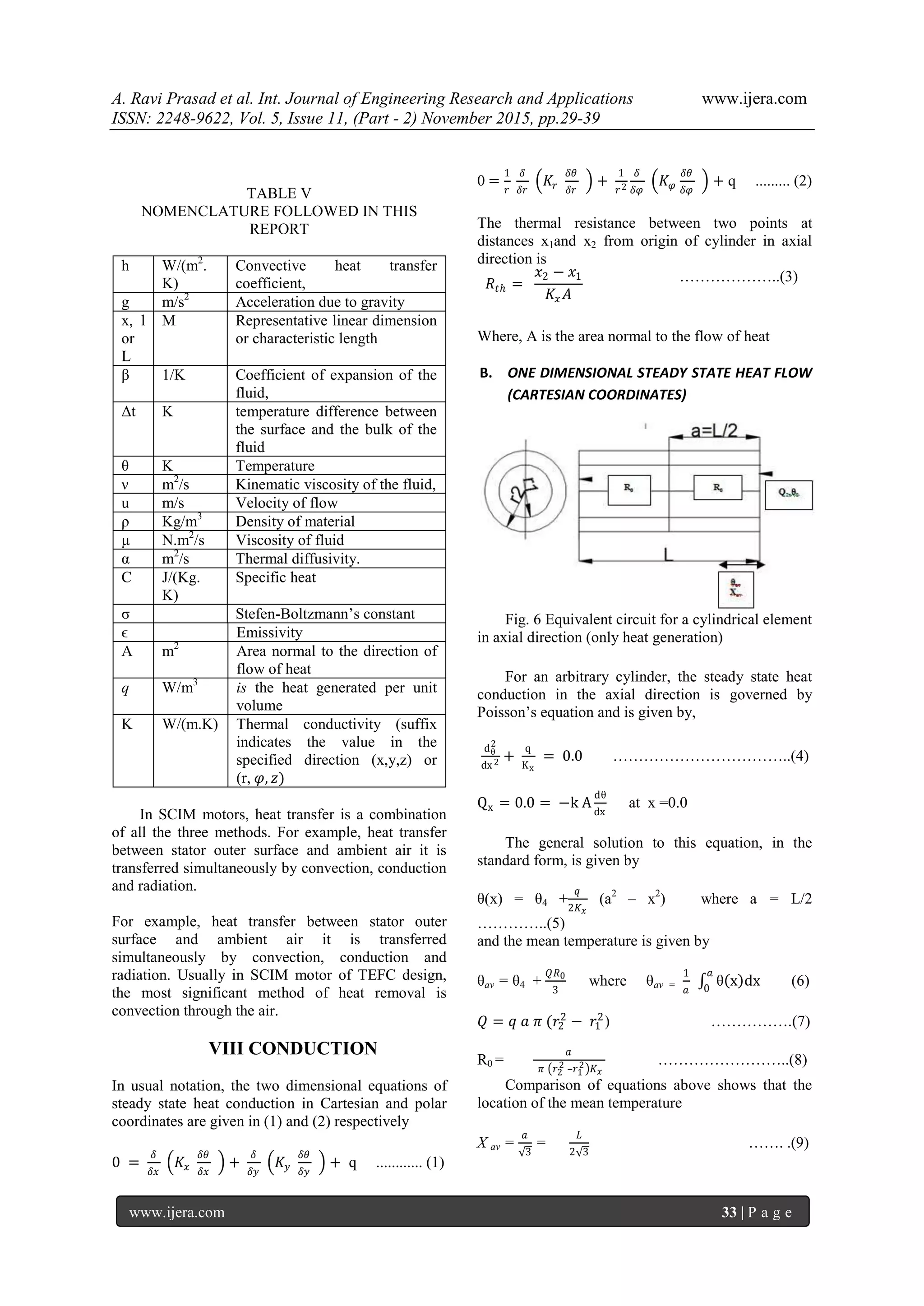
A.GRASHOF NUMBER
For free convection, the GRASHOF number is
used. The significance of the GRASHOF number is
that it represents the ratio of the buoyancy force due
to spatial variation in fluid density (caused by
temperature differences) and the restraining force due
to the viscosity of the fluid.
𝐺𝑟 =
𝑔 𝑙3
𝜈2 βΔθ ………………………………..(23)
B. REYNOLDS NUMBER
Another dimensionless number used is Reynolds
number
𝑅 𝑒 =
𝑢 𝑥
𝜈
……….(24)
Pr =
𝜈
𝛼
=
𝐶 𝑝 𝜇
𝐾
……....(25)
C. PRANDTL NUMBER
PRANDTL number, Pr, is a dimensionless
parameter representing the ratio of diffusion of
momentum to diffusion of heat in a fluid.
D .NUSSELT NUMBER
NUSSELT number, Nu, is the dimensionless
parameter characterizing convective heat transfer. It
is defined as
Nu =
ℎ 𝐿
𝐾
………..(26)
E. TAYLOR NUMBER
Ta = Re
𝑙 𝑔
𝑅 𝑟
…..(27)
Where lg is the air-gap radial thickness, Rr is the rotor
outer radius, and Re the Reynold number
XII. RADIATION
Radiation depends on area, material
characteristics, temperature and surroundings.
Emissivity and absorptivity of a compact body are
assumed to be equal and there is no transmission.
Thus heat exchange depends on radiation angles,
emissivity and temperatures of the interacting
surfaces.
Thermal radiation is not of great significance in
SCIM motor as much as thermal convection and
conduction. Radiation heat transfer is of considerable
significance in the total heat transfer of SCIM motors
if there is only natural convection without any
externally mounted fan on the motor. That is why in
SCIM motor of TEFC design the heat transferred by
radiation is often neglected. Radiation mode of heat
transfer also occurs in inner parts of the SCIM motor,
for instance, between stator end windings or rotor end
rings and the end cap air or from the end cap air to
the frame end caps.
The net amount of heat transferred by radiation
depends on the temperature difference and the
position between heat exchanging surfaces and can
be calculated by
Q = σϵ (𝜃 𝑏
4
− 𝜃𝑠
4
) … . (28)
Where 𝜃 𝑏 == Temperature of body (in K)
𝜃𝑠= Temperature of Surrounding (in K)
Thermal resistance due to radiation is given by
Rth,r =
1
𝜎𝜖𝐴
………………..(29)
XIII. THERMAL NET WORKS
For simplicity, SCIM motor can be considered as
a coaxial system of concentric cylinders representing
the shaft, rotor iron, motor frame, stator iron etc.
based on principles described. Relevant empirical
thermal models found in literature are applied for
calculating thermal resistances. Thermal networks
describe the main paths for heat flow, enabling
temperatures of the main components within the
motor to be predicted for given loss distribution.
Calculation of heat loss values has been done based
on principles quoted in report 3 and 5.
A. UNIFORMITY CONSIDERATIONS FOR
NODES
1. Uniformity of temperatures within the
component and the surfaces
2. Uniformity of the heat generated for the active
component
3. Uniformity of physical properties within each
component
4. Uniformity of exchange conditions by
convection for each of the surfaces
B. FEATURES OF TNM MODELS
1. Nodes are regions (components) of constant
temperature connoting mean temperatures.
2 Heat generations at various positions in motor or
motor losses are Iron losses, Joule losses, stray
load losses and mechanical losses.
3. Thermal resistances are objects of heat
resistances governed by heat conduction and
convection while impact of heat radiation is
given importance at only significant locations.
C. HYPOTHESES FOR SIMPLIFYING TNM
MODELS [4]
1. A motor symmetry is assumed around the shaft
and about the radial plane through the center of
the motor. This leads to the result of using fig.
13 instead of fig.12.
2. The influence of the asymmetrical temperature
distribution that exists in the motor with external
fan mounted at one end is neglected. (Fan end
and no fan end behave thermally in a similar
manner)](https://image.slidesharecdn.com/e511022939-151121061425-lva1-app6892/75/Dimensional-and-Constructional-Details-of-Components-Fundamentals-of-TNM-Method-and-Basics-of-SCIM-Motor-Heat-Transfer-8-2048.jpg)
![A. Ravi Prasad et al. Int. Journal of Engineering Research and Applications www.ijera.com
ISSN: 2248-9622, Vol. 5, Issue 11, (Part - 2) November 2015, pp.29-39
www.ijera.com 39 | P a g e
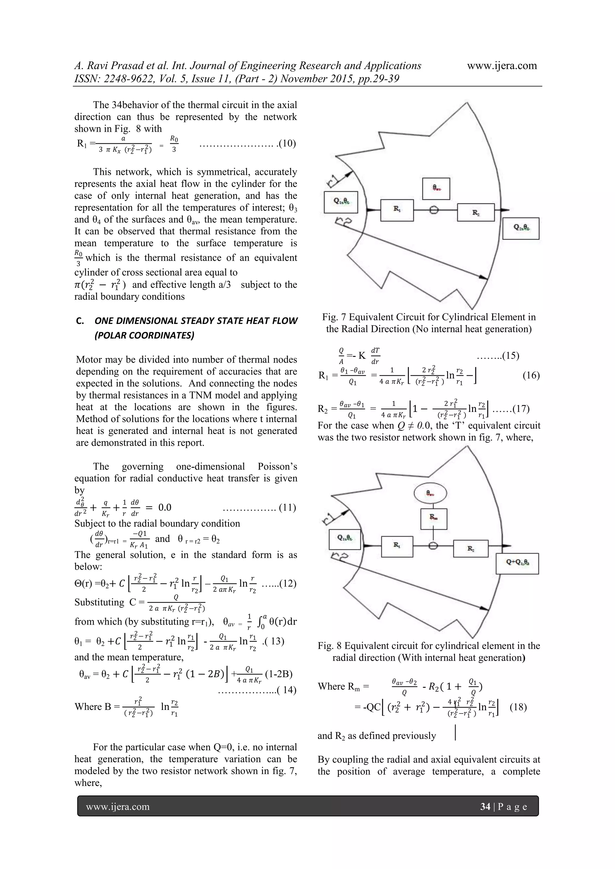
Fig. 13 Combined thermal network for symmetric
component
This combined network allows different thermal
conductivities in the radial and axial directions. Thus,
the thermal effect of the stator and rotor laminations
can be considered.
REFERENCES
[1] PH Mellor, D Roberts, DR Turner, Lumped
parameter thermal model for electrical IEE
PROCEEDINGS-B/ Vol. 138, No. 5, 1/205-
218/machines of TEFC design 1991
SEPTEMBER 1991
[2] Amar BOUSBAINE, An investigation into
the thermal modeling of induction motors‖,
Thesis submitted to Dept., of Electronics
and Electrical Engineering University of
Sheffield for the degree of Doctor of
Philosophy, June 1993.
[3] A. Ravi Prasad, Dr. K Prahlada Rao, ―TNM
Method Results Compared with Finite
Element Analysis for a 30 KW SCIM
Motor‖, Int. Journal of Engineering
Research and Applications, www.ijera.com,
ISSN: 2248-9622, Vol. 5, Issue 10, (Part - 1)
October 2015, pp.22-31
[4] Aldo Boglietti, Andrea Cavagnino, Mario
Lazzari, and Michele Pastorelli, A
Simplified Thermal Model for Variable-
Speed Self-Cooled dustrial Induction Motor
IEEE TRANSACTIONS ON INDUSTRY
APPLICATIONS, VOL. 39, NO. 4,
JULY/AUGUST 2003 945/
θ axial, left = θ
axial, right
Ra
θm, P Rb
θ radial ,outer
Rm
θradial, inner
Rc](https://image.slidesharecdn.com/e511022939-151121061425-lva1-app6892/75/Dimensional-and-Constructional-Details-of-Components-Fundamentals-of-TNM-Method-and-Basics-of-SCIM-Motor-Heat-Transfer-11-2048.jpg)

This document discusses the thermal design improvements for squirrel cage induction motors (SCIM), focusing on the heat transfer methods and component details crucial for optimizing motor efficiency. It explains the design and functions of the motor's key components, such as the stator and rotor, and emphasizes the importance of understanding thermal distribution to enhance motor performance. Additionally, it outlines various methodologies, including the thermal network method, for evaluating and mitigating thermal loads in SCIM motors.


