Training manual boiler general arrangement_mongduong ii
•
4 likes•1,101 views

document about boiler by Hoang Van Duc

Recommended
Recommended
More Related Content
What's hot
What's hot (20)
Similar to Training manual boiler general arrangement_mongduong ii
Similar to Training manual boiler general arrangement_mongduong ii (20)
Recently uploaded
Recently uploaded (20)
Training manual boiler general arrangement_mongduong ii
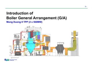
- 1. DOOSAN 1 - Introduction of Boiler General Arrangement (G/A) Mong Duong II TPP (2 x 560MW) 15 3 23 25 9 13 1 22 19 4 20 26 24 5 14 21 16 17 18 2 611 12 87 27 28 29 30 10 31 26A 21A 26B 27A
- 2. DOOSAN Contents 2. Work Boundaries 1. Definition & Mission 2 - 4. Layout Considerations 3. Design Objectives 5. Understanding of G/A Drawing 6. Introduction of G/A for MD II 7. Appendix
- 3. DOOSAN 3 -1. Definition & Mission • The General Arrangement drawing is a basic document which shows the arrangement of the Boiler, Steel Structure, Auxiliary equipments, Air & Gas ducts and Major Piping etc. relative to each other in the Proper area specified by Customer. • The G/A drawing visualizes the actual size of the various equipments and represents them in a scaled down manner in both elevation and plan views. G/A drawing is just for indicating the general information, but all the more information of actual platform area, partial platform elevation and local stair/ladder location etc. refer to the relevant steelwork drawings. • The mission of G/A drawing To ensure optimum arrangement/position of the various equipments within the available space. (Economical efficiency) To ensure easy access and maintenance. To co-ordinate between detailed design and Aux. equipments.
- 4. DOOSAN 4 -2. Work Boundaries TBN/GEN BOPBOP BOILER
- 5. DOOSAN 3. Objectives - Cost estimation - Presentation in the proposal - Guiding contract drafting • For Proposal Stage - Client approval and erection. - Facilitate detailed design engineers on the relative arrangement / location of the various boiler components and guides them during detail engineering. - Provide information for basic design of Steel Structure, Piping & Duct Layout. - Provide knowledge on the location, access, space availability, handling facilities to plan maintenance activities.(To help O&M personnel) - Provide information on interface details with other’s scope of work. (To avoid interference between equipments, steel structure, piping etc.) • For Contract Stage 5 -
- 6. DOOSAN 6 -4. Boiler G/A Considerations (1/3) - Plant Elevation (ex, Mean Sea Level) - Boiler Specification • General Information - Equipment Maintenance Space - Boiler(Furnace) Envelope Dimensions & Instrument Connection Location - Furnace & Back-pass Opening Location (Soot blower, CCTV, Observation Door, Access Door etc.) • Boiler Proper - Buckstay Elevation - Interface & Terminal Point - Thermal Expansion Movement
- 7. DOOSAN 7 - - Fans (F.D Fan, I.D Fan, P.A Fan, Seal Air Fan) • Major Equipments (Location, Dimension & Shape) - GAPH (Gas Air Preheater) - SCAH (Steam Coil Air Heater) - Environmental Equipments (FGD, SCR, ESP) - Equipment Handling Device (Monorail Hoist, Crane, etc) - Elevator (Passenger) 4. Boiler G/A Considerations (2/3)
- 8. DOOSAN 8 - - Duct Configuration Including Size & Shape • Air & Flue Gas System - Column Location and Main Staircase Location • Structural Steel - Maintenance & Access Platform Elevations - Damper, Expansion Joint & Access Door Location - Major Pipe Runs, Pipe Size & Elevations (MS, HR, CR & FW) • Piping - Large Valve Locations (MOV. S/V) - Instrument Connection Location 4. Boiler G/A Considerations (3/3)
- 9. DOOSAN 9 - - Key Plan Drawing • Kind of G/A Drawings 5. Understanding of Boiler G/A Drawing - Plan View Drawing (Floor Plan) - Side & Front/Rear Elevation View Drawing - 3-Dimensional View (by PDS) • Basic Knowledge to Reading the G/A - Unit Quantity (Number) - North Direction & Plant Elevation - Kind of Equipments & Future Facilities - General Notes in Drawing - Legend & Abbreviation etc. in Drawing
- 10. DOOSAN 10 -6. Introduction of G/A for MD II - Key Plan & Each Plan View - Side Elevation View - Front & Rear Elevation View - Reference Picture • Unit Description • General Layout Graphic • Heating Surface & Steam Circuit • Water Circuit (Economizer) • Lifting Device for Equipment Maintenance • Access Door Location in Boiler Pressure Part • G/A Drawings
- 11. DOOSAN 11 - Name of Plant Mong Duong II TPP Generation (MWe) 560MW x 2 units Evaporation 1.912 ton/hr Type of boiler Subcritical, Drum Type and Natural Circulation Balanced Draft, Semi-Outdoor Firing Type Slot Burners (Downshot Firing System) Total 36ea Burners (Slot Burner 24 + Wall Burner 12) Fuel Anthracite Coal Boiler Size (m) Furnace Width : 28.520 Furnace Depth : 22.712 Furnace Height : 55.217 Executing • Design : DOOSAN Babcock & DOOSAN Co-work • Manufacturing : DOOSAN Changwon Factory • Commissioning : DOOSAN Babcock & DOOSAN Co-work Unit Description 15.0° PLATEN SH 600 F W F W ECONOMISER FINAL SH PRI RH 1st BANK PRI RH 3rd BANK PRI RH 2nd BANK PRI SH 1st BANK PRI SH 3rd BANK PRI SH 2nd BANK FINAL RH
- 12. DOOSAN 12-General Layout Graphic 15 3 23 25 9 13 1 22 19 4 20 26 24 5 14 21 16 17 18 2 611 12 87 27 28 29 30 10 31 26A 21A 26B 27A Air Duct System ; Cold air supplied from FD fan is after heated by hot gas in the GAPH. and hot air is transported through wind box into the burner. for combustion. Gas Duct System ; After recovering heat from hot flue gas at the furnace and through to the SCR, GAPH, EP, IDF, FGD(or FGD bypass) and stack and exhausted to atmosphere. Electrostatic Precipitator DESCRIPTION OF COMPONENTS Cold Reheater Pipe Main Steam Pipe Final Superheater Platen Superheater Primary Superheater Downcomers Steam Drum Economizer Feed Water Pipe Furnace Water Wall Silencer Blow Down Tank Hot Reheater Pipe Final Reheater Wall Burner Slot Burner Set Gas Air Preheater Steam Coil Air Heater Forced Draft Fan Seal Air Fan Primary Air Fan Coal Feeder Coal Silo Coal Tripper Tube Mill S.C.R C.I.D Fan Stack Primary Reheater 1 2 3 4 5 6 7 8 9 10 11 12 13 14 15 16 17 18 19 20 21 21A 22 23 Mixed P.A Duct 24 25 26 26A 26B Classifiers Coal Pipes 27 27A Bias Damper 28 29 30 31 SCC Bottom Ash Sys
- 13. DOOSAN 15.0° PLATEN SH 600 F W F W ECONOMISER FINAL SH PRI RH 1st BANK PRI RH 3rd BANK PRI RH 2nd BANK PRI SH 1st BANK PRI SH 3rd BANK PRI SH 2nd BANK FINAL RH 13 -Heating Surface Arrangement & Steam Circuit RH Inlet Header SH Outlet Header High Gas Temperature RH Outlet Header Final Superheater Pass Tertiary Burners Slot Burner Sets Economizer Steam Drum Reheater Pass Superheater Pass Wind box
- 14. DOOSAN 14 -Water Circuit (Economizer) Eco. Inlet Header Steam Drum
- 15. DOOSAN 15 - The boiler pressure parts have been designed / selected to ensure both ready access and long term reliability. : Access Door Access Door Location in Boiler Pressure Part - Size 500 x 500 in Tube walls - Size 500 x 900 in Furnace hopper : Observation Door
- 16. DOOSAN 16 -Equipment Maintenance - Boiler, Equipment Location & Duct Layout Lifting Device Supply List /Per Boiler Equipment Capacity x Q’ty Type Location in G/A Dwg. Remarks 1 F.D Fan (Motor) 20 Ton x 2 Sets Motor Driven, Monorail Hoist -310003/310004 Lifting Height 10m 2 F.D Fan (Rotor) 5 Ton x 2 Sets Motor Driven, Monorail Hoist -310003/310004 Lifting Height 10m 3 P.A Fan (Motor) 16 Ton x 1 Sets Motor Driven, Monorail Hoist -310003/310004 Lifting Height 08m 4 P.A Fan (Rotor) 5 Ton x 1 Sets Motor Driven, Monorail Hoist -310003/310004 Lifting Height 08m 5 I.D Fan (Motor) 29 Ton x 2 Sets Motor Driven, Monorail Hoist -310013/310014 Lifting Height 12m 6 I.D Fan (Rotor) 10 Ton x 1 Sets Motor Driven, Monorail Hoist -310013/310014 Lifting Height 12m 7 Scanner Cooling Air Fan Motor 2 Ton x 1 Set Motor Driven, Monorail Hoist -310005 Lifting Height 08m 8 Gas Air Preheater Basket 2 Ton x 2 Sets Motor Driven, Monorail Hoist -310005 Lifting Height 28m 9 Pulverizer (Motor) 30 Ton x 6 Sets Motor Driven, Monorail Hoist -310004 Lifting Height 14m 10 Pulverizer Ball Charge 2 Ton x 1 Sets Motor Driven, Monorail Hoist -310004 Lifting Height 20m 11 Common Chain Block W/ Geared Trolley 3.5 Ton x 24Sets Manual Not Specified Lifting Height 7m 12 Common Chain Block 2 Ton x 2 Sets Manual Not Specified Lifting Height 5m 13 14 15 16
- 17. DOOSAN 17 -G/A Drawing - (Key plan)
- 18. DOOSAN 18 -G/A Drawing - (Side View)
- 19. DOOSAN 19 -G/A Drawing - (Front View)
- 20. DOOSAN 20 -G/A Drawing - (Rear View)
- 21. DOOSAN 21 -G/A Drawing – (Ground floor Plan View)
- 22. DOOSAN 22 -G/A Drawing - (Plan View “04-04”)
- 23. DOOSAN 23 -G/A Drawing - (Top Plan View)
- 24. DOOSAN Boiler Instrument Insert Location- (Connection Insert list)
- 25. DOOSAN Boiler Instrument Insert Location- (Connection Detail)
- 26. DOOSAN Boiler Instrument Insert Location- (Side Elevation View)
- 27. DOOSAN Boiler Instrument Insert Location- (Plan Section View)
- 28. DOOSAN Support Steel For Ret. Sootblowers (1/2)
- 29. DOOSAN Support Steel For Ret. Sootblowers (2/2)
- 30. DOOSAN 24 -G/A Drawing - (Reference Picture) Furnace Wall Lance Tube Axial Type Fan (F.D fan & I.D fan) Centrifugal Type Fan (G.R fan) Long Retractable Soot Blower
- 31. DOOSAN 26 - 3D Animation 7. Appendix