Download as PDF, PPTX


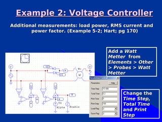
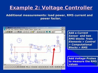
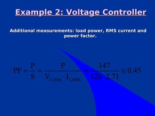
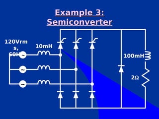
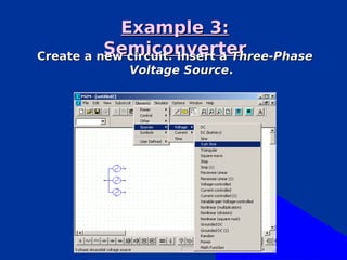

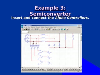

Here are the steps to implement additional measurements for this three-phase semiconverter circuit example: 1. Add current sensors on the load side to measure phase currents 2. Add RMS blocks connected to the current sensors to calculate RMS current values 3. Add a wattmeter to measure load power 4. Calculate power factor using the measured voltage, current RMS values, and load power 5. Add THD blocks connected to the current sensors to calculate the total harmonic distortion of the load currents 6. Simulate the circuit for different alpha angles and record the additional measurement results This allows a more complete analysis of the circuit performance including harmonic distortion, power quality, and efficiency. Let me know if


![Fundamentals of power electronics [presentation slides] 2nd ed r. erickson ww](https://cdn.slidesharecdn.com/ss_thumbnails/fundamentalsofpowerelectronicspresentationslides2nded-r-ericksonww-100522135011-phpapp02-thumbnail.jpg?width=640&height=640&fit=bounds)


![Getting Started with Apache Spark: Big Data Made Simple [Free Meetup]](https://cdn.slidesharecdn.com/ss_thumbnails/apachesparkgettingstarted-260203175547-8361bcc3-thumbnail.jpg?width=640&height=640&fit=bounds)


