Downloaded 11 times
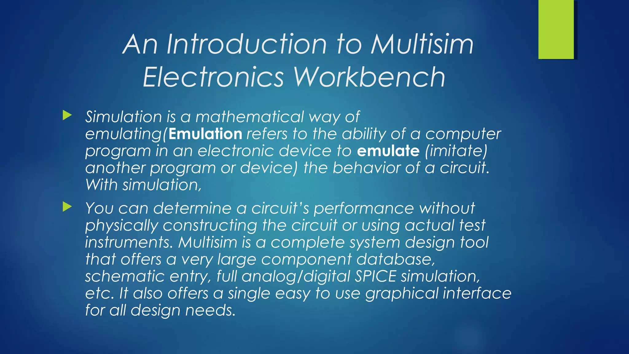
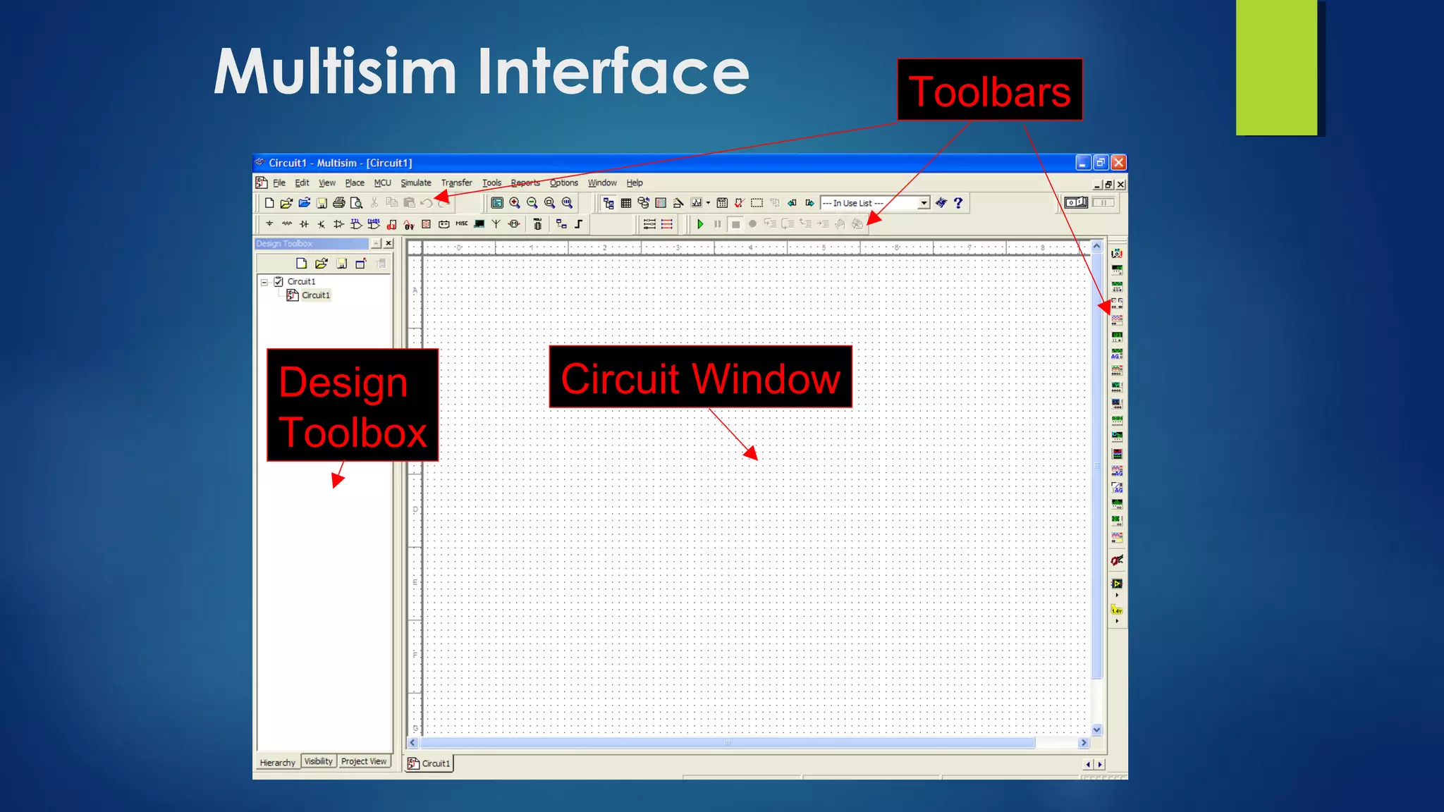
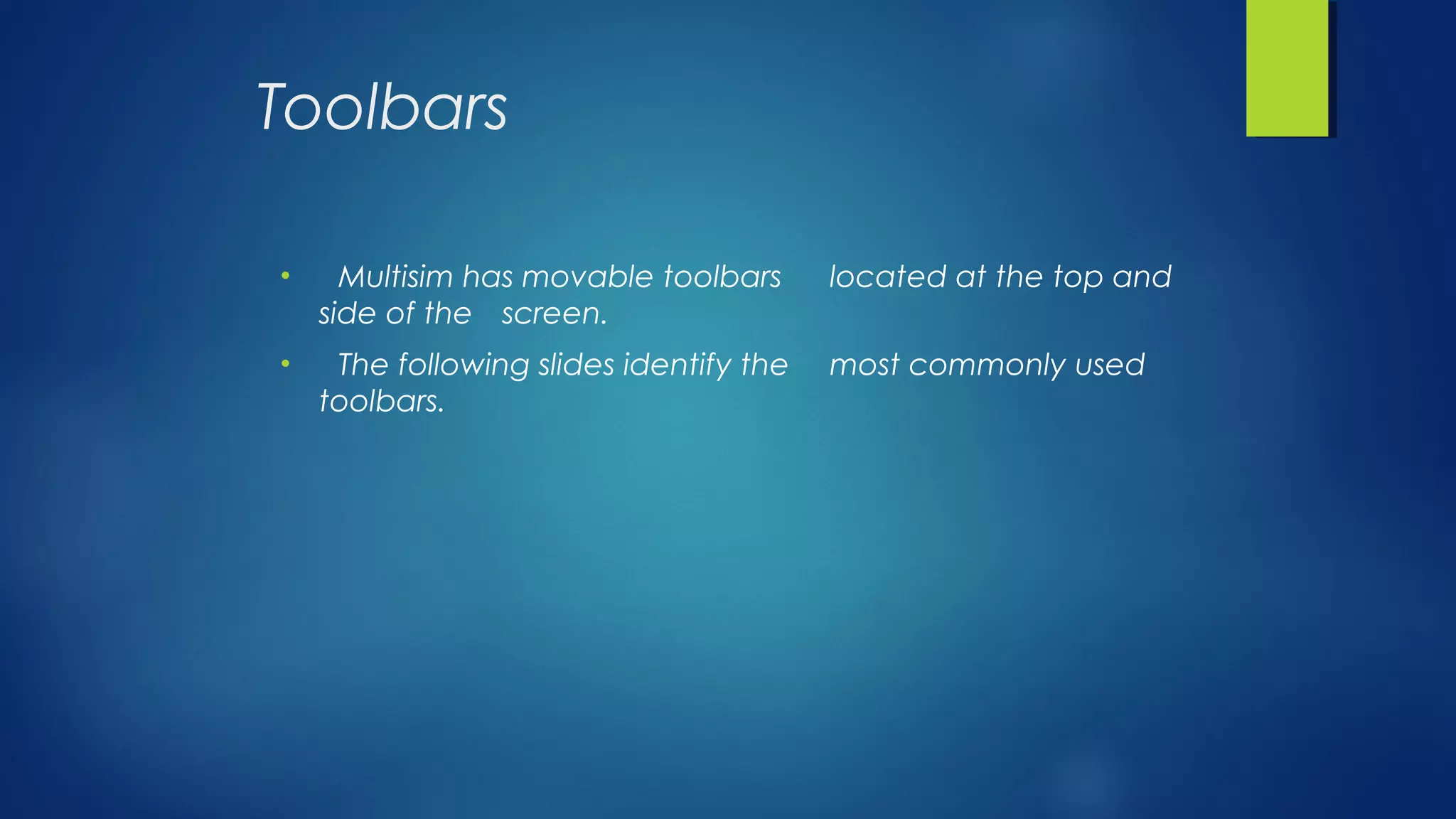
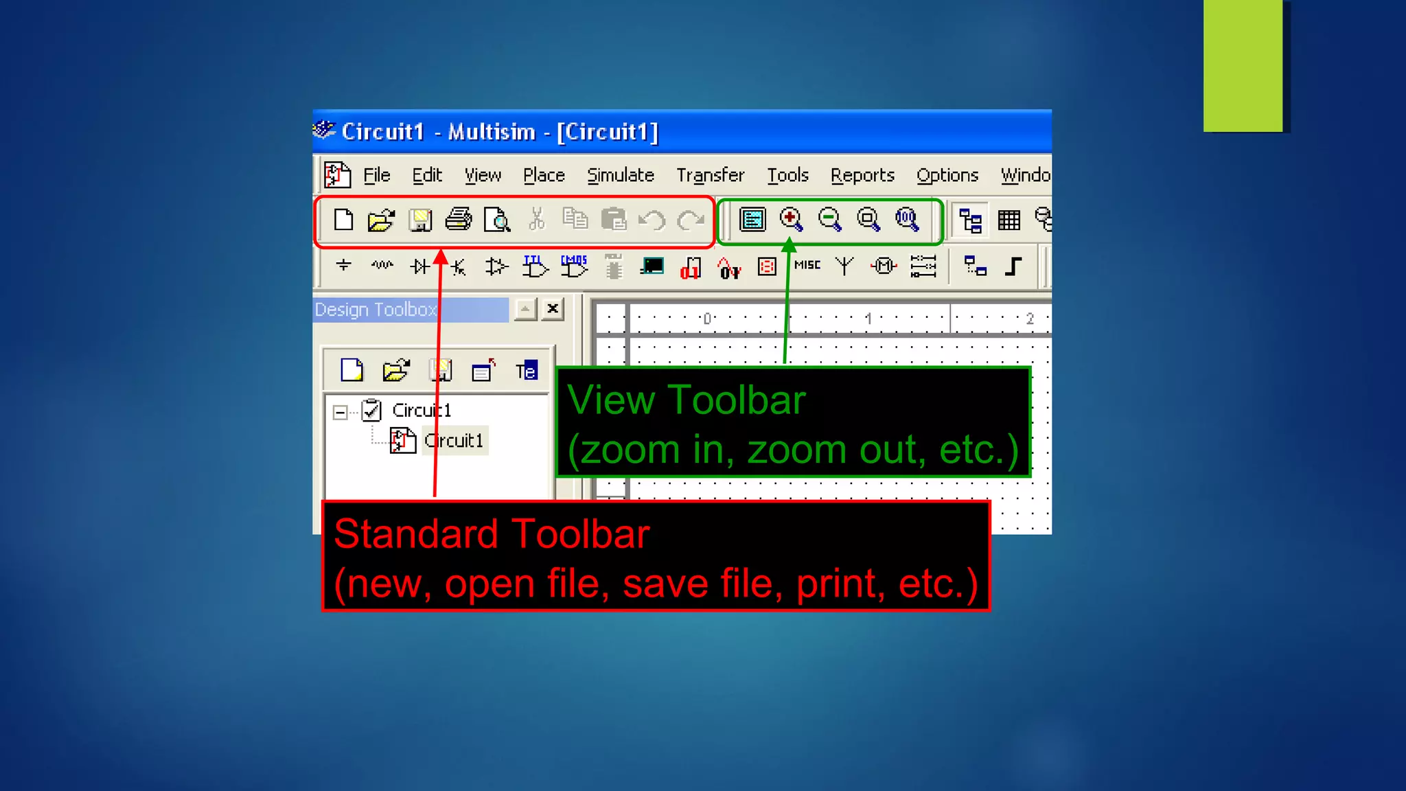
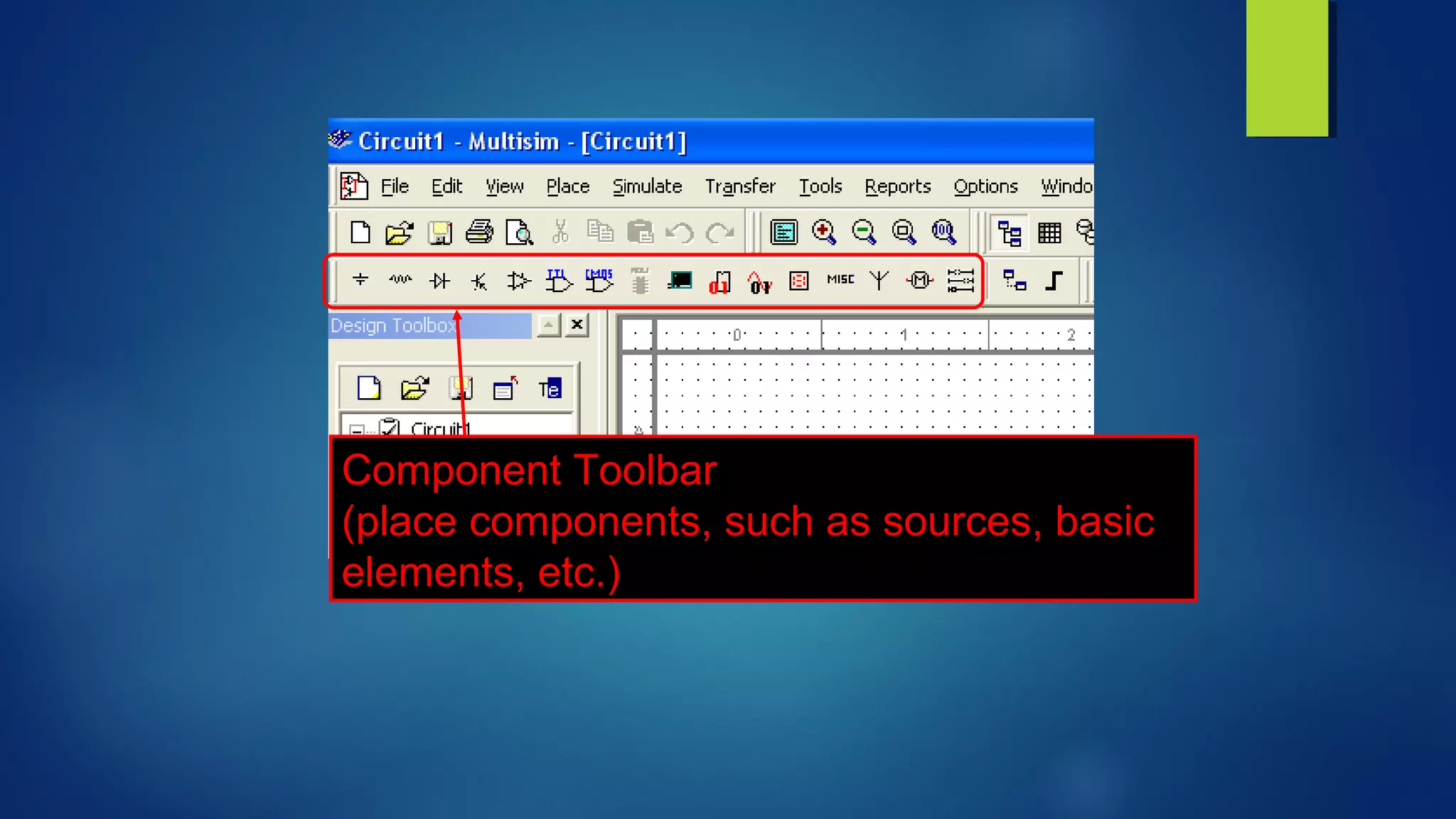
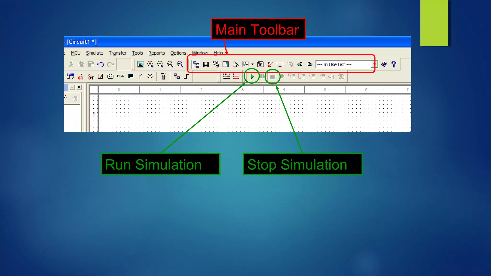
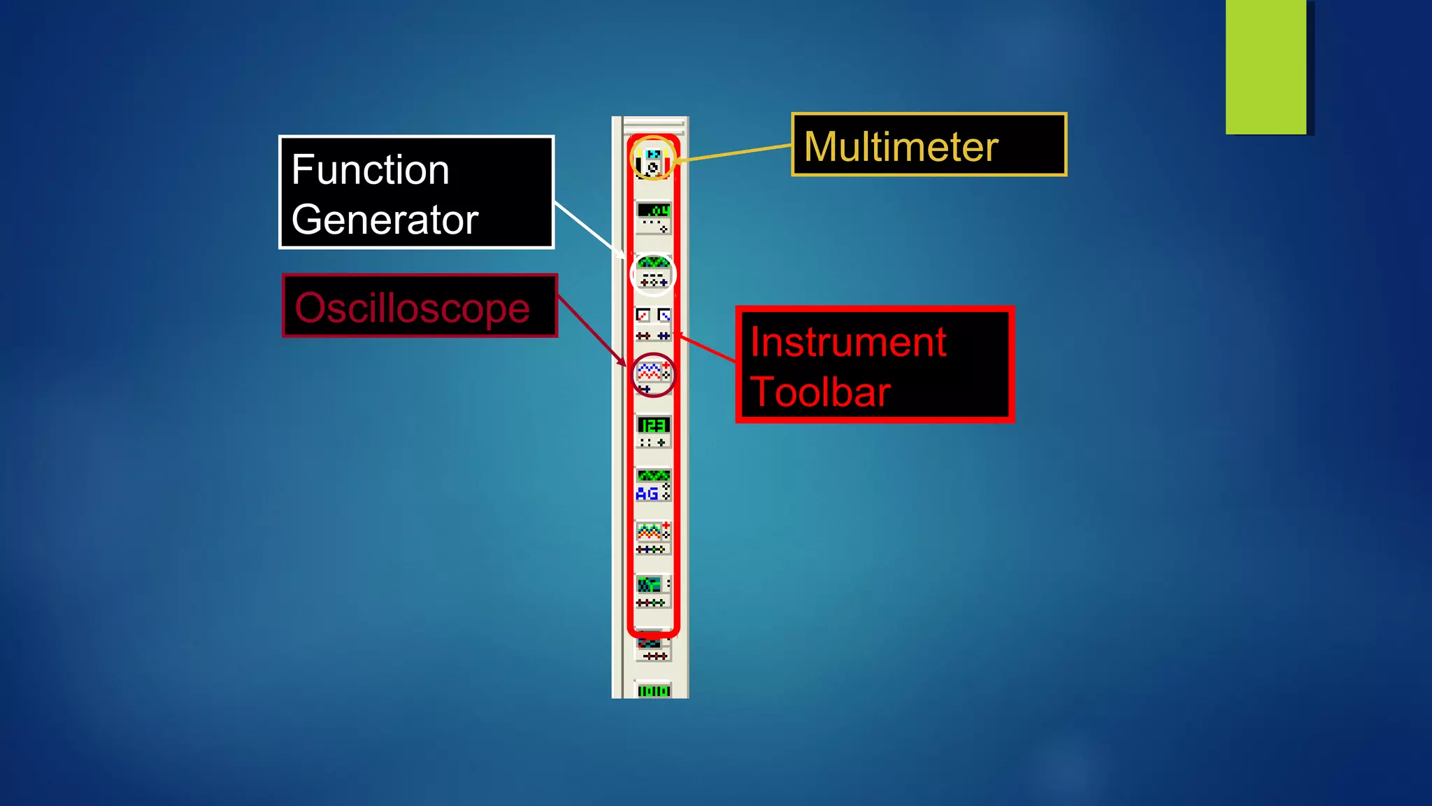
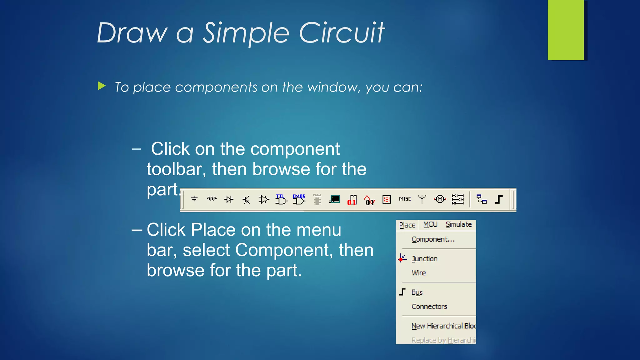
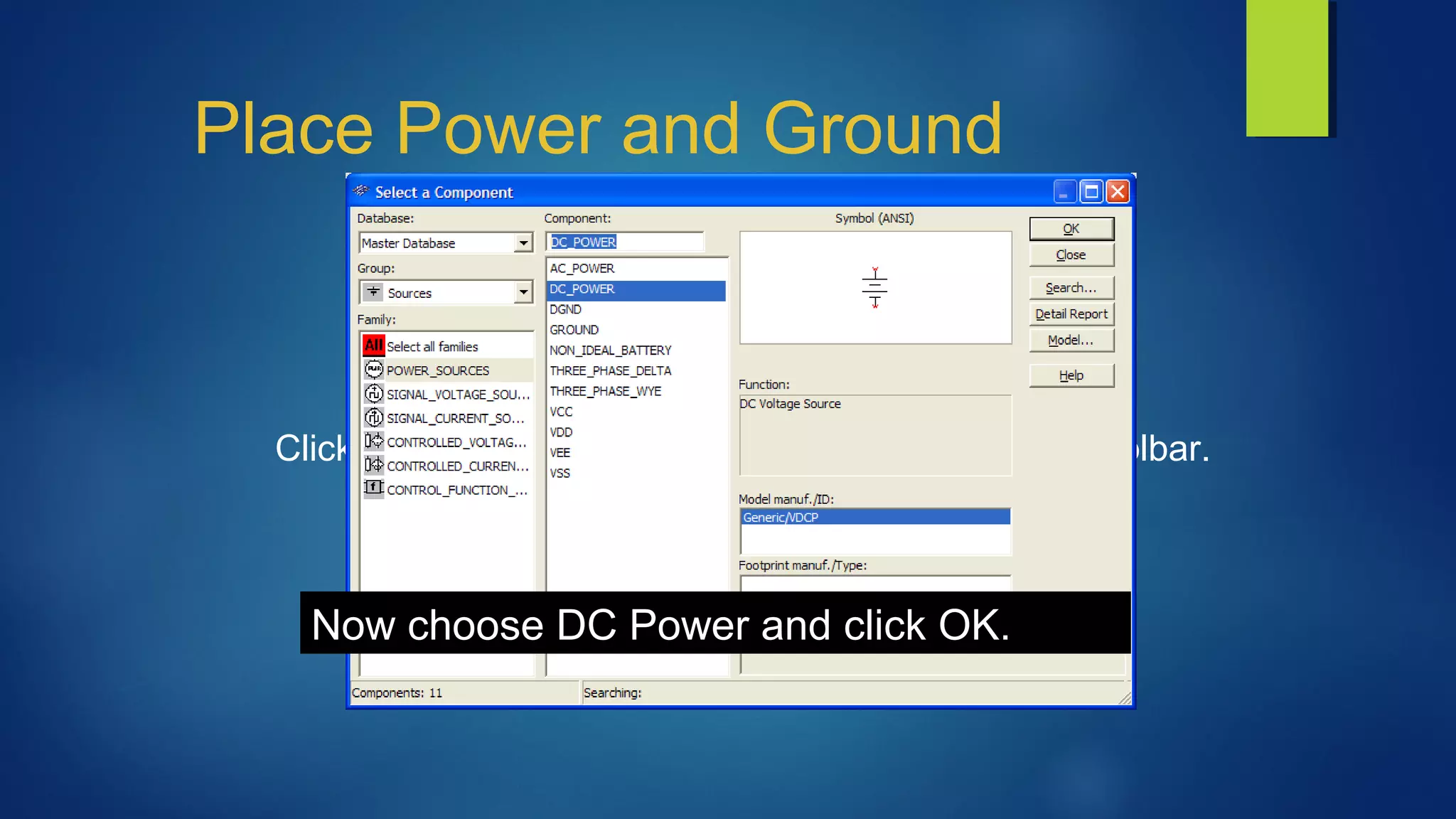
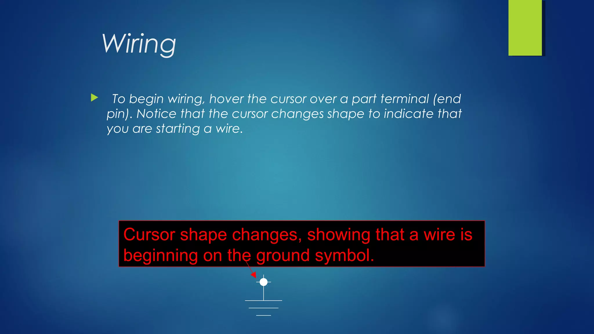

The document provides an introduction to Multisim, an electronic simulation software, detailing its features such as a large component database, schematic entry, and SPICE simulation. It includes a tutorial on using the Multisim interface, covering component placement, wiring, and simulation running. Various toolbars, including standard, view, and instrument toolbars, are addressed, along with wiring hints and the differences between virtual and real components.


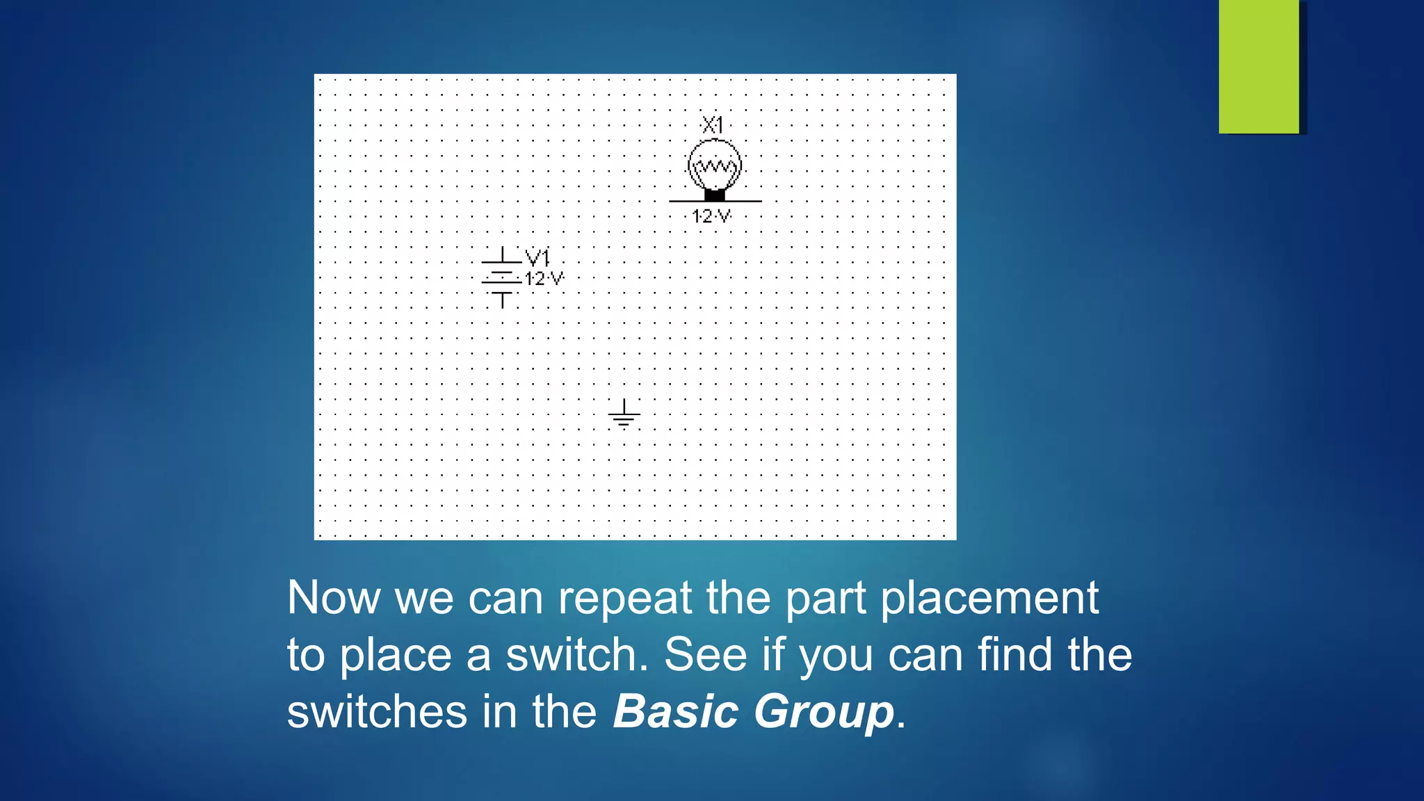
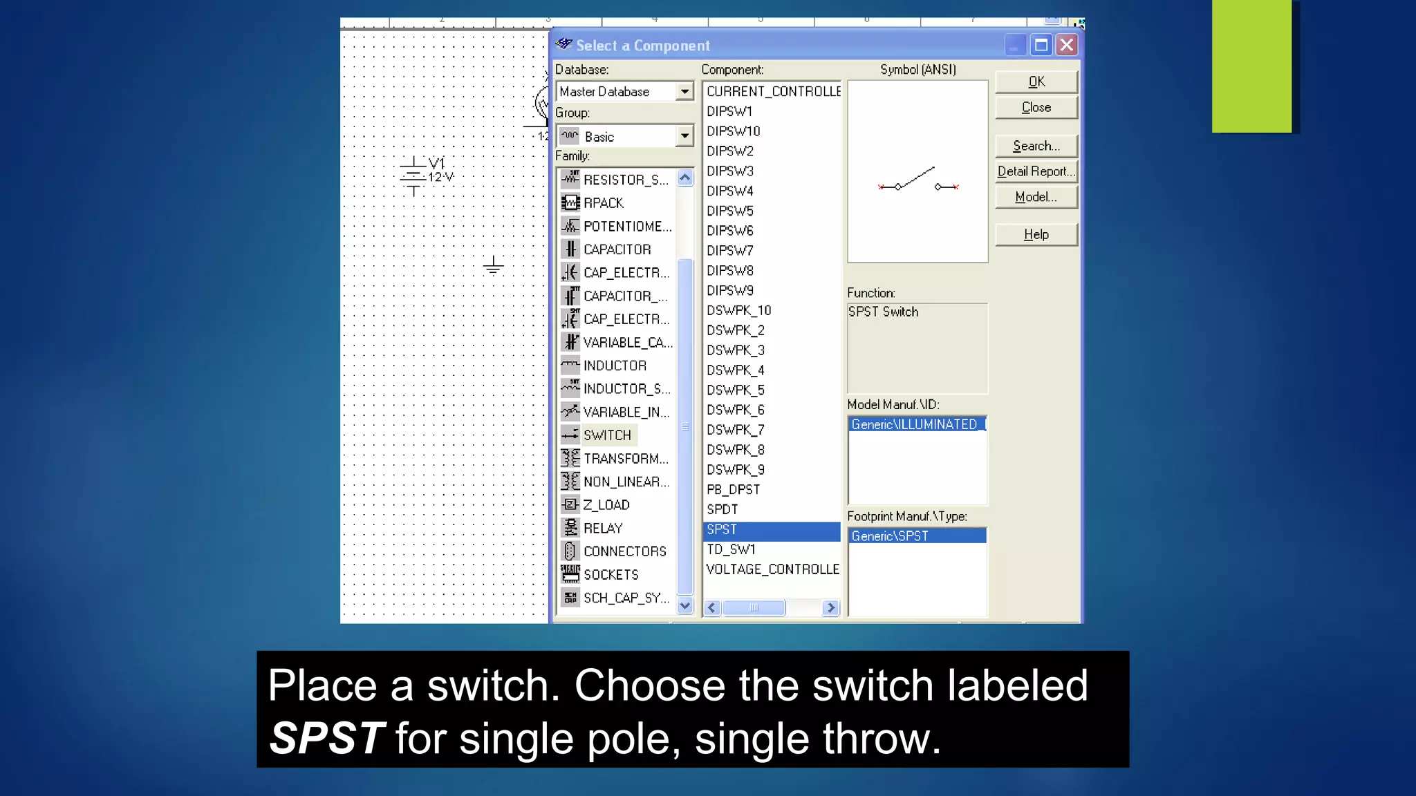
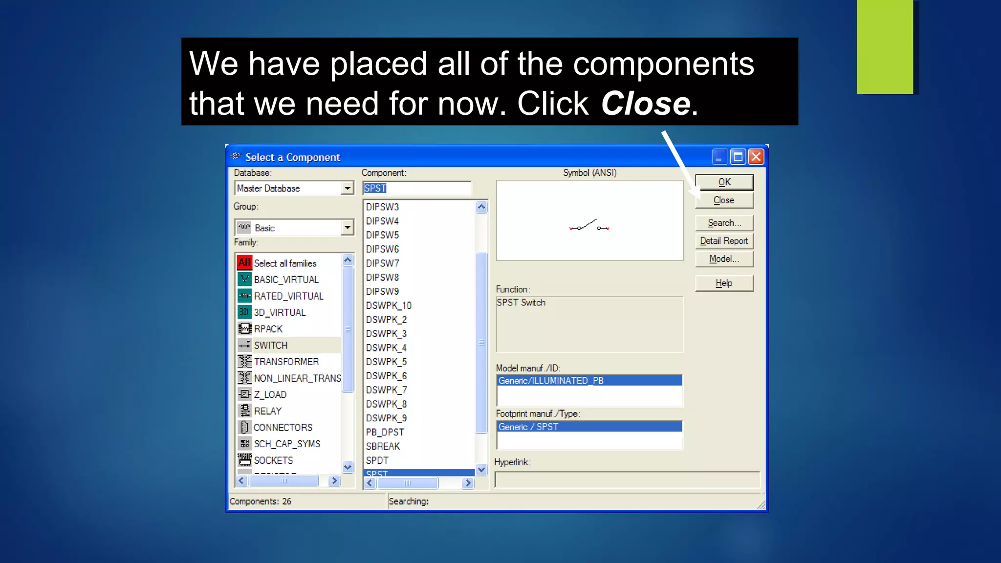
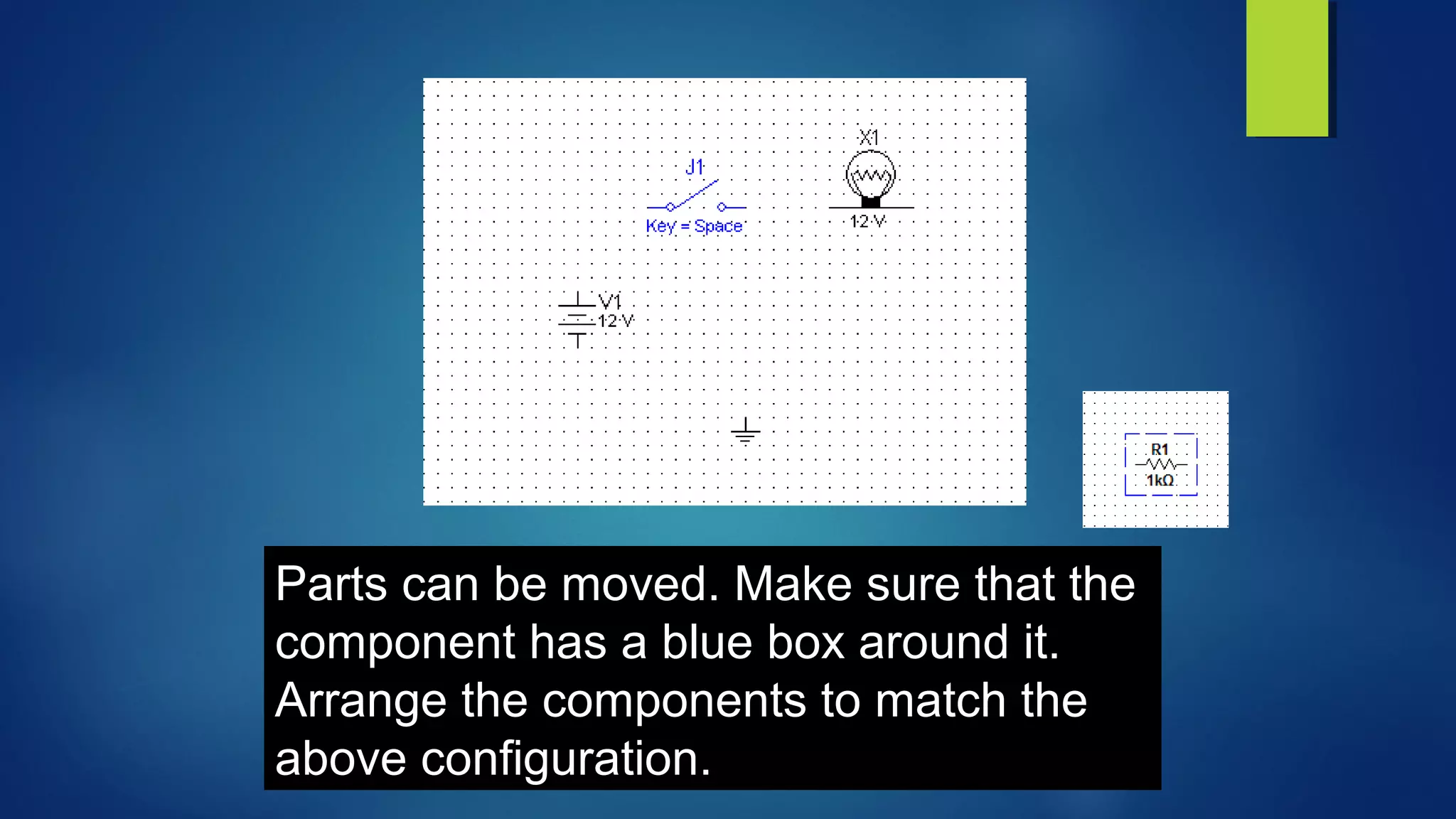
![[Advantech] WebOP designer Tutorial step by step](https://cdn.slidesharecdn.com/ss_thumbnails/1-161115131640-thumbnail.jpg?width=640&height=640&fit=bounds)


