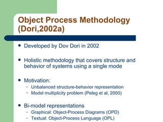
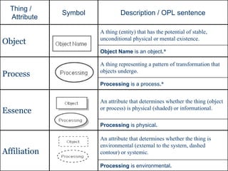
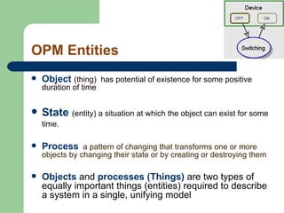
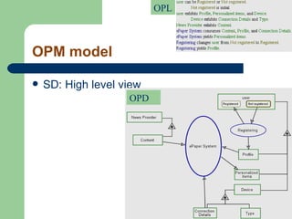
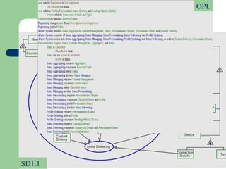
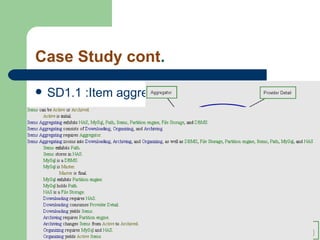
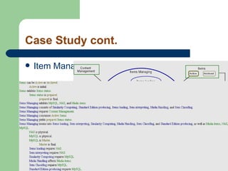
Object Process Methodology (OPM) By: Ibrahim Sana
Agenda Definitions OPM-Introduction Notations Complexity management Case Study: Epaper Project OPM Evaluation  Case tool OPCAT OPCATeam
Definitions for system “ A group of interdependent  items  that  interact  regularly to perform a task”(webopedia.com)  “ A collection of  components  organized to  accomplish  a specific function or set of functions” (IEEE Std. 610.12-1990 ) System has two aspects: Structure (Static) Behavior (Dynamic)
Methodologies types Methodologies can be classified into three categories Structure (OO) Example: Class Diagram,ERD Behavior (PO) Example: DFD, statechart Hybrids(OO and PO) Example:UML, OPM
Object Process Methodology (Dori,2002a) Developed by Dov Dori in 2002 Holistic methodology that c overs structure and behavior of systems  using a single mode Motivation: Unbalanced structure-behavior representation Model multiplicity problem (Peleg et al, 2000) Bi-model representations Graphical: Object-Process Diagrams (OPD) Textual: Object-Process Language (OPL)
Processing  is environmental . An attribute that determines whether the thing is environmental (external to the system, dashed contour) or systemic. Affiliation Processing  is physical . An attribute that determines whether the thing (object or process) is physical (shaded) or informational. Essence Processing  is a process . * A thing representing a pattern of transformation that objects undergo. Process Object Name  is an object . * A thing (entity) that has the potential of stable, unconditional physical or mental existence. Object Description / OPL sentence Symbol Thing /  Attribute
OPM   Entities Object   (thing)  has potential of existence for some positive duration of time State  (entity) a situation at which the object can exist for some time.   Process   a pattern of changing that transforms one or more objects by changing their state or by creating or destroying them Objects  and  processes (Things)  are two types of equally important things (entities) required to describe a system in a single, unifying model
The System structure   Structure: the stable aspect of the system Object/Process associated with structural relations Structural relations General relation Tagged structural links  Fundamental relations Aggregation-Particulation  Featuring-Characterization Generalization-Specialization
General relation Tagged structural links Unidirectional Bidirectional
Fundamental relations Aggregation-Particulation  Featuring-Characterization Generalization-Specialization
The System Behavior Behavior: the dynamic aspect of the system Objects and Process associated with procedural links Procedural Links Enabling link Transformation link
Enablers and Enabling link Enabler: is an object that must be present in order for that process to occur but is not transformed by the process Enabling link: Agent Instrument
Transformation links Effect Link :connects a process with its affected object or with the affected object states. Consumption Link: connects a process with a consumed object of that process Result Link: connects a process with a resulting object of that process
Complexity management Completeness vs. Clarity OPM scaling mechanism Unfolding/Folding for structural relations Zooming-in/Zooming out for procedural relations State expressing/suppressing
Case Study :  Epaper Project  Aggregating news content from several providers Content management Building subscribers profiles Initial profile (content-based) Collaborative filtering Sending news items that matching the user’s profile
OPM model   SD: High level view OPD OPL
OPM Model cont. SD1.1 (Zooming-In) SD1.1 OPL
Case Study cont . SD1.1 :Item aggregating
Case Study cont. Item Managing (SD1.1)
Case Study cont. Item Delivering (SD1.1)
OPM map SD SD1 SD1.1 SD1.2 SD1.3
OPM   vs. UML UML has multiple-views Each view specifies a different aspect  The diagram types are divided into: Structural diagrams Procedural diagrams
UML   views Use Case Diagrams Use Case Diagrams Use Case Diagrams Scenario Diagrams Scenario Diagrams Collaboration Diagrams State Diagrams State Diagrams Component Diagrams Component Diagrams Component Diagrams Deployment Diagrams State Diagrams State Diagrams Object Diagrams Scenario Diagrams Scenario Diagrams Statechart Diagrams Use Case Diagrams Use Case Diagrams Sequence Diagrams State Diagrams State Diagrams Class Diagrams Activity Diagrams Models
OPM   vs.  UML OPM : Process is an entity that uniformly represents patterns of behavior UML : Behavior of the system can be spread across five diagram types OPM : System’s structure and behavior are specified side-by-side, enabling one to see the whole picture in a single view UML : System’s structure and  behavior are specified  at different and separate  views
OPM vs.  UML OPM : No need for mental transformations and integration across different views UML : Need to validate consistency among the various views OPM :25 symbols  UML : 150 symbols (Dori,2002)
UML vs. OPM experiment (Iris,2002) The subjects: 3rd year students at the Technion The experiment took place during the final examination of the course “Specification and Analysis of IS” (spring, 2002)  Tasks
Experiment Design Task2 OPM Model UML Model Task1 OPM Model UML Model Task1 Task2 UML OPM Group1: Group2: Task1 Task2 OPM UML
Experiment Design They learned OPM for two weeks and UML for five weeks Neutral course stuff Five diagrams followed by 8 comprehension questions and one modeling problem Identical questions per task Questions related to the system structure, dynamic, and distribution Fair grading policy
Hypothesis UML class diagram would better serve subjects who are looking for answers to questions related to the structural parts of a given system OPM will be more adequate than UML for understanding the dynamic aspect of the system and the complex relations among various system modules OPM expected to e more correctly and more easily applied than UML for modeling complex, dynamic applications
Results
OPCAT (www.opcat.com) OPCAT (Object-Process CAse Tool) has been developed as a CASE tool to support the Object-Process Methodology. Graphic and textual representation, jointly express the same OPM model OPL serves human as well as machine OPCAT provide an advanced simulation tool OPCAT enable code generation (using OPL) OPCAT enable UML diagrams generation
OPCAT overview Entities Structural links Procedural links
Simulation by animation
OPCATeam Project (Beimel,2004) OPM-based Collaborative Systems Modeling  Create collaborative environment, where teams of modelers collaborate in analysis, design, and implementation of systems using OPM.  Multi users, Client-Server architecture. Users can simultaneously update the models, through the clients according to their access permissions. Includes a version control function that logs updates and enables revision control.
References Peleg, M. and Dori, D. The Model Multiplicity Problem: Experimenting with Real-Time Specification Methods. IEEE Transaction on Software Engineering, 26 (8), pp. 742–759,2000. Dori, D. Object-Process Methodology – A Holistic Systems Paradigm, Springer Verlag,Berlin, Heidelberg, New York, 2002. Dori, D. Reinhartz-Berger, I. and Sturm A. OPCAT – A Bimodal Case Tool for Object-Process Based System Development. 5th International Conference on EnterpriseInformation Systems (ICEIS 2003), pp. 286–291, 2003. Software download site:http://www.objectprocess.org Iris Reinhartz-Berger and Dov Dori, OPM vs. UML - Experimenting with Comprehension and Construction of Web Application Models.Empirical Software Engineering 10, 1, pp. 57-80, 2005.


Object Process Methodology

  • 1.
    Object Process Methodology(OPM) By: Ibrahim Sana
  • 2.
    Agenda Definitions OPM-IntroductionNotations Complexity management Case Study: Epaper Project OPM Evaluation Case tool OPCAT OPCATeam
  • 3.
    Definitions for system“ A group of interdependent items that interact regularly to perform a task”(webopedia.com) “ A collection of components organized to accomplish a specific function or set of functions” (IEEE Std. 610.12-1990 ) System has two aspects: Structure (Static) Behavior (Dynamic)
  • 4.
    Methodologies types Methodologiescan be classified into three categories Structure (OO) Example: Class Diagram,ERD Behavior (PO) Example: DFD, statechart Hybrids(OO and PO) Example:UML, OPM
  • 5.
    Object Process Methodology(Dori,2002a) Developed by Dov Dori in 2002 Holistic methodology that c overs structure and behavior of systems using a single mode Motivation: Unbalanced structure-behavior representation Model multiplicity problem (Peleg et al, 2000) Bi-model representations Graphical: Object-Process Diagrams (OPD) Textual: Object-Process Language (OPL)
  • 6.
    Processing isenvironmental . An attribute that determines whether the thing is environmental (external to the system, dashed contour) or systemic. Affiliation Processing is physical . An attribute that determines whether the thing (object or process) is physical (shaded) or informational. Essence Processing is a process . * A thing representing a pattern of transformation that objects undergo. Process Object Name is an object . * A thing (entity) that has the potential of stable, unconditional physical or mental existence. Object Description / OPL sentence Symbol Thing / Attribute
  • 7.
    OPM Entities Object (thing) has potential of existence for some positive duration of time State (entity) a situation at which the object can exist for some time. Process a pattern of changing that transforms one or more objects by changing their state or by creating or destroying them Objects and processes (Things) are two types of equally important things (entities) required to describe a system in a single, unifying model
  • 8.
    The System structure Structure: the stable aspect of the system Object/Process associated with structural relations Structural relations General relation Tagged structural links Fundamental relations Aggregation-Particulation Featuring-Characterization Generalization-Specialization
  • 9.
    General relation Taggedstructural links Unidirectional Bidirectional
  • 10.
    Fundamental relations Aggregation-Particulation Featuring-Characterization Generalization-Specialization
  • 11.
    The System BehaviorBehavior: the dynamic aspect of the system Objects and Process associated with procedural links Procedural Links Enabling link Transformation link
  • 12.
    Enablers and Enablinglink Enabler: is an object that must be present in order for that process to occur but is not transformed by the process Enabling link: Agent Instrument
  • 13.
    Transformation links EffectLink :connects a process with its affected object or with the affected object states. Consumption Link: connects a process with a consumed object of that process Result Link: connects a process with a resulting object of that process
  • 14.
    Complexity management Completenessvs. Clarity OPM scaling mechanism Unfolding/Folding for structural relations Zooming-in/Zooming out for procedural relations State expressing/suppressing
  • 15.
    Case Study : Epaper Project Aggregating news content from several providers Content management Building subscribers profiles Initial profile (content-based) Collaborative filtering Sending news items that matching the user’s profile
  • 16.
    OPM model SD: High level view OPD OPL
  • 17.
    OPM Model cont.SD1.1 (Zooming-In) SD1.1 OPL
  • 18.
    Case Study cont. SD1.1 :Item aggregating
  • 19.
    Case Study cont.Item Managing (SD1.1)
  • 20.
    Case Study cont.Item Delivering (SD1.1)
  • 21.
    OPM map SDSD1 SD1.1 SD1.2 SD1.3
  • 22.
    OPM vs. UML UML has multiple-views Each view specifies a different aspect The diagram types are divided into: Structural diagrams Procedural diagrams
  • 23.
    UML views Use Case Diagrams Use Case Diagrams Use Case Diagrams Scenario Diagrams Scenario Diagrams Collaboration Diagrams State Diagrams State Diagrams Component Diagrams Component Diagrams Component Diagrams Deployment Diagrams State Diagrams State Diagrams Object Diagrams Scenario Diagrams Scenario Diagrams Statechart Diagrams Use Case Diagrams Use Case Diagrams Sequence Diagrams State Diagrams State Diagrams Class Diagrams Activity Diagrams Models
  • 24.
    OPM vs. UML OPM : Process is an entity that uniformly represents patterns of behavior UML : Behavior of the system can be spread across five diagram types OPM : System’s structure and behavior are specified side-by-side, enabling one to see the whole picture in a single view UML : System’s structure and behavior are specified at different and separate views
  • 25.
    OPM vs. UML OPM : No need for mental transformations and integration across different views UML : Need to validate consistency among the various views OPM :25 symbols UML : 150 symbols (Dori,2002)
  • 26.
    UML vs. OPMexperiment (Iris,2002) The subjects: 3rd year students at the Technion The experiment took place during the final examination of the course “Specification and Analysis of IS” (spring, 2002) Tasks
  • 27.
    Experiment Design Task2OPM Model UML Model Task1 OPM Model UML Model Task1 Task2 UML OPM Group1: Group2: Task1 Task2 OPM UML
  • 28.
    Experiment Design Theylearned OPM for two weeks and UML for five weeks Neutral course stuff Five diagrams followed by 8 comprehension questions and one modeling problem Identical questions per task Questions related to the system structure, dynamic, and distribution Fair grading policy
  • 29.
    Hypothesis UML classdiagram would better serve subjects who are looking for answers to questions related to the structural parts of a given system OPM will be more adequate than UML for understanding the dynamic aspect of the system and the complex relations among various system modules OPM expected to e more correctly and more easily applied than UML for modeling complex, dynamic applications
  • 30.
  • 31.
    OPCAT (www.opcat.com) OPCAT(Object-Process CAse Tool) has been developed as a CASE tool to support the Object-Process Methodology. Graphic and textual representation, jointly express the same OPM model OPL serves human as well as machine OPCAT provide an advanced simulation tool OPCAT enable code generation (using OPL) OPCAT enable UML diagrams generation
  • 32.
    OPCAT overview EntitiesStructural links Procedural links
  • 33.
  • 34.
    OPCATeam Project (Beimel,2004)OPM-based Collaborative Systems Modeling Create collaborative environment, where teams of modelers collaborate in analysis, design, and implementation of systems using OPM. Multi users, Client-Server architecture. Users can simultaneously update the models, through the clients according to their access permissions. Includes a version control function that logs updates and enables revision control.
  • 35.
    References Peleg, M.and Dori, D. The Model Multiplicity Problem: Experimenting with Real-Time Specification Methods. IEEE Transaction on Software Engineering, 26 (8), pp. 742–759,2000. Dori, D. Object-Process Methodology – A Holistic Systems Paradigm, Springer Verlag,Berlin, Heidelberg, New York, 2002. Dori, D. Reinhartz-Berger, I. and Sturm A. OPCAT – A Bimodal Case Tool for Object-Process Based System Development. 5th International Conference on EnterpriseInformation Systems (ICEIS 2003), pp. 286–291, 2003. Software download site:http://www.objectprocess.org Iris Reinhartz-Berger and Dov Dori, OPM vs. UML - Experimenting with Comprehension and Construction of Web Application Models.Empirical Software Engineering 10, 1, pp. 57-80, 2005.
  • 36.
  • 37.
  • 38.