Downloaded 1,084 times


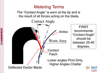


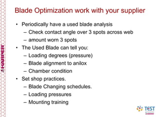


The document discusses the function and mechanics of doctor blades in anilox ink metering, emphasizing their role in controlling ink transfer to printing plates. It explains the differences between forward and reverse doctoring, detailing the impact of blade properties such as stiffness, thickness, and angles on ink metering efficiency. Additionally, it covers best practices for selecting and maintaining doctor blades to optimize print quality and minimize wear on anilox rollers.


