1. 7
High Voltage Generators
for Testing
7.0 Generation of High Voltages
The power systems engineers is interested in high voltages primarily for power transmission, and secondly for
testing of his equipment used in power transmission. In this chapter we are interested in generating high
voltages for testing of insulation. Thus generation has to be carried out in the testing laboratory. In many testing
laboratories, the primary source of power is at low voltage (400 V three phase or 230 V single phase, at 50 Hz).
Thus we need to be able to obtain the high voltage from this. Since insulation is usually being tested, the
impedances involved are extremely high (order of M DQGWKHFXUrents small (less than an ampere). Therefore
high voltage testing does not usually require high power. Thus special methods may be used which are not
applicable when generating high voltage in high power applications.
7.1 Generation of High Alternating Voltages
Single transformer test units are made for high alternating voltages up to about 200 kV.
However, for high voltages to reduce the cost (insulation cost increases rapidly with voltage) and make
transportation easier, a cascade arrangement of several transformers is used.
7.1.1 Cascade arrangement of transformers
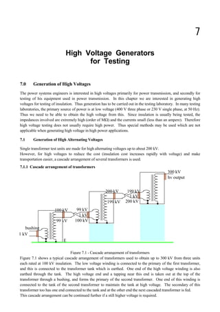
Figure 7.1 shows a typical cascade arrangement of transformers used to obtain up to 300 kV from three units
each rated at 100 kV insulation. The low voltage winding is connected to the primary of the first transformer,
and this is connected to the transformer tank which is earthed. One end of the high voltage winding is also
earthed through the tank. The high voltage end and a tapping near this end is taken out at the top of the
transformer through a bushing, and forms the primary of the second transformer. One end of this winding is
connected to the tank of the second transformer to maintain the tank at high voltage. The secondary of this
transformer too has one end connected to the tank and at the other end the next cascaded transformer is fed.
This cascade arrangement can be continued further if a still higher voltage is required.
Figure 7.1 - Cascade arrangement of transformers
Insulating
Pedestal
Insulating
Pedestal
1 kV
99 kV
100 kV
1 kV
199 kV
200 kV
1 kV
200 kV
100 kV
hv output
300 kV
bushing
E
99 kV
100 kV
199 kV
200 kV
2. High Voltage Engineering - J R Lucas 2001
124
In the cascade arrangement shown, each transformer needs only to be insulated for 100 kV, and hence the
transformer can be relatively small. If a 300 kV transformer had to be used instead, the size would be
massive. High voltage transformers for testing purposes are designed purposely to have a poor regulation.
This is to ensure that when the secondary of the transformer is short circuited (as will commonly happen in
flash-over tests of insulation), the current would not increase to too high a value and to reduce the cost. In
practice, an additional series resistance (commonly a water resistance) is also used in such cases to limit the
current and prevent possible damage to the transformer.
What is shown in the cascade transformer arrangement is the basic principle involved. The actual arrangement
could be different for practical reasons.
7.1.2 Resonant Transformers
The resonance principle of a series tuned L-C circuit can be made use of to obtain a higher voltage with a given
transformer.
Let R represent the equivalent parallel resistance across the coil and the
device under test. The current i would be given by
Since R is usually very large, the Q factor of the circuit (Q = R/L would be very large, and the output voltage
would be given by
It can thus be seen that a much larger value that the input can be obtained across the device under test in the
resonant principle.
Figure 7.3 shows the application of the resonance principle at power frequency.
{FFFFFFFFFFFI
G
G
G
E ∧ G
GFFOFF
GFFNFF
GG
GG
GLFFFFFFNFFFFFF{
GGG
GHOIY∧
GGGG
GGGG
G/GG5G
GGG
JNK
GG
{FFFFFFFFFFFOFFFFFFOFFFFFF{
Figure 7.2 - Resonance circuit
resonance
at
L
j
R
.
E
-
=
R
C
L
-
L
j
+
R
E
.
R
C
L
-
=
v
.
e
.
i
L
j
+
R
R
L
j
.
i
=
v
that
so
2
2
ω
ω
ω
ω
ω
ω
ω
ω
ω L
j
+
R
R
L
j
+
C
j
1
E
=
i
Q
.
E
=
L
R
.
E
=
|
v
|
ω
C
L
1
=
f
2
=
resonance
at π
ω
FFFFFFFFFFFFFFFFFFIFFFFFFFFFFFFFFFFFFFFFFFI
G
G G
FFOFF
FFNFFG
G
GG
FFFFFFG
LFFFFFFFFFFFFFF HOI
50 Hz G7HVW
GG
supply device
JNK
L air-cored
FFFFFF G
coil
G
GG
FFFFFFFFFFFFFFFFFFOFFFFFFFFFFFFFFFFFFFNFFFFFFFFFFFFFFFFFK
air-cored FOF
F
Figure 7.3 - resonant transformer
3. Generation of High Voltages for Testing 125
For certain applications, particularly when the final requirement is a direct voltage, it is an advantage to select a
frequency higher than power frequency (50 Hz). This would result in a smaller transformer having fewer turns,
and also simplifies the smoothing after rectification. High voltage high frequency voltages are not readily
available, and the following is sometimes used to obtain a supply at three times power frequency. It makes use
of the fact that the magnetising current of a transformer has a high third harmonic component. Thus if an open
delta secondary is used, no power frequency voltage would remain and only the third harmonic component
would be present. Figure 7.4 shows the circuit arrangement.
Air-cored coils are used to simplify the construction and the insulation.
7.1.3 High frequency high voltages
High frequency (few kHz to Mhz) high voltages are required in testing apparatus for behaviour with switching
surges, insulation flashover etc. The importance of testing with high frequency is that high frequency
oscillations cause failure of insulator at comparatively low voltage due to high dielectric los and consequent
heating. Thus it is necessary to produce damped high frequency voltages.
The damped oscillations are obtained by the use of a Tesla coil, together with a circuit containing a quenched
spark gap. The tesla coil constitutes the high voltage transformer. It consists of two air-cored coils which are
placed concentrically. The high voltage secondary coil has a large number of turns, and is wound on a frame of
insulating material, the insulation between turns being air, or in some cases, oil. The primary winding has only a
few turns wound on an insulating frame.
FFFFFFFFFFFFFFFI HFFFFFFIFFFFFFF
GFFFIGG
GGGG
GFFOFF
GFFNFF
GGGWKLUG-
3-phase GGG
GGLFFFFFFFKDUPRQLF
50 Hz G
. GFRPSRQHQW
supply G
IGG output
GGG/
GGKDUPRQLFGJFFFFFK
FFFFFKGG
GFRPSRQHQWG
GGG
FFFFFFFFFFFFFFFFFFFFFFFFK JFFFFFFFFFFFFFFFOFFFFFFFFFFFFFF
Figure 7.4 - Resonant transformer with third harmonic
Tesla coil
GG
FFFFFFFFFNFFFFFFMLFFFFFFFFFFFFFNFFFFFFFFFFNFFFFFFFFFFI
GGG GGG
GGGG
GGGG
G GGG
GGGG
HFFFFFGGGG
GGGGG GHOIG
GGGGGGG7GPHDVXULQJ
GGG { GGG
1 V GGG7ULJJHU FFOFFGHGVSKHUH
GGG//FFNFFGG
50 Hz GGG { gap 1 2 GGVGJDS
GGG GGGG
GGGGGGGWG
GGGGGGJNKG
JFFFFFG GGG
iron-core GGGG
GGGG
transformer G GGG
GGGG
GGGG
FFFFFFFFOFFFFFFFFFFFFFFFIHFFFFFFFOFFFFFFFFFFOFFFFFFFFFFK
JFNFK
FOF
F
Figure 7.5 - Tesla coil circuit for high frequency generation
4. High Voltage Engineering - J R Lucas 2001
126
The supply is usually 50 Hz to the primary of the high voltage testing transformer. [In the circuit shown, C2
includes the capacitance of the sphere gap used for measurement.] The primary circuit of the tesla transformer
also contains a trigger spark gap. Since the supply to the primary of the tesla transformer is alternating, the
capacitor C1 is charged up to some maximum voltage, which depends upon the secondary side of the supply
transformer, and upon the setting of the trigger gap.
At this voltage, the trigger gap breaks down, the capacitor C1 discharges, and a train of damped oscillations of
high frequency is produced in the circuit containing C1, the spark gap and the primary winding of the tesla
transformer. During the time taken for this train of oscillations to die away, the spark gap is conducting, due to
the formation of an arc across it. This charge and discharge of capacitor C1 takes place twice in one voltage
cycle. Thus there will be a hundred of these trains of damped oscillations per second. The frequency of
oscillations themselves is very high (about 100 kHz usually), its actual value depending upon the inductance and
capacitance of the oscillatory circuit.
The circuit parameters are generally such that the resonant frequencies of the two sides are the same.
The expression for the voltage variation being obtained as the solution to a fourth order differential equation.
The solution to the differential equation will generally be in conjugate pairs.
Thus the solution can be written in the form
If the two undamped frequencies are equal (corresponding to L1C1 = L1C1), then the damped resonant
frequencies are nearly equal (1 ≈ 2).
The exponential decays of the components of the voltage depends on the resistance values.
If amplitudes A1 and A2 are equal, and the decays also equal, then the summation in v would have the form
If 1 ≈ 2, then (1 + 2)/2 ≈ VRWKDWWKHVXPRIWKHWZRVLQHWHUPVUHSUHVHQWVDSURGXFWRIWHUPVRQHRI
which is of very nearly the resonant frequency, and the other with a frequency equal to the difference frequency
between the primary and the secondary resonance frequencies. If the magnitudes and decays were not
considered equal, the above result will be modified by the constants A1 and A2, and the exponential decays e
-a1 t
and e
-a2 t
.
The energy tends to get transferred from primary to the secondary and vice versa, so that the voltage of primary
is minimum when the secondary voltage is maximum and vice versa. Oscillation would occur which would be
damped out due to the resistance in the circuit.
ω
2
2
2
1
1
1
L
C
=
L
C ≈
complex
is
whereα
α
α
α
α
,
e
D
+
e
C
+
e
B
+
e
A
=
v t
-
t
-
t
-
t
- 4
3
2
1
etc
....
;
j
-
a
=
,
j
+
a
= 2
1 ω
α
ω
α
constants
are
,
,
,
,
A
,
A
,
a
,
a
where
sin
sin
2
1
2
1
2
1
2
1 φ
φ
ω
ω
φ
ω
φ
ω )
+
t
(
e
A
+
)
+
t
(
e
A
=
v 2
2
t
a
-
2
1
1
t
a
-
1
2
1
2
)
-
+
t
.
-
(
.
2
)
+
+
t
.
+
(
2
=
)
+
t
(
+
)
+
t
( 2
1
2
1
2
1
2
1
2
2
1
1
φ
φ
ω
ω
φ
φ
ω
ω
φ
ω
φ
ω cos
sin
sin
sin
5. Generation of High Voltages for Testing 127
What we require is a single series of short duration pulses. This can be done by preventing the energy from
travelling backwards and forwards in the tesla transformer by quenching the trigger gap by air blast cooling.
When the primary voltage is zero, the blast of air removes the spark in the primary gap so that the energy is
confined to the secondary. Figure 7.6 (a) shows the primary and secondary voltage waveforms without
quenching and figure 7.6 (b) shows the corresponding waveforms with quenching.
Figure 7.6 - Voltage waveforms across tesla transformer
Primary voltage
Secondary voltage
Primary voltage
Secondary voltage
(a)
(b)
6. High Voltage Engineering - J R Lucas 2001
128
7.2 Generation of High Direct Voltages
Generation of high direct voltages are required in the testing of high voltage direct current apparatus as well as in
testing the insulation of cables and capacitors where the use of alternating voltage test sets become impractical
due to the steady high charging currents. Impulse generator charging units also require high direct voltages as
their input.
7.2.1 Rectifier circuits
One of the simplest methods of producing high direct voltages for testing is to use either a half-wave for full-
wave rectifier circuit with a high alternating voltage source. The rectifiers used must be high voltage rectifiers
with a peak inverse voltage of at least twice the peak value of the alternating voltage supply. In theory, a low
pass filter may be used to smooth the output, however when the test device is highly capacitive no smoothing is
required. Even otherwise only a capacitance may be used across the test device for smoothing. Figure 7.7
shows the half-wave and the full wave arrangements.
In testing with high voltage direct current care must be taken to discharge any capacitors that may be present
before changing connections. In certain test sets, automatic discharging is provided which discharges the
capacitors to earth.
7.2.2 Voltage Multiplier Circuits
Both full-wave as well as half-wave circuits can produce a maximum direct voltage corresponding to the peak
value of the alternating voltage. When higher voltages are required voltage multiplier circuits are used. The
common circuits are the voltage double circuit and the Cockroft-Walton Circuit.
Voltage Doubler Circuit
The voltage doubler circuit makes use of the positive and the
negative half cycles to charge two different capacitors. These
are then connected in series aiding to obtain double the direct
voltage output. Figure 7.8 shows a voltage doubler circuit.
In this case, the transformer will be of small rating that for the
same direct voltage rating with only simple rectification.
Further for the same direct voltage output the peak inverse
voltage of the diodes will be halved.
+ +
HFFFFFFLFFFFFFNFFFFFFIHFFFFLFFFNFFFFFFFFFNFFFFFI
GGGGGG$GGG
GG5HFWLILHUGGGGGGG
GG GGGGGGG
FFFFGGGHOIFFFGGGGHOI
GGGGGGGGFFOFFGG
input GGGGGLQSXWGGGFFNFFGG
GGFFOFFGG5GGFFFFFFFFFFFGFFFIGGG5
a.c. GGFFNFFGG/DFGGGGGGG/
GGGGGGGGGGGG
FFFFGGGGGFFFGGGGGGG
GGGJNKGG GGGJNK
GGGGGGGGGG
GGGGGG%GGGG
JFFFFFFFFFFFFFFFOFFFFFFK JFFFFLFFFKJFFFFOFFFFFK
h.v. transformer - -
(a) half-wave rectifier (b) full-wave rectifier
Figure 7.7 - Half-wave and full-wave rectifier circuits
V sin W
max
HFFFFFFFFFFFFFFNFFFFFFFFFFFFFFFFI
GG
GFFFFFOF
supply
FNF G
GFFFFG
GG
GGGGGG
LFFFFFFMLFFFFFFOFFFFFFMLFFFFFFFFM
GGG- 0 + GG- G
GG
GV V G
GPD[PD[G
GG
G9FFFFFFFFFFFFFFFFFG
GPD[G
Figure 7.8 - Voltage doubler circuit
7. Generation of High Voltages for Testing 129
Cockroft-Walton Circuit
When more than doubling of the voltage is required, the Cockroft-Walton voltage multiplier circuit is commonly
used. The circuit is shown in figure 7.9.
Let Vmax be the peak value of the secondary voltage of the high voltage transformer. To analyze the behaviour,
let us consider that charging of capacitors actually takes place stage by stage rather than somewhat
simultaneously. This assumption will not invalidate the result but will make analysis easier to follow. Consider
the first part of the circuit containing the diode D1, the capacitor C1, and the secondary winding. During the first
negative half cycle of the applied voltage, the capacitor C1 charge up to voltage Vmax. Since during the positive
half cycle which follows, the diode D1 is reverse biassed, the capacitor C1 will not discharge (or will not charge
up in the other direction) and the peak of this half cycle, the point a will be at 2 Vmax. During the following
cycles, the potential at a will vary between 0 and 2 Vmax, depending on whether the secondary voltage and the
capacitor voltage are opposing or assisting.
Initially, capacitor C2 would be uncharged, and the voltage at b would be zero. Thus as the voltage at a varies
between 0 and 2 Vmax, the diode D2 is forward biassed, and the capacitor C2 would charge to 2 Vmax. Once the
voltage at b has reached 2 Vmax, the voltage at a would be less than or equal to the voltage at b. Thus once C2
has charged up, this diode too would be reverse biassed and the capacitor C2 would not discharge. The voltage
at b would now remain constant at 2 Vmax. C3 is also initially assumed uncharged. Since the voltage at a varies
between 0 and 2 Vmax, the diode D3 would initially be forward biassed for almost the whole cycle. Thus the
capacitor C3 charges until it reaches 2 Vmax when b is 2 Vmax and a is 0. As the voltage at a again increases to 2
Vmax, the voltage at c increases, and thus the diode D3 is reverse biassed and C3 would not discharge. Now as a
reaches 2 Vmax the voltage at c rises to 4 Vmax, as C3 has not discharged.
Thus after charging up has taken place, the voltage at c varies between 2 Vmax and 4 Vmax. Assuming C4 also to
be initially uncharged, since the voltage at b is a constant at 2 Vmax and the voltage at c varies between 2 Vmax
and 4 Vmax initially, during most of the cycle, the diode D4 is forward biassed and C4 charges up to the maximum
difference between d and b (i.e. to 2 Vmax). This occurs when the voltage at c is 4 Vmax and the voltage at d
would now be 4 Vmax. As the voltage at c falls from 4 Vmax to 2 Vmax, since the capacitor C4 has charged up it
would not discharge, since there is no discharge path. Thus once the capacitors are charged up the voltage at d
remains constant at 4 Vmax.
d
HFFFFFFFFFFFFFFFFFFFFFNFFFFFFFFF+7
GG
FOFG
D G
4 G
GFOF
HFFFFFFFFFFFFFFFFFFFFMFFNF
GFOF G
G'G
GG
FOFGG
FNF b LFFFFFFFFFFFFFFFFFFFFFME
GGG
GFOFG
G'G
GG
GGG
a LFFFFFFFFFFFFFFFFFFFFMDG
GGG
FOFGG
FNFGFOF
GGFNF
FFFFFFFFFFFFOF G
D G
V 1 G
a.c. supply max GG
GG
GG
FFFFFFFFFFFGG
JFFFFFFFFFFFFFFFFFFFFOFFFFFFFFFFFFFFFFFFFFFPFFFFFFF
0 0 FOF
F(
Figure 7.9 - Cockroft-Walton Circuit
8. High Voltage Engineering - J R Lucas 2001
130
This sequence of voltages gained is shown in Table 7.1.
Cycle
Location
0
-
T/2
+
T
-
3T/2
+
2T
-
5T/2
+
3T
-
7T/2
+
4T
-
a 0 2 Vm 0 2 Vm 0 2 Vm 0 2 Vm 0
b 0 2 Vm 2 Vm 2 Vm 2 Vm 2 Vm 2 Vm 2 Vm 2 Vm
c 0 0 2 Vm 4 Vm 2 Vm 4 Vm 2 Vm 4 Vm 2 Vm
d 0 0 0 4 Vm 4 Vm 4 Vm 4 Vm 4 Vm 4 Vm
Table 1
When the generator is used for a test, or when it is loaded, a current is drawn from the generator, and the
capacitors lose some of their charge to the load, and the voltage falls slightly depending on the load. As the
voltage across any of the capacitors drops, then at some point in the applied alternating voltage cycle, the
corresponding diode would become forward biassed and charging up of the capacitor would once again result.
Thus when a load is connected, there would be a small ripple in the output voltage.
7.2.3 Electrostatic generators
Electrostatic generators using the principle of charge transfer can give very high direct voltages. The basic
principle involved is that the charge is placed on a carrier, either insulating or an isolated conductor, and raised
to the required potential by being mechanically moved through the electrostatic field.
Van de Graeff generator
The Van de Graeff generator is one of the methods used to obtain very high voltages. However they cannot
supply much currents and the power output is restricted to a few kilowatt, and their use is restricted to low
current applications.
Figure 7.10 - Van de Graeff Generator
+ + + + +
+ +
+ +
+ + +
+ +
+ - +
+ +
+ + - +
+ + - +
+ - +
+ - +
+ +
+ +
+ + +
+
+
+
+
+
+
+
+
+
+
+
+
+
+
+
+
+ + + + +
+ +
+ +
+ +
+ +
+ +
+ +
+ + +
+ + +
+ +
+ +
+ +
+ +
+ + +
positive
+
+
+
+
+
+
+
+
+
+
+
+
+
+
+ −
+ −
positive
insulating
belt
moving
driver
pulley
corona spray
device
•
•
•
•
−
−
−
−
−
−
−
−
−
−
−
−
−
9. Generation of High Voltages for Testing 131
The Van de Graeff generator uses an insulating belt as the carrier of charge. The generator consists of a low
direct voltage source, with corona discharge taking place at the positive end of the source. The corona formation
(spray) is caused by a core like structure with sharp points (corona spray device). Charge is sprayed onto the
belt at the bottom by corona discharges at a potential of 10 to 100 kV above earth and carried to the top of the
column and deposited at a collector. The upper electrode at which the charge is collected has a high radius of
curvature and the edges should be curved so as to have no loss. The generator is usually enclosed in an earthed
metallic cylindrical vessel and is operated under pressure or in vacuum.
The higher voltage of the upper electrode arises from the fact that for the same charge, a smaller capacitance
gives a larger voltage. The upper electrode has a smaller capacitance to earth on account of the larger spacing
involved.
The potential of the high voltage electrode rises at a rate of
A steady potential will be reached by the high voltage electrode when the leakage currents na the load current
are equal to the charging current. The edges of the upper electrode are so rounded as to avoid corona and other
local discharges.
With a single source at the lower end, the belt moves upwards with a positive charge and returns uncharged.
Charging can be made more effective by having an additional charge of opposite polarity sprayed onto the belt
by a self inducing arrangement (negative corona spray). using an ingenious method. this arrangement
effectively doubles the charging rate.
Sames Generator
This is a more recent form of the electrostatic generator.
In this the charge is carried on the surface of an insulating
cylinder. A two pole of this kind is shown in figure 7.11,
but other number of poles are also possible. In this the
power output will depend on the size of rotor. The
number of poles will determine the current and the
voltage. For example, a four pole rotor will produce twice
the current at half the voltage of that of a two pole
machine of the same size.
In the Sames generator, the rotor is a hollow cylinder
made of an insulating material. Electric charges are
deposited on the surface of the rotor which is driven by an
electric motor to effect the transfer of charges in the field.
The whole unit is sealed in a pressure unit and insulated
ith hydrogen at a pressure of 10 to 25 atmospheres.
C
Q
=
V
current
charging
net
the
is
I
where
C
I
=
t
d
Q
d
C
1
=
t
d
V
d
Figure 7.11 - Sames Generator
H.T.
Exciter
Rotor
- - + +
- +
- +
- +
- +
- +
- +
- +
- +
- +
- +
- +
- +
- +
- +
- +
- +
- +
- - +
+