Downloaded 18 times
![1 Copyright © 2009 by ASME
Proceedings of ASME Turbo Expo 2009: Power for Land, Sea and Air June 8-12, 2009, Orlando, Florida, USA
GT2009-60124
DRAFT: TURBO ABRASIVE MACHINING
Dr. Michael Massarsky
President
TURBO-FINISH CORPORATION
25 Williamsville Road
Barre, Massachusetts 01005
(T) 917.518.8205
(F) 978.355.2917
michael@turbofinish.com
David A. Davidson
Chair: Deburring/Surface Conditioning
Technical Group
SOCIETY OF MANUFACTURING ENGINEERS
Consultant: http://dryfinish.wordpress.com
(T) 509.230.6821
dryfinish@gmail.com
ABSTRACT
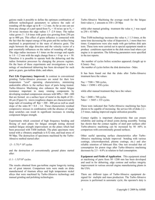
Turbo-Abrasive Machining [TAM] is a mechanical deburring and finishing method originally developed primarily to automate edge finishing procedures on complex rotationally oriented and symmetrical aerospace engine components. Since its inception this method of utilizing fluidized free abrasive materials has facilitated significant reductions in the amount of manual intervention required to deburr large components by these manufacturers. Additionally, the process has also proved to be useful in edge and surface finishing a wide variety of other non-rotational components by incorporating these components into fixturing systems. The advantages of this method go beyond the simple removal or attenuation of burrs. The method is also capable of producing surface conditions at critical edge areas that can contribute to increased service life and functionality of parts that are severely stressed in service. Among these are: (1) the creation of isotropic surfaces. (2) the replacement of positively skewed surface profiles with negative or neutral skews and (3) the development of beneficial compressive stress.
INTRODUCTION
The technology is currently used to deburr and contour the edges of complex parts, and to create isotropic surface finishes essential in finishing many complex parts. Unlike single-point- of-contact machining technologies the technology is relatively simple to control once process parameters for a given part have been developed, and thus enjoys the attributes of reliability repeatability of simpler mechanical (vs. digital feedback) technologies. However, It accomplishes uniform results on very complex parts that often cannot be achieved reliably by other much more complex processes.
The technology involves developing a fluidized bed of media in which the part to be processed is partially immersed while being rotated. A wide variety of differing results may be achieved by varying the process parameters (media, time, rotational speed etc.). Process results can be closely controlled and are programmable, and are totally repeatable, providing unequaled process quality control. The is dry, and involves no chemicals or environmentally unfriendly materials.
One of the distinctive features of TAM that contrasts it with other mechanical or mass media finishing techniques is its more familiar human/machine interface. Operators familiar with PLC or CNC controlled machines for milling, turning or grinding will feel at ease with TAM controls. The major difference between TAM and these methods is the tooling. Unlike the single-point-of-contact tooling used by other machining techniques, the unique TAM abrasive fluidized bed technology makes it possible to machine all the features of rotating components simultaneously. This processing attribute promotes a uniformity of edge/surface conditions and stresses not possible to duplicate with any single-point-of-contact method.
Many of these types parts, because size and shape factors, can not be finished by a mass media technique but need manual](https://image.slidesharecdn.com/asmeturbotechpaper-141006165743-conversion-gate02/85/ASME-Draft-tech-paper-1-320.jpg)
![2 Copyright © 2009 by ASME
intervention for final abrasive finishing. Apart from safety and production line/time considerations, a significant disadvantage of manual deburring is its impact on quality control and assurance procedures that have often been computerized at great cost. The TAM process addresses these problems by automating the final machining and finishing production steps
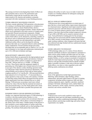
In TAM, fluidized bed technology is utilized to suspend abrasive materials in a specially designed chamber; part surfaces are exposed to and interact with an abrasive fluidized bed on a continuous basis by high-speed rotational or oscilla- tional motion in an entirely dry environment. This combination of abrasive envelopment and high-speed rotational contact can produce important functional surface conditioning effects and deburring and radius formation very rapidly. Because abrasive operations are performed on all features of rotating components simultaneously, the part and feature uniformities achieved are very hard to duplicate by other methods. In addition, sophisticated computer control technologies can be applied to create processes tailored for particular parts. [Figure 1]
Although the abrasive materials used for TAM processing are in some ways similar to grinding and blasting materials, the surface condition produced is unique. One reason for this the multidirectional and rolling nature of abrasive particle contact with part surfaces. These surfaces are characterized by a homogenous, finely blended abrasive pattern developed by the non-perpendicular nature of abrasive attack. There is no perceptible temperature shift in the contact area and finely textured random (isotropic) abrasive pattern is a highly attractive substrate for subsequent coating operations.
TAM Process Elements. Turbo Abrasive Machining (TAM) technology depends on utilizing relatively small free abrasive grains to access intricate part shapes. Unlike blasting or other impact metal finishing methods, the mechanism behind TAM processes utilize a combination of kinematic forces to produce unique and distinctive edge surface finishes on complex and intricate parts which can not be processed with other automated deburring or finishing methods, and usually are processed with manual deburring techniques. These two forces act synergistically and are mutually dependent. They consist of (1) envelopment of the part with abrasive grain suspended in a fluidized bed and (2) interfacing part edges surfaces with abrasive grain by rotational motion of the part.
TAM technology has several advantages in comparison with other mechanical finishing processes. Some of these advantages are:
(a) A High flow of free abrasive grain allows for penetration of abrasive media particles into difficult to access part areas that require edge and surface finish improvement.
(b) Low energy consumption; especially in contrast to pressure blast surface finish
(c) Very simple tooling, processing, and maintenance requirements
(d) A combination of rapid deburring and high rates of metal removal with significant improvements in the physical and mechanical properties of metal surfaces that can enhance surface integrity. These changes include developing: residual compressive stress, surface isotropicization, profile skewness correction, contact rigidity and load bearing ratio improvements
Fluidized Bed Principles. Abrasive grain can be suspended in a work chamber by airflow introduced to the compartment. (Typically, fluidized beds are understood to be contained granular or powder materials that take on the properties of a liquid by introducing a controlled air stream to them. [Figure 2]) The velocity and nature of the particle movement can be expressed mathematically. Collision between particles initiates their rotation, and gives rise to what is referred as the "Magnus effect" the angular velocity of particles contributing to their random and chaotic motion in the fluidized bed. Unlike other edge and surface deburring finishing methods however, the primary energy that produces abrasive effect is not in the abrasive media but rotational motion of part. Experimental analysis has determined the relationship between rotational speed and the depth length (measured here in microns) of abrasive tracks measured on part surfaces. With peripheral speed measured in meters per second, the following table shows the effect of increasing speed on size of abrasive tracks made by 30 mesh grains.
Rotational speed also affects the concentration of abrasive tracks in a given area; the table (TABLE 1) shows the number of abrasive tracks to be found in a square millimeter as speed is increased.
Turbo-Abrasive Machining processes in production often achieve part peripheral speeds in the 20-30 m/s (meter per seconed) range, the value for abrasive tracks in a given square millimeter at this speed can be as high as 500 per mm2 per second. This random pattern of abrasive tracks can be very useful functionally in that the surfaces produced are isotropic in nature.
Metal removal is determined by several factors, including:
the amount of media particle pressure generated on surface, and by the high frequency density of abrasive particles and part surface collisions, which can approach (3-5)*102 1/s*mm2. The calculations carried out by formula (1) have shown that:](https://image.slidesharecdn.com/asmeturbotechpaper-141006165743-conversion-gate02/85/ASME-Draft-tech-paper-2-320.jpg)
![3 Copyright © 2009 by ASME
2
min
1 1
( 1)
3[ ]
k fRp Ea Em
t
V
(1) (1)
where:
- metal fluidity limit;
t - contact time (abrasive and surface);
k - recovery coefficient;
f - abrasive grain density;
Rp - medium radius of grain projection;
Ea, Em - elasticity modula of abrasive grain and metal
the minimum speed of interaction required to produce metal
plastic deformation on components made of structural steel and
ground by abrasive particles with a dimension equal to Dg =
160 - 630μm is Vmin = 1.42 - 0.83 m/sec. Thus media particle
action generated within the fluidized bed at a speed equal to 0.1
- 0.5 m/s is insufficient by itself for effective treatment of metal
surfaces and edges. Additional velocity is required to impart
sufficient intensity to part surface and abrasive grain contact.
The needed velocity can be developed either by rotational
movement or high-frequency oscillation. With the increase of
peripheral speed of a part the force action of the abrasive
pressure (i.e., contact between part features and the fluidized
bed of abrasive grain) on the surface being machined signifi-cantly
increases, thus intensifying metal removal edge
contouring, and surface texture formation. The abrasive
particle pressure value is calculated by formula (2) shows:
Pfd = (k+1) f (1-ε) (Vg+Vp sinθ sinß)2 (2)
where:
1-ε - abrasive grains concentration on a unit volume of fluidized
bed;
Vg - speed of abrasive grain movement;
Vp - speed of a part movement;
f – abrasive grain density
θ-angle inclination of sides of machining/grinding surface
tracks;
ß - angle between the direction of machining track pattern and
part speed vector;
Interaction of the main variables of the (TAM) process, include:
abrasive grain parameters: Dg fluidized bed parameters ε, Vg;
kinematic parameters Vp; surface roughness parameters θ, ß and
mechanical parameters k, of the surface being machined.
Calculations show that with a change of Vp from 10 m/sec to 25
m/sec the values of Pfd are equal to 0.1 - 0.5 MPa. Grain pres-sure
value on a surface being machined varies considerably
depending on the surface orientation in relation to the fluidized
bed of abrasive particles. The optimum surface disposition or
orientation increases the Pfd value 1.2 - 2.6 times; the process
productive capacity and efficiency figures will grow
correspondingly.
A study of track marks made by individual particles illustrates
that the length of scratch marks can grow considerably when the
rotational speed of the part is increased. So with an immobile
part the medium length of scratch Lm when grinding by silicon
carbide particles with a dimension of grain (Dg) = 630μm is
8μm
Thus the transition from processing an immobile part in the
abrasive fluidized bed to processing the part by adding
rotational movement at a peripheral speed rate of 15 m/sec
increases the productive capacity of metal removal volume 200
- 300 times and is equal to 3-7 μm/min depending on physical
and mechanical characteristics of the metal to be machined.
The volume of a single microscratch is determined by
considering a single microscratch as a part of an ellipsoid. The
calculations carried out by formula (4) have shown that:
Where:
l, b, h - average values of length, width, and depth of a
microscratch respectively.
The microscratch depth is determined by the impact theory.
The calculations carried out by formula (5) show:
where
Kh - proportionality coefficient
bm - metal plasticity constant.
The microscratch length is determined as a path passed
by a grain during the contact. The calculations carried
out by formula (6) show:
Where:
Φ - tabulated function in terms of metal plasticity
constant value b(m).
_
The width of a microscratch "b" by modeling the apex angle
with rounding cone based upon the correlation b = 4h.
_ π _ _ _
Vavg. = ─ x l x b x h (4)
8
(2 - Kh) x h x Φ x cosθ
l = ────────────── (6)
Vgr. x sinθ](https://image.slidesharecdn.com/asmeturbotechpaper-141006165743-conversion-gate02/85/ASME-Draft-tech-paper-3-320.jpg)
![4 Copyright © 2009 by ASME
Taking into consideration the obtained formulas for h, l, b, Vavg. and Ngr. the calculations show metal removal intensity as follows:
Table (1) [previous page] shows the data of Qm values, obtained for steel machining by abrasive grain of Al O and size 36 US Mesh.
Surface Finish. In Turbo-Abrasive Machining high-frequency micro-impact interaction of abrasive grains can produce a surface microrelief and outer metal structure that improves part operational and functional properties. TAM processes can achieve surface roughness values Ra 0.2 - 0.4 μm for various steels and alloys, from a starting roughness Ra 3 - 5 μm. The technology makes it possible to develop homogeneous micro- relieved surface textures. After Turbo-Abrasive Machining: the ratio Rmax/Ra equals 6 - 8 while after conventional grinding:
the ratio Rmax/Ra is equal 10 - 12.
Productive Capacity of the Turbo-Abrasive Process. Analysis and experimental investigations of Turbo-Abrasive Machining processes has shown that metal removal intensity - Qm depends on several variables, the principal ones being:
· rotational speed of a part
· machining time
· air discharge
· median size of abrasive particles
· physical and mechanical properties of a machining material
· condition of initial surfaces
· direction of surface micro-unevenness in relation to the vector of part velocity
The abrasive action in the TAM process is very stable. abrasive grain used as the cutting tool nmaintains its ability for extended periods of time. This is because after the initial break-in of the grain, continual impacts grain with part edges and surfaces develop new cutting edges. Abrasive materials of the aluminum oxide group are used in Turbo- Abrasive Machining and also alloyed abrasive materials from the zirconium and chromium-titanium families, with grain affect 160-800 μm, having high impact strength. Productive capacity of Turbo-Abrasive Machining depends on part velocity. The output of metal volume increases 2.8-4.0 times with increasing of velocity speed from Vp = 10 m/sec up to 20 sec. Analysis has shown that metal removal rate decreases with further increasing of part velocity up to Vp = 30 m/sec. This is due to the formation of an air boundary that effectively prevents part surface/abrasive grain collisions. The values Qm increase 2.1 - 2.6 times with media size increasing from 100 μm up to 800 μm. Metal removal rate dependence on rotating part air stream velocity and turbulence is external and proves that air flow increase leads to an air boundary layer volume expansion and consequently, to abrasive particle concentration decrease interacting with a surface unit, and to decrease in abrasive action output. Air flow and abrasive particles are linked by parabolic dependence. While machining continuous aerodynamically well flowed surfaces, an abrasive particle will not lose its cutting ability for a long time; when machining discontinuous surfaces the stability of media particle abrasiveness decreases more rapidly because of intensive frontal impacts with more abruptly shaped part surfaces.
Physical and mechanical properties of the metal alloy being processed influence the quantitative results only, not changing the overall process characteristics. It is estimated that a surface roughness initial direction in relation to a vector of part peripheral speed essentially intensifies both the metal removal rate and metal micro-relief formation.
Deburring and Radius Formation. When machining complex parts, burrs typically appear on all part edges. Mechanical deburring is one of the foremost applications for this tech- nology. TAM processes can provide cost-effective and productive solutions for demanding applications of this type.
One characteristic of Turbo-Abrasive Machining is the high fringe effect (i.e., more intensive machining or finishing of edges and areas closer to the circumference) effective deburring and edge contouring finishing has been performed on this basis. Special examinations have been carried out concerning this technology with regard to deburring and rounding off edges after various machining procedures. Burrs were formed on two types on steel disk samples: after drilling the disk openings 10 mm across; after groove milling; the width is 10 mm in the periphery of disk.
The initial length (bracket) of burrs after drilling reached Lo=0.3 - 0.6mm; after milling Lo = 1.8-2.3 mm. The burrs were removed at rotational speed Vp equal to 5, 10, 20 m/sec. Here aluminum oxide was used, with a grit value Dg = 500; 800 μm. Burr measures were taken by microscope with a measuring error of approximately 3%.
It is established experimentally that burrs are removed completely after being drilled, at Vp = 10 m/sec. If Vp increases up to 20m/sec, time of machining decreases and is equal only 3 min. Burr removal intensity increases 2-4 times in parallel with the rotational speed increase from 10 to 20 m/s in deburring process after drilling, and the grit increasing Dg from 500 to 800 μm - up to 3 times This fact can be explained by the kinetic energy and impact frequency increase. These investigations have shown that Turbo-Abrasive Machining makes it possible to deburr alloys and metal materials of high plasticity and also stainless steel parts. On brass alloys sample burrs were removed at Vp = 20m/sec, but on stainless steel samples the burr removal took 4-6 min. TAM-technology allows simultaneous deburring and rounding off edges. Special investi-
Qm = 33Υ x K³h x (2-K h) x Pfr x (7)
_
cosθ x b (m) x D gr. x (Vgr. + Vp x sinθ x sinβ)](https://image.slidesharecdn.com/asmeturbotechpaper-141006165743-conversion-gate02/85/ASME-Draft-tech-paper-4-320.jpg)
![6 Copyright © 2009 by ASME
only to load and unload the workpieces. The productive capacity of the equipment can be as much 60-80 pcs/h.
The process of Turbo-Abrasive machining proves to be highly effective in solving the following technological problems:
· Deburring after machining operations as well as after stamp- ing;
· Edge break and controlled radius formation;
· Improving surface roughness values to Ra = 0.2 - 0.4 μm [Ra = 1.36 – 10 μin.] for components made of structural and stainless steel, high-temperature, non-ferrous and titanium alloys;
· Substrate preparation before coating;
· Descaling after thermal treatment, carbon deposit removal, etc.
While solving these edge and surface finish problems Turbo- Abrasive machining makes it possible to mechanize and automate labor-intensive manual operations, to increase productivity 3 - 10 times, and to improve stabilize the quality of machined components.
Turbo-Abrasive Machining is being used in edge-finishing turbine and compressor disks, other gas-turbine engine components manufactured of high-temperature and titanium alloys for the aircraft and power industries.
Testing has shown that the fatigue strength limit of disks increases by 26 -38%. when TAM is used as a mechanical finishing process. High efficiency is a distinctive feature of the Turbo-Abrasive machining of gear-wheels in the process of deburring and rounding off the edges after gear-tooth cutting. This technology is also used in the automotive industry for rotor machining of mechanisms for turbo-charging. The new method has been also used for finishing treatment of piston rings. Testing has shown that achieved piston ring surface micro-relief contributes to better lubricant film retention as well as decreasing lubricant consumption. TAM technology can be suc- cessfully applied in machining diamond cut-off wheels and circular saws. It has also been used on agricultural machinery such as shearer comb-cutters for sheep shearing, processed after tooth cutting, 186 comb-cutters being processed simultaneously, with a process time of 10 minutes (i.e. 3 - 5 seconds for each comb-cutter).
All of the above mentioned applications illustrate a wide range of possibilities for Turbo-Abrasive machining, which can be applicable where other technologies can not be used or are less effective. This new method can provide manufacturers the capacity to finish complex parts cost effectively, and develop surface finish characteristics that are more refined and more functionally useful than the manual or conventional methods being currently utilized
Edge/Surface Finishing and Integrity Issues
This technology has been demonstrated to successfully impart compressive stresses into parts in a fashion that is in some ways superior to shot peening. The method is also capable of producing surface conditions at these critical edge areas that contribute to increased service life and functionality of parts that are severely stressed in service. Among these are: (1) the creation of isotropic surfaces. (2) The replacement of positively skewed surface profiles with negative or neutral skews and (3) the development of beneficial compressive stress and the creation of an overall stress equilibrium in parts with a complex feature set.
To elaborate:
The linear characteristics of ground or machined surface patterns can be modified into one in which surface tracks developed by abrasive action have a random (isotropic) non- linear nature, minimizing potential crack propagation points.
The basic character of the surface profile can also be changed from one having a positive skew in which surface peaks were the predominant surface feature to a neutral or negatively skewed surface. These types of plateaued surfaces have much higher bearing load ratios than their positively skewed counterparts, and can increase the service life of components or tools in high wear situations dramatically. This characteristic along with surface isotropicity can improve contact rigidity of mating surfaces, improving seal contact and broadening the surface area of mating surfaces generally.
Almost all common machining and manual finishing methods produce uneven stress hot-spots in machined parts. This occurs because of the rapid rise and fall of temperature on metal surfaces at the tool or wheel point of contact. TAM not only produces beneficial compressive stresses, but also in many cases, where all surfaces and features are effected identically and simultaneously, can promote a stress equilibrium or uniformity through out the entire part. Thus TAM could be looked at as a corrective after process for critical parts that suffer from these machining related surface integrity issues.](https://image.slidesharecdn.com/asmeturbotechpaper-141006165743-conversion-gate02/85/ASME-Draft-tech-paper-6-320.jpg)
![8 Copyright © 2009 by ASME
Significant process characteristics to keep in mind include (1) very rapid cycle times; (2) a high-intensity, small media operation that allows for access into intricate part geometries; (3) a completely dry operation; (4) metal improvement effects; (5) no part-on-pail contact; (6) modest tooling requirements; (7) primarily an external surface preparation method—some simpler interior channels can also be processed; and (8) many types of rotating components can be processed—nonrotational components can also be processed when attached to disklike fixtures.
REFERENCES
Massarsky, M. L., Davidson, D. A., “Turbo-Abrasive Machining, CODEF PROCEEDINGS, 7th International Deburring Conference, Berkeley, CA.: CODEF [Consortium on Deburring and Edge Finishing], University of California at Berkeley, June 2004
Massarsky, M. L., Davidson, D. A.., “Turbo-Abrasive Machining - A New Technology for Metal and Non-Metal Part Finishing”, THE FINISHING LINE, Vol. 18 No. 4, Dearborn MI: Association of Finishing Processes, Society of Manufacturing Engineers, Oct. 30, 2002](https://image.slidesharecdn.com/asmeturbotechpaper-141006165743-conversion-gate02/85/ASME-Draft-tech-paper-8-320.jpg)

This document discusses turbo-abrasive machining (TAM), a mechanical deburring and finishing method that uses a fluidized bed of abrasive materials. TAM was originally developed for aerospace engine components but can also be used for other parts. It provides more uniform results than single-point machining and allows finishing of very complex parts. The document describes the TAM process, which involves rotating a part in an abrasive fluidized bed to remove burrs and contour edges. Process parameters like abrasive size, rotational speed, and time can be varied to achieve different surface finishes and metal removal rates. TAM is capable of deburring complex parts more efficiently than manual methods.


