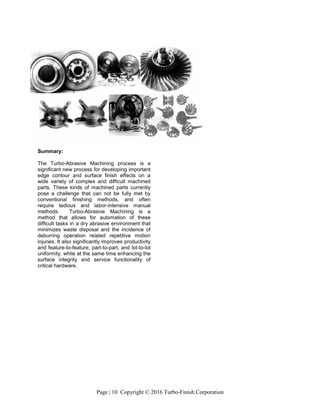
This document describes Turbo-Abrasive Machining (TAM), a mechanical deburring and finishing process that uses fluidized abrasive materials. TAM was originally developed for aerospace engine components but can also finish other rotational and non-rotational parts. TAM provides advantages over manual deburring by automating the finishing process. It produces isotropic surfaces through multidirectional abrasive contact and can improve part properties through residual compressive stress and skewness correction. The process involves suspending abrasive grains in a fluidized bed and rotating parts to interface surfaces and edges with the abrasive grains.
![Page | 1 Copyright © 2016 Turbo-Finish Corporation
TURBO-ABRASIVE MACHINING
Dr. Michael Massarsky
Turbo-Finish Corporation
Barre, Massachusetts, 01005 USA
michael@turbofinish.com
David A. Davidson
Deburring/Surface Finishing Specialist
Spokane, Washington 99205
ddavidson@mgnh.dyndns.org
ABSTRACT
Turbo-Abrasive Machining [TAM] is a
mechanical deburring and finishing method
originally developed primarily to automate edge
finishing procedures on complex rotationally
oriented and symmetrical aerospace engine
components. Since its inception this method of
utilizing fluidized free abrasive materials has
facilitated significant reductions in the amount of
manual intervention required to deburr large
components by these manufacturers.
Additionally, the process has also proved to be
useful in edge and surface finishing a wide
variety of other non-rotational components by
incorporating these components into fixturing
systems. The advantages of this method go
beyond the simple removal or attenuation of
burrs. The method is also capable of producing
surface conditions at critical edge areas that can
contribute to increased service life and
functionality of parts that are severely stressed
in service. Among these are: (1) the creation of
isotropic surfaces. (2) the replacement of
positively skewed surface profiles with negative
or neutral skews and (3) the development of
beneficial compressive stress.
One of the distinctive features of TAM that
contrasts it with other mechanical or mass
media finishing techniques is its more familiar
human/machine interface. Operators familiar
with PLC or CNC controlled machines for
milling, turning or grinding will feel at ease with
TAM controls. The major difference between
TAM and these methods is the tooling. Unlike
the single-point-of-contact tooling used by other
machining techniques, the unique TAM abrasive
FIGURE 1 - MODEL TF-522 TURBO-ABRASIVE
MACHINING CENTER FOR DEBURRING AND EDGE
CONTOURING TURBINE DISKS UP TO 500MM IN
DIAMETER.
Dr. Michael L Massarsky
TURBOFINISH CORPORATION
P. O. Box 344
Barre, MA 01005 USA
phone; 917.518.8205
e-mail: michael@turbofinish.com
David A. Davidson
SME Technical Community Network,
Colville, WA 99114 USA
phone: 509.230.6821
e-mail: dryfinish@gmail.com
Turbo-Abrasive Machining: Dry, High-Speed Automated
Isotropic Finishing of Turbine Rotating Parts
INTRODUCTION: Turbo-Finish technology (also referred to as Turbo-Abrasive Machining) is a dry,
high-speed spindle finishing process that utilizes abrasive fluidized bed technology, and high speed part
rotation to develop extremely rapid and uniform edge and surface conditioning on aerospace, automotive
and industrial parts. Polishing, deburring and edge radiusing are accomplished anywhere that the media
can access. This finishing technology can develop isotropic surface finishes s while developing consistent
round edges on any exposed sharp edged features.
Many critical machined parts and components have burr and edge conditions that require substantial
deburring and edge and surface finishing prior to being ready for final assembly and introduction into
service. Burrs, sharp edges, and rough surfaces must be replaced with radiused edges and smoother
isotropic surfaces to prevent problems associated with premature fatigue or wear failure of the parts
while in service. Stress risers must also be eliminated and replaced with a compressive stress condition if
premature part failure is to be avoided. This is especially true in the aerospace and other industries
whose parts are subjected to repeated stress in operation.](https://image.slidesharecdn.com/2016tamtechpaper-170704173612/85/2016-tam-tech-paper-1-320.jpg)
![Page | 1 Copyright © 2016 Turbo-Finish Corporation
TURBO-ABRASIVE MACHINING
Dr. Michael Massarsky
Turbo-Finish Corporation
Barre, Massachusetts, 01005 USA
michael@turbofinish.com
David A. Davidson
Deburring/Surface Finishing Specialist
Spokane, Washington 99205
ddavidson@mgnh.dyndns.org
ABSTRACT
Turbo-Abrasive Machining [TAM] is a
mechanical deburring and finishing method
originally developed primarily to automate edge
finishing procedures on complex rotationally
oriented and symmetrical aerospace engine
components. Since its inception this method of
utilizing fluidized free abrasive materials has
facilitated significant reductions in the amount of
manual intervention required to deburr large
components by these manufacturers.
Additionally, the process has also proved to be
useful in edge and surface finishing a wide
variety of other non-rotational components by
incorporating these components into fixturing
systems. The advantages of this method go
beyond the simple removal or attenuation of
burrs. The method is also capable of producing
surface conditions at critical edge areas that can
contribute to increased service life and
functionality of parts that are severely stressed
in service. Among these are: (1) the creation of
isotropic surfaces. (2) the replacement of
positively skewed surface profiles with negative
or neutral skews and (3) the development of
beneficial compressive stress.
One of the distinctive features of TAM that
contrasts it with other mechanical or mass
media finishing techniques is its more familiar
human/machine interface. Operators familiar
with PLC or CNC controlled machines for
milling, turning or grinding will feel at ease with
TAM controls. The major difference between
TAM and these methods is the tooling. Unlike
the single-point-of-contact tooling used by other
machining techniques, the unique TAM abrasive
FIGURE 1 - MODEL TF-522 TURBO-ABRASIVE
MACHINING CENTER FOR DEBURRING AND EDGE
CONTOURING TURBINE DISKS UP TO 500MM IN
DIAMETER.
Dr. Michael L Massarsky
TURBOFINISH CORPORATION
P. O. Box 344
Barre, MA 01005 USA
phone; 917.518.8205
e-mail: michael@turbofinish.com
David A. Davidson
SME Technical Community Network,
Colville, WA 99114 USA
phone: 509.230.6821
e-mail: dryfinish@gmail.com
Turbo-Abrasive Machining: Dry, High-Speed Automated
Isotropic Finishing of Turbine Rotating Parts
INTRODUCTION: Turbo-Finish technology (also referred to as Turbo-Abrasive Machining) is a dry,
high-speed spindle finishing process that utilizes abrasive fluidized bed technology, and high speed part
rotation to develop extremely rapid and uniform edge and surface conditioning on aerospace, automotive
and industrial parts. Polishing, deburring and edge radiusing are accomplished anywhere that the media
can access. This finishing technology can develop isotropic surface finishes s while developing consistent
round edges on any exposed sharp edged features.
Many critical machined parts and components have burr and edge conditions that require substantial
deburring and edge and surface finishing prior to being ready for final assembly and introduction into
service. Burrs, sharp edges, and rough surfaces must be replaced with radiused edges and smoother
isotropic surfaces to prevent problems associated with premature fatigue or wear failure of the parts
while in service. Stress risers must also be eliminated and replaced with a compressive stress condition if
premature part failure is to be avoided. This is especially true in the aerospace and other industries
whose parts are subjected to repeated stress in operation.](https://image.slidesharecdn.com/2016tamtechpaper-170704173612/75/2016-tam-tech-paper-1-2048.jpg)
![Page | 2 Copyright © 2016 Turbo-Finish Corporation
fluidized bed technology makes it possible to
machine all the features of rotating components
simultaneously. This processing attribute
promotes a uniformity of edge/surface conditions
and stresses not possible to duplicate with any
single-point-of-contact method.
Turbo Abrasive Machining (TAM) is a new
process for deburring, edge contouring and
surface conditioning complex rotating machined
parts. Many of these types of parts, because of
size and shape factors, can not be finished by a
mass media technique but need manual
intervention for final abrasive finishing. Apart
from safety and production line/time considera-
tions, a significant disadvantage of manual
deburring is its impact on quality control and
assurance procedures that have often been
computerized at great cost. The TAM process
addresses these problems by automating the
final machining and finishing production steps.
In TAM, fluidized bed technology is utilized to
suspend abrasive materials in a specially
designed chamber; part surfaces are exposed to
and interact with an abrasive fluidized bed on a
continuous basis by high-speed rotational or
oscillational motion in an entirely dry environ-
ment. This combination of abrasive envelopment
and high-speed rotational contact can produce
important functional surface conditioning effects
and deburring and radius formation very rapidly.
Because abrasive operations are performed on
all features of rotating components simultane-
ously, the part and feature uniformities achieved
are very hard to duplicate by other methods. In
addition, sophisticated computer
control technologies can be
applied to create processes
tailored for particular parts.
[Figure 1]
Although the abrasive materials
used for TAM processing are in
some ways similar to grinding
and blasting materials, the
surface condition produced is
unique. One reason for this is
the multidirectional and rolling
nature of abrasive particle
contact with part surfaces. These
surfaces are characterized by a
homogenous, finely blended
abrasive pattern developed by
the non-perpendicular nature of
abrasive attack. There is no
perceptible temperature shift in the contact area
and the finely textured random (isotropic)
abrasive pattern is a highly attractive substrate
for subsequent coating operations.
TAM Process Elements. Turbo Abrasive
Machining (TAM) technology depends on
utilizing relatively small free abrasive grains to
access intricate part shapes. Unlike blasting or
other impact metal finishing methods, the
mechanism behind TAM processes utilize a
combination of kinematic forces to produce
unique and distinctive edge and surface finishes
on complex and intricate parts which can not be
processed with other automated deburring or
finishing methods, and usually are processed
with manual deburring techniques. These two
forces act synergistically and are mutually
dependent. They consist of (1) envelopment of
the part with abrasive grain suspended in a
fluidized bed and (2) interfacing part edges and
surfaces with abrasive grain by rotational motion
of the part.
TAM technology has several advantages in
comparison with other mechanical finishing
processes. Some of these advantages are:
A High flow of free abrasive grain allows
for penetration of abrasive media
particles into difficult to access part
areas that require edge and surface
finish improvement.
FIGURE 2 - CRITICAL AIR FLOW SPEED (VELOCITY)
V1 2V V2](https://image.slidesharecdn.com/2016tamtechpaper-170704173612/85/2016-tam-tech-paper-2-320.jpg)
![Page | 3 Copyright © 2016 Turbo-Finish Corporation
Low energy consumption; especially in
contrast to pressure blast surface
finishing.
Very simple tooling, processing, and
maintenance requirements;
Combination of rapid deburring and high rates of
metal removal with significant improvements in
the physical and mechanical properties of metal
surfaces that can enhance surface integrity.
These changes include developing: residual
compressive stress, surface isotropicization,
surface profile skewness correction, contact
rigidity and load bearing ratio improvements.
Fluidized Bed Principles. Abrasive grain can
be suspended in a work chamber by airflow
introduced to the compartment. (Typically,
fluidized beds are understood to be contained
granular or powder materials that take on the
properties of a liquid by introducing a controlled
air stream to them. [Figure 2]) The velocity and
nature of the particle movement can be
expressed mathematically. Collision between
particles initiates their rotation, and gives rise to
what is referred to as the "Magnus effect" the
angular velocity of particles contributing to their
random and chaotic motion in the fluidized bed.
Unlike other deburring and finishing methods
however, the primary energy that produces the
abrasive effect is not in the abrasive media but
in the rotational motion of the part. Experimental
analysis has determined the relationship
between rotational speed and the depth and
length (measured here in microns) of abrasive
tracks measured on part surfaces. With
peripheral speed measured in meters per
second, the following table shows the effect of
increasing speed on the size of abrasive tracks
made by 30 mesh grains.
Rotational speed also affects the concentration
of abrasive tracks in a given area; the table
(TABLE 1) shows the number of abrasive tracks
to be found in a square millimeter as speed is
increased.
Turbo-Abrasive Machining processes in
production often achieve part peripheral speeds
in the 20-30 m/s (meter per seconed) range, the
value for abrasive tracks in a given square
millimeter at this speed can be as high as 500
per mm2 per second. This random pattern of
abrasive tracks can be very useful functionally in
that the surfaces produced are isotropic in
nature.
Metal removal is determined by several factors,
including:
the amount of media particle pressure generated
on the surface, and by the high frequency and
density of abrasive particles and part surface
collisions, which can approach (3-5)*102
1/s*mm2. The calculations carried out by formula
(1) have shown that:
2
min
11
)1(
][3
map EEfRk
t
V
(1)
where:
- metal fluidity limit;
t - contact time (abrasive and surface);
k - recovery coefficient;
FIGURE 3 - DOVETAIL SLOT FEATURE ON TURBINE
DISK WITH SHARP EDGES PRIOR TO TAM
PROCESSING
FIGURE 4 - AFTER TAM PROCESSING, SHARP EDGES HAVE
BEEN REPLACED WITH POLISHED EDGE CONTOURED. TWO
TAM PROCESSES WITH SEQUENTIALLY FINER ABRASIVE
MATERIAL WERE USED.](https://image.slidesharecdn.com/2016tamtechpaper-170704173612/85/2016-tam-tech-paper-3-320.jpg)
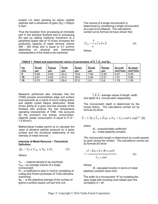
![Page | 6 Copyright © 2016 Turbo-Finish Corporation
Taking into consideration the obtained formulas
for h, l, b, Vavg. and Ngr. the calculations show the
metal removal intensity as follows:
Table (1) [previous page] shows the data of Qm
values, obtained for steel machining by abrasive
grain of Al O and size 36 US Mesh.
Surface Finish. In Turbo-Abrasive Machining
high-frequency micro-impact interaction of
abrasive grains
can produce a
surface micro-
relief and outer
metal structure
that improves
part operational
and functional
properties. TAM
processes can
achieve surface
roughness
values Ra 0.2 -
0.4 μm for
various steels
and alloys, from
a starting
roughness Ra 3
- 5 μm. The
technology
makes it
possible to
develop homogeneous micro-relieved surface
textures. After Turbo-Abrasive Machining: the
ratio Rmax/Ra equals 6 - 8 while after
conventional grinding:
the ratio Rmax/Ra is equal 10 - 12.
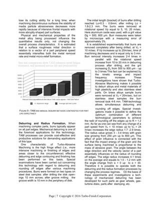
Productive Capacity of the Turbo-Abrasive
Process. Analysis and experimental
investigations of Turbo-Abrasive Machining
processes has shown that metal removal
intensity - Qm depends on several variables, the
principal ones being:
· rotational speed of a part
· machining time
· air discharge
· median size of abrasive particles
· physical and mechanical properties of a
machining material ~ condition of initial
surfaces
· direction of surface micro-unevenness in
relation to the vector of part velocity
The abrasive action
in the TAM process
is very stable. The
abrasive grain used
as the cutting tool
nmaintains its
cutting ability for
extended periods of
time. This is
because after the
initial break-in of
the grain, the
continual impacts of
grain with part
edges and surfaces
develop new cutting
edges. Abrasive
materials of the
aluminum oxide
group are used in
Turbo-Abrasive
Machining and also
alloyed abrasive
materials from the
zirconium and chromium-titanium families, with
grain affect 160-800 μm, having high impact
strength. Productive capacity of Turbo-Abra-
sive machining depends on part velocity. The
output of metal volume increases 2.8-4.0 times
with increasing of velocity speed from Vp = 10
m/sec up to Vp = 20 m/sec. Analysis has shown
that metal removal rate decreases with further
increasing of part velocity up to Vp = 30 m/sec.
This is due to the formation of an air boundary
that effectively prevents part surface/abrasive
grain collisions. The values Qm increase 2.1 -
2.6 times with media size increasing from 100
μm up to 800 μm. Metal removal rate
dependence on rotating part air stream velocity
and turbulence is external and proves that air
flow increase leads to an air boundary layer
volume expansion and consequently, to
abrasive particle concentration decrease
interacting with a surface unit, and to a decrease
in abrasive action output. Air flow and abrasive
particles are linked by parabolic dependence.
While machining continuous aerodynamically
well flowed surfaces, an abrasive particle will not
Qm = 33Υ x K³h x (2-K h) x Pfr x (7)
_ _
cosθ x b (m) x D gr. x (Vgr. + Vp x sinθ x sinβ)
FIGURE 7 - THIS
PHOTOGRAPH AT HIGH
MAGNIFICATION SHOWS THE
SURFACE [PROFILE OF AN AS
GROUND SURFACE. THE IS A
POSITIVELY SKEWED SURFACE
WITH SURFACE PEAKS THE
PREDOMINANT
CHARACTERISTIC.
FIGURE 8 – THIS HIGHLY
MAGNIFIED PHOTOGRAPH
SHOWS SURFACE
CHARACTERISTICS OFTER
TAM PROCESSING. NOTE
THE RANDOM NATURE OF
THE SURFACE PATTERN
TYPICAL OF ISOTROPIC
SURFACES](https://image.slidesharecdn.com/2016tamtechpaper-170704173612/85/2016-tam-tech-paper-6-320.jpg)
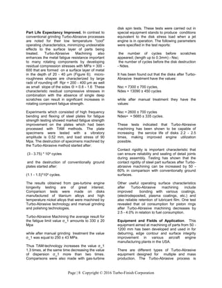
![Page | 9 Copyright © 2016 Turbo-Finish Corporation
performed in automatic cycle; the operator's duty
is only to load and unload the workpieces. The
productive capacity of the equipment can be as
much as 60-80 pcs/h.
The process of Turbo-Abrasive machining
proves to be highly effective in solving the
following technological problems:
· Deburring after machining operations as well
as after stamping;
· Edge break and controlled radius formation;
· Improving surface roughness values to Ra =
0.2 - 0.4 μm [Ra = 1.36 – 10 μin.] for compo-
nents made of structural and stainless steel,
high-temperature, non-ferrous and titanium
alloys;
· Substrate preparation before coating;
· Descaling after thermal treatment, carbon
deposit removal, etc.
While solving these edge and surface finish
problems Turbo-Abrasive machining makes it
possible to mechanize and automate labor-
intensive manual operations, to increase
productivity 3 - 10 times, and to improve and
stabilize the quality of machined components.
Turbo-Abrasive Machining is being used in
edge-finishing turbine and compressor disks,
and other gas-turbine engine components
manufactured of high-temperature and titanium
alloys for the aircraft and power industries.
Testing has shown that the fatigue strength limit
of disks increases by 26 -38%. when TAM is
used as a mechanical finishing process. High
efficiency is a distinctive feature of the Turbo-
Abrasive machining of gear-wheels in the
process of deburring and rounding off the edges
after gear-tooth cutting. This technology is also
used in the automotive industry for rotor
machining of mechanisms for turbo-charging.
The new method has been also used for
finishing treatment of piston rings. Testing has
shown that achieved piston ring surface micro-
relief contributes to better lubricant film retention
as well as decreasing lubricant consumption.
TAM technology can be successfully applied in
machining diamond cut-off wheels and circular
saws. It has also been used on agricultural
machinery such as shearer comb-cutters for
sheep shearing, processed after tooth cutting,
186 comb-cutters being processed
simultaneously, with a process time of 10
minutes (i.e. 3 - 5 seconds for each comb-
cutter).
All of the above mentioned applications
illustrate a wide range of possibilities for Turbo-
Abrasive machining, which can be applicable
where other technologies can not be used or are
less effective. This new method can provide
manufacturers the capacity to finish complex
parts cost effectively, and develop surface finish
characteristics that are more refined and more
functionally useful than the manual or
conventional methods being currently utilized.
FIGURE 11 – TYPICAL EDGE CONTOUR ON
SIMILAR FEATURES AFTER TAM PROCESSING.
FIGURE 10 - BURR AND EDGE CONDITION PRIOR TO TAM
PROCESSING](https://image.slidesharecdn.com/2016tamtechpaper-170704173612/85/2016-tam-tech-paper-9-320.jpg)