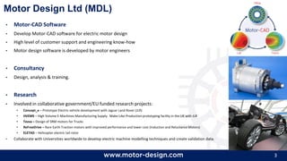
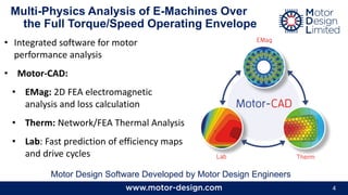
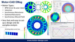
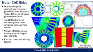
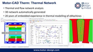
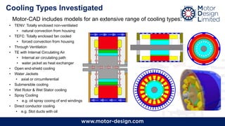
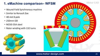
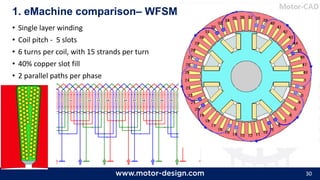
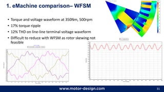
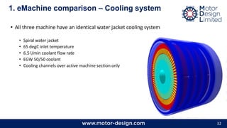
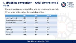
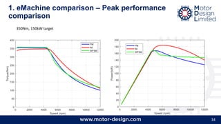
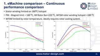
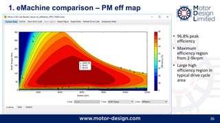
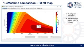
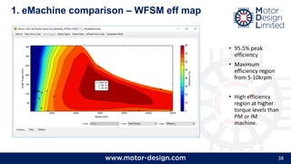
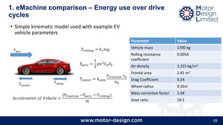
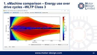
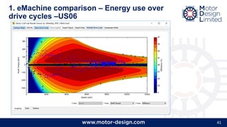
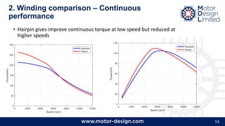
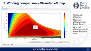
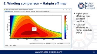
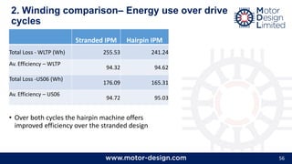
Electric Motor Design:
Trade-Off Analysis
Dr James Goss
CWIEME 2018
2
Topics:
• Introduction
• Motor Design Ltd (MDL)
• Introduction to Power Traction and Electric Vehicles
• Trade-off Analysis for a BEV traction application
• Comparison of PM, IM and Sync traction machine types
• Comparison of hairpin vs stranded windings for a PM machine
• Comparison of water jacket, internal air and oil spray cooling
3
Motor Design Ltd (MDL)
• Motor-CAD Software
• Develop Motor-CAD software for electric motor design
• High level of customer support and engineering know-how
• Motor design software is developed by motor engineers
• Consultancy
• Design, analysis & training.
• Research
• Involved in collaborative government/EU funded research projects:
• Concept_e – Prototype Electric vehicle development with Jaguar Land Rover (JLR)
• HVEMS – High Volume E-Machines Manufacturing Supply. Make-Like-Production prototyping facility in the UK with JLR
• Tevva – Design of SRM motors for Trucks
• ReFreeDrive – Rare Earth Traction motors with improved performance and lower cost (Induction and Reluctance Motors)
• ELETAD – Helicopter electric tail rotor
• Collaborate with Universities worldwide to develop electric machine modelling techniques and create validation data.
4
• Integrated software for motor
performance analysis
• Motor-CAD:
• EMag: 2D FEA electromagnetic
analysis and loss calculation
• Therm: Network/FEA Thermal Analysis
• Lab: Fast prediction of efficiency maps
and drive cycles
Multi-Physics Analysis of E-Machines Over
the Full Torque/Speed Operating Envelope
Motor Design Software Developed by Motor Design Engineers
5
Motor-CAD EMag
• Motor Types:
• BPM (inner & outer rotor)
• Induction
• Synchronous Reluctance
• Switched Reluctance
• Synchronous Wound Field
• Very fast and easy to set-
up a design and do
complex analysis
Winding eddy current loss
6
Motor-CAD EMag
• Extensive range of
parametrised templates
geometries with additional
flexible DXF or script based
geometry definition
• Fast 2D FEA transient
electromagnetic solver
combined with analytical
models
• Analysis of losses inc. AC
winding losses & magnet
eddy currents
• Standard or custom winding
designs
Rotor Geometry
Created using Script
Rotor Geometry
Created using DXF
Motor-CAD Therm: Thermal Network
• Thermal and flow network analysis
• 3D network automatically generated
• 20 years of embedded experience in thermal modelling of eMachines
Cooling Types Investigated
• Motor-CAD includes models for an extensive range of cooling types:
• TENV: Totally enclosed non-ventilated
• natural convection from housing
• TEFC: Totally enclosed fan cooled
• forced convection from housing
• Through Ventilation
• TE with Internal Circulating Air
• Internal air circulating path
• water jacket as heat exchanger
• Open end-shield cooling
• Water Jackets
• axial or circumferential
• Submersible cooling
• Wet Rotor & Wet Stator cooling
• Spray Cooling
• e.g. oil spray cooing of end windings
• Direct conductor cooling
• e.g. Slot ducts with oil
Steady-State & Transient Thermal Analysis
• We can calculate the steady-state or transient thermal
performance
• Temperature rise over a complex duty cycle can be solved
rapidly and analysed iteratively during the design process
Thermal Transient
Graphs
Steady-State Temperatures and Power Flow
• Facilitates very fast and accurate calculation of the motor electromagnetic and thermal
performance over the full torque/speed envelope by use of intelligent loss algorithms
• Suited to applications such as traction applications that have complex duty cycle loads
• Automated calculation of optimum phase advance angle for maximum torque/amp or
maximum efficiency control
Motor-CAD Lab: Virtual Testing Laboratory
Efficiency map with drive cycle overlaid Loss v Time calculated from
efficiency map to be input into
thermal model
Temperature v Time for a particular
drive cycle
Virtual testing including fast calculation of Efficiency Maps/Losses and Duty Cycle Analysis
Motor-CAD Lab: Thermally Limited Envelope
• Co-simulation between electromagnetic model
(via flux linkage and loss maps) with thermal
model gives an accurate prediction of the
continuous torque envelope
• Maximum torque at different speeds for a
limited winding and rotor temperature
• We can also calculate the peak torque envelope
• Thermal transient for a set amount of time
that gives a certain maximum winding
temperature
This is output matches how electric motors are typically
specified. It is very useful to compare these curves for
different design variations.
Torque is limited
here on maximum
winding temperature
Torque is limited here on
maximum rotor/magnet
temperature
Transient operation
region
12
Dynamic Operation
• The operation of these machines is very dynamic and consideration of performance across
the full torque/speed operating envelope is required
• Modelling tools need to support this, Motor-CAD is a unique solution on the market for this
type of analysis
• It allow machine efficiency to be optimised over standard operating cycles and sized for a
worst-case cycle, giving minimum system size and cost
Vehicle
Speed Profile
Motor/Generator: Time
vs Torque vs Speed
Motor/Generator:
Loss vs Time
Motor/Generator:
Temperature Vs Time
Motor-CAD: Systems Engineering and workflow
➢ Interaction between other powertrain components is
handled through coupling with other specialist tools
➢ Combined NVH response of motor and gearbox using Motor-CAD and Romax
designer
➢ Combined inverter and motor behaviour through model export to Simulink
Simscape
➢ Vehicle thermal system behaviour analysed through co-simulation with GT-
Suite
➢ Partnership with Ansys provides coupling to high power numerical
simulation:
➢ 3D FEA for analysis of end-effects with Ansys Maxwell
➢ CFD for analysis of heat transfer due to fluid flow with Fluent
➢ Mechanical stress and vibration analysis with Ansys Mechanical
Motor-CAD Links to ANSYS for Improved Design Workflow
Concept Design to System Validation
Design Tool
for electrical
machines
Advanced Magnetics Modeling
Maxwell 2D & 3D
Lab
Efficient Motor Design Toolkit
Motor-CAD
EmagThermal
NVH, Cooling
Mechanical & CFD
Control logic, software
System Validation
3D Physical Validation
Concept Design System Validation
Lab
Design Analysis Operation
15
Variation in Motor Design Configurations
• Many motor types and topologies have been
developed recently:
• As seen by the wide range of EV traction
motor designs on the market
• Motor-CAD easy to use interface and fast
calculation times are very useful for designers
to evaluate different motor design concepts
Examples of Traction Motors in Motor-CAD
• Can model all common EV traction motors types in Motor-CAD
• Leaf, Tesla, Prius, Accord, Volt, i3, Zoe, ….
• Different winding types
• Distributed, Tooth Wound, Bar/Hairpin, Litz …
• BPM, Induction, Wound Field, Reluctance, ….
• Different Cooling types
• Air Cooled, Water Jacket, Oil Spray, …..
TESLA LEAF PRIUS ACCORD
i3
17
Performance Prediction for Tesla Model S Motor
• Data from teardown analysis of the Tesla Model S electric motor
• Copper rotor induction motor with potted end windings and water
cooled stator and rotor
18
Performance Prediction for Nissan LEAF Motor
• Using published
teardown data for
Nissan LEAF motor
• Developed models to
validate &
demonstrate software
tools for modelling
traction applications
19
Introduction to trade-off study
• Development of an EV powertrain is a complex systems problem
• Achieving an optimal system design requires evaluation of many different
concepts and topologies as well as detailed understanding of the system
interactions
• These interactions are typically cross specialism or discipline, involve different
teams and often require multi-physics analysis
• Design and simulation tools are crucial to evaluating different design
topologies as well as identifying and understanding important system
interactions
20
➢Trade-off Analysis for a BEV traction
application
1. Comparison of PM, IM and Sync traction machine types
- Same outer diameter
- Same peak performance req.
- Different axial lengths
- Same water jacket cooling
2. Comparison of hairpin vs stranded windings for a PM machine
- Same active dimensions & cooling
- Different slot fill factor & winding losses
3. Comparison of water jacket, internal air and oil spray cooling
-Same active dimensions and electromagnetic design
21
• Peak Torque = 350Nm
• Peak Power = 150kW
• Vdc = 400Vdc
• Max Current = 500Arms
• Maximum speed = 12,000rpm
• Stator OD = 250mm
Specification
22
• Brushless PM machine
• 48 slot 8 pole IPM
• Double layer magnet – similar to BMW i3
• N42UH magnet
• M250-35A steel
• 250mm OD
• Multi-stranded stator windings
• Step skewed rotor
1. eMachine comparison– PM
23
• Single layer winding
• Coil pitch - 5 slots
• 6 turns per coil, with 15 strands per turn
• 40% copper slot fill
• 2 parallel paths per phase
1. eMachine comparison– PM
24
BEMF - 500rpm
• Back emf waveform at
500rpm
• 3 slices combine to give
sinusoidal waveform
25
Torque - 350Nm
• Torque waveform at
350Nm
• 3 slices combine to
minimise torque ripple
• Torque ripple = 4.4%
26
• Induction machine
• 72 slot 84 bar
• 6 pole
• Copper rotor
• M250-35A
• 250mm OD
• Multi-stranded winding
• 5⁰ mech rotor bar skew
1. eMachine comparison– IM
27
• Single layer winding
• Coil pitch - 11 slots
• 3 turns per coil, with 15 strands per turn
• 40% copper slot fill
• 2 parallel paths per phase
1. eMachine comparison– IM
28
• Torque waveform, flux density and rotor bar eddy
current density at 350Nm
• Solved with full transient solver inc. rotor rotation
(e.g. space harmonics)
• 17% ripple but rotor bar skew isn’t account for in
this example
1. eMachine comparison– IM
29
1. eMachine comparison– WFSM
• Wound Field Synchronous machine
• Similar to Renault Zoe
• 48 slot 8 pole
• 250mm OD
• M250-35A steel
• Rotor winding with 132 turns
30
• Single layer winding
• Coil pitch - 5 slots
• 6 turns per coil, with 15 strands per turn
• 40% copper slot fill
• 2 parallel paths per phase
1. eMachine comparison– WFSM
31
• Torque and voltage waveform at 350Nm, 500rpm
• 17% torque ripple
• 12% THD on line-line terminal voltage waveform
• Difficult to reduce with WFSM as rotor skewing not
feasible
1. eMachine comparison– WFSM
32
• All three machine have an identical water jacket cooling system
• Spiral water jacket
• 65 degC inlet temperature
• 6.5 l/min coolant flow rate
• EGW 50/50 coolant
• Cooling channels over active machine section only
1. eMachine comparison – Cooling system
33
• All machines designed for equivalent peak performance characteristic
• IM has longer end windings due to winding pattern
1. eMachine comparison – Axial dimensions &
mass
PM IM WFSM
Active length (mm) 100 120 120
End winding overhang (mm) 30 40 30
Total length (mm) 160 200 180
Steel (kg 26.1 33.4 28.17
Copper (kg) 5.05 13.7 8.5
Magnet (kg) 2.05 0 0
Total (kg) 33.2 47 36.7
34
1. eMachine comparison – Peak performance
comparison
350Nm, 150kW target
35
1. eMachine comparison – Continuous
performance comparison
• Stator winding limited on 180⁰C hotspot
• PM - Magnet limit = 160 ⁰C, IM Rotor Bar=220 ⁰C, WFSM rotor winding hotspot =180 ⁰C
• WFSM limited by rotor temperature, ideally requires rotor cooling system.
36
1. eMachine comparison – PM eff map
• 96.8% peak
efficiency
• Maximum
efficiency region
from 2-9krpm
• Large high
efficiency region in
typical drive cycle
area
37
1. eMachine comparison – IM eff map
• 95.5% peak
efficiency
• High efficiency
region from 7-
12krpm
38
1. eMachine comparison – WFSM eff map
• 95.5% peak
efficiency
• Maximum
efficiency region
from 5-10krpm
• High efficiency
region at higher
torque levels than
PM or IM
machine.
39
• Simple kinematic model used with example EV
vehicle parameters
1. eMachine comparison – Energy use over drive
cycles
Frolling
Faero
Ftraction
𝑇 𝑚𝑜𝑡𝑜𝑟 = 𝑘 𝑑𝑒𝑚
𝐹𝑡𝑟𝑎𝑐𝑡𝑖𝑜𝑛. 𝑟ω
𝑛 𝑑
𝐴𝑐𝑐𝑒𝑙𝑒𝑟𝑎𝑡𝑖𝑜𝑛 𝑜𝑓 𝑉𝑒ℎ𝑖𝑐𝑙𝑒 =
(𝐹𝑡𝑟𝑎𝑐𝑡𝑖𝑜𝑛 −𝐹𝑎𝑒𝑟𝑜 − 𝐹𝑟𝑜𝑙𝑙𝑖𝑛𝑔)
𝑚
𝐹𝑟𝑜𝑙𝑙𝑖𝑛𝑔 = 𝑘 𝑟 𝑚𝑔
𝐹𝑎𝑒𝑟𝑜 =
1
2
𝑝𝑣2
𝐶 𝑑 𝐴 𝑓
Parameter Value
Vehicle mass 1700 kg
Rolling resistance
coefficient
0.0054
Air density 1.225 kg/m3
Frontal area 2.81 m2
Drag Coefficient 0.24
Wheel radius 0.35m
Mass correction factor 1.04
Gear ratio 10:1
40
1. eMachine comparison – Energy use over
drive cycles –WLTP Class 3
41
1. eMachine comparison – Energy use over
drive cycles –US06
42
1. eMachine comparison – Energy use over
drive cycles
IPM IM WFSM
Total Loss - WLTP (Wh) 255.53 310.25 312.62
Av. Efficiency – WLTP
94.32 93.17 92.79
Total Loss -US06 (Wh)
176.09 223.57 214.9
Av. Efficiency – US06
94.72 93.39 93.44
• Reduced efficiency = reduced range/increased battery size
• PM gives best efficiency over cycle
43
1. eMachine comparison – Dual motor?
• Premium EVs are tending to adopt a dual motor
topology, one on each axle.
• For example, Jaguar i-pace, Audi e-tron, Tesla Model
3/S/X.
• Could optimal efficiency and energy use be achieved
by using the PM machine on the rear axle and IM
machine on the front or vice versa?
• The IM machine could be optimised for higher
speed, low torque cruising. While the PM machine
could work well for low-medium speed operation
and high torque operation.
• Tesla have announced a version of the model 3 with
this set-up
44
1. eMachine comparison – Summary
• PM machine offers improved efficiency and reduced
mass/volume at higher cost
• Systems aspects, such as improved range or reduced battery
mass for the same, with increased efficiency may mean that the
PM motor gives the lowest overall system cost
• However the PM and IM machines show improved efficiencies at
different areas of the map and if a dual motor configuration is
used this could be advantageous.
• The WFSM has similar performance to the IM however the
thermal performance is very constrained on rotor temperature
and really some rotor cooling system is required in this example.
45
2. Winding comparison
• Hairpin windings are growing in
popularity and are used in the
Gen2 GM volt and Toyota Prius
MY17
• They offer advantages in
manufacturing cost and
performance repeatability
• However the also have some
disadvantages
• The next section of the
comparison looks at hairpin vs.
stranded windings
GM Volt
Toyota Prius MY17
46
• Brushless PM machine
• 48 slot 8 pole IPM
• Double layer magnet – similar to BMW i3
• N42UH magnet
• M250-35A steel
• 250mm OD
• Multi-stranded stator windings
• Step skewed rotor
• 100mm axial length
2. Winding comparison – Stranded
PM machine
47
• Single layer winding
• Coil pitch - 5 slots
• 6 turns per coil, with 15 strands per turn
• 40% copper slot fill
• 2 parallel paths per phase
2. Winding comparison – Stranded
PM machine
48
• Brushless PM machine
• 48 slot 8 pole IPM
• Double layer magnet – similar to BMW i3
• N42UH magnet
• M250-35A steel
• 250mm OD
• Multi-stranded stator windings
• Step skewed rotor
• 100mm axial length
2. Winding comparison – Hairpin
PM machine
49
• Single layer winding
• Coil pitch - 5 slots
• 6 turns per coil
• 2 parallel paths per phase
2. Winding comparison – Hairpin
PM machine
50
2. Winding comparison – Hairpin PM machine
• CSA of the slot is slightly lower with the
hairpin
• Slot fill factor is higher giving lower resistance
• Higher AC loss but lower DC loss with hairpin
Stranded Hairpin
Copper Fill Factor 0.4 0.65
Slot Cross Sectional Area (mm2) 145.7 130.9
Conductor Cross Sectional Area (mm2) 58.29 85.14
Phase resistance (Ω) 0.0113 0.00773
DC winding loss @ 100Nm, 8000rpm 1239 873.6
AC winding loss @ 100Nm, 8000rpm 596.4 1069
Combined winding loss @100N,
8000rpm
1835 1942
51
2. Winding comparison – Axial dimensions &
mass
Stranded Hairpin
Active length (mm) 100 100
End winding overhang (mm) 30 25 (average)
Total length (mm) 160 150
Steel (kg 26.1 26.1
Copper (kg) 5.05 7.36
Magnet (kg) 2.05 2.05
Total (kg) 33.2 35.5
• Hairpin end windings are
more compact on one
end due to joins
52
2. Winding comparison – Peak performance
• Similar peak performance
characteristics
• Difference due to slight change
in stator slot shape and
increased losses at higher
speed for the hairpin machine
53
2. Winding comparison – Continuous
performance
• Hairpin gives improve continuous torque at low speed but reduced at
higher speeds
54
2. Winding comparison – Stranded eff map
• 96.8% peak
efficiency
• Maximum
efficiency region
from 2-9krpm
• Large high
efficiency region in
typical drive cycle
area
55
2. Winding comparison – Hairpin eff map
• Higher peak
efficiency than
stranded
machine
• However
efficiency at
higher speeds is
worse
56
2. Winding comparison– Energy use over drive
cycles
Stranded IPM Hairpin IPM
Total Loss - WLTP (Wh) 255.53 241.24
Av. Efficiency – WLTP
94.32 94.62
Total Loss -US06 (Wh)
176.09 165.31
Av. Efficiency – US06
94.72 95.03
• Over both cycles the hairpin machine offers
improved efficiency over the stranded design
57
2. Winding comparison– Summary
• Hairpin shows generally improved performance
across the performance range
• However AC losses at higher speeds have the
potential to create issues in performance and should
be considered from an early stage in the design
process.
58
3. Cooling system comparison
• Using the IPM hairpin machine we will compare
three different cooling methods
• Water jacket, e.g. Nissan Leaf, BMW i3
• Water jacket + Internal Air, e.g. Zytek traction
machine, BMW 2225xe series
• Oil spray cooling, e.g Toyota Prius
59
3. Cooling system comparison– Water Jacket
• Spiral water jacket
• 65 degC inlet temperature
• 6.5 l/min coolant flow rate
• EGW 50/50 coolant
• Cooling channels over active machine section only
60
3. Cooling system comparison– WJ +
Air cooling
• Air is blown through the duct in the rotor and airgap
by a fan
• This air is then recirculated through the housing to
use this as a heat exchanger
• The system is sealed and enables rotor cooling
“The innovative traction motor of the BMW
225xe active tourer”, Advanced E-Motor
Tech 2017, Dr.-Ing. A. Huber
61
3. Modelling Air Cooling
• Correlations are used to calculate the thermal
resistance values for the lumped parameter
network. These correlations are built from
empirical (experimental) methods as well as CFD
studies.
• For example:
• Heat transfer from the end windings into the end space
as a function of rotor speed
• Airgap heat transfer
• Heat transfer in rotating ducts
62
3. Cooling system comparison–
Oil Spray Cooling
• Oil passed through the shaft and thrown from the
shaft onto the inner end winding surface using
centrifugal force
• Oil tubes also run over the stator active section
and drip oil over the outer surface of the end
windings
• A sump collects the oil and passes through a heat
exchanger.
• A flow rate of 4 l/min is assumed for the shaft oil
and 8 l/min for the stator oil cooling with a 80⁰C
inlet temperature
• This approach is potentially cheaper as it allows
the oil cooling system to be shared with the
transmission
63
3. Modelling Oil Cooling
• Correlations calculate heat transfer of surfaces
based on surface area and oil flow rate, velocity
and temperature.
• Users need to define the flow path of the oil from
the nozzle.
• We are undertaking various research projects to
test oil cooled machines, visualise the oil
distribution and develop correlated models.
• The types of flow investigated include, axial jets, oil
drip, oil mist and oil thrown from rotor using
centrifugal forces.
64
3. Cooling comparison – Continuous
performance
• Oil gives best heat transfer
• At higher speeds the air cooling offer the most benefit as the internal flow rate is related to
the shaft speed
65
Summary
• It is tempting to draw generalised conclusions from these sort
of studies but it is often a mistake to do so.
• Small variations in the specifications and constraints can
result in large differences in design decisions
• System design is very iterative and many different topologies
and design decision need to be evaluated during the system
optimisation
• On many occasions the technical trade-offs need to be
weighed against other concerns such as risk.
• Using state of the art software, motor design variations can
be studied very quickly and easily enabling an optimal motor
design and system configuration.
James Goss - Motor Design Ltd

James Goss - Motor Design Ltd

  • 1.
    Electric Motor Design: Trade-OffAnalysis Dr James Goss CWIEME 2018
  • 2.
    2 Topics: • Introduction • MotorDesign Ltd (MDL) • Introduction to Power Traction and Electric Vehicles • Trade-off Analysis for a BEV traction application • Comparison of PM, IM and Sync traction machine types • Comparison of hairpin vs stranded windings for a PM machine • Comparison of water jacket, internal air and oil spray cooling
  • 3.
    3 Motor Design Ltd(MDL) • Motor-CAD Software • Develop Motor-CAD software for electric motor design • High level of customer support and engineering know-how • Motor design software is developed by motor engineers • Consultancy • Design, analysis & training. • Research • Involved in collaborative government/EU funded research projects: • Concept_e – Prototype Electric vehicle development with Jaguar Land Rover (JLR) • HVEMS – High Volume E-Machines Manufacturing Supply. Make-Like-Production prototyping facility in the UK with JLR • Tevva – Design of SRM motors for Trucks • ReFreeDrive – Rare Earth Traction motors with improved performance and lower cost (Induction and Reluctance Motors) • ELETAD – Helicopter electric tail rotor • Collaborate with Universities worldwide to develop electric machine modelling techniques and create validation data.
  • 4.
    4 • Integrated softwarefor motor performance analysis • Motor-CAD: • EMag: 2D FEA electromagnetic analysis and loss calculation • Therm: Network/FEA Thermal Analysis • Lab: Fast prediction of efficiency maps and drive cycles Multi-Physics Analysis of E-Machines Over the Full Torque/Speed Operating Envelope Motor Design Software Developed by Motor Design Engineers
  • 5.
    5 Motor-CAD EMag • MotorTypes: • BPM (inner & outer rotor) • Induction • Synchronous Reluctance • Switched Reluctance • Synchronous Wound Field • Very fast and easy to set- up a design and do complex analysis Winding eddy current loss
  • 6.
    6 Motor-CAD EMag • Extensiverange of parametrised templates geometries with additional flexible DXF or script based geometry definition • Fast 2D FEA transient electromagnetic solver combined with analytical models • Analysis of losses inc. AC winding losses & magnet eddy currents • Standard or custom winding designs Rotor Geometry Created using Script Rotor Geometry Created using DXF
  • 7.
    Motor-CAD Therm: ThermalNetwork • Thermal and flow network analysis • 3D network automatically generated • 20 years of embedded experience in thermal modelling of eMachines
  • 8.
    Cooling Types Investigated •Motor-CAD includes models for an extensive range of cooling types: • TENV: Totally enclosed non-ventilated • natural convection from housing • TEFC: Totally enclosed fan cooled • forced convection from housing • Through Ventilation • TE with Internal Circulating Air • Internal air circulating path • water jacket as heat exchanger • Open end-shield cooling • Water Jackets • axial or circumferential • Submersible cooling • Wet Rotor & Wet Stator cooling • Spray Cooling • e.g. oil spray cooing of end windings • Direct conductor cooling • e.g. Slot ducts with oil
  • 9.
    Steady-State & TransientThermal Analysis • We can calculate the steady-state or transient thermal performance • Temperature rise over a complex duty cycle can be solved rapidly and analysed iteratively during the design process Thermal Transient Graphs Steady-State Temperatures and Power Flow
  • 10.
    • Facilitates veryfast and accurate calculation of the motor electromagnetic and thermal performance over the full torque/speed envelope by use of intelligent loss algorithms • Suited to applications such as traction applications that have complex duty cycle loads • Automated calculation of optimum phase advance angle for maximum torque/amp or maximum efficiency control Motor-CAD Lab: Virtual Testing Laboratory Efficiency map with drive cycle overlaid Loss v Time calculated from efficiency map to be input into thermal model Temperature v Time for a particular drive cycle Virtual testing including fast calculation of Efficiency Maps/Losses and Duty Cycle Analysis
  • 11.
    Motor-CAD Lab: ThermallyLimited Envelope • Co-simulation between electromagnetic model (via flux linkage and loss maps) with thermal model gives an accurate prediction of the continuous torque envelope • Maximum torque at different speeds for a limited winding and rotor temperature • We can also calculate the peak torque envelope • Thermal transient for a set amount of time that gives a certain maximum winding temperature This is output matches how electric motors are typically specified. It is very useful to compare these curves for different design variations. Torque is limited here on maximum winding temperature Torque is limited here on maximum rotor/magnet temperature Transient operation region
  • 12.
    12 Dynamic Operation • Theoperation of these machines is very dynamic and consideration of performance across the full torque/speed operating envelope is required • Modelling tools need to support this, Motor-CAD is a unique solution on the market for this type of analysis • It allow machine efficiency to be optimised over standard operating cycles and sized for a worst-case cycle, giving minimum system size and cost Vehicle Speed Profile Motor/Generator: Time vs Torque vs Speed Motor/Generator: Loss vs Time Motor/Generator: Temperature Vs Time
  • 13.
    Motor-CAD: Systems Engineeringand workflow ➢ Interaction between other powertrain components is handled through coupling with other specialist tools ➢ Combined NVH response of motor and gearbox using Motor-CAD and Romax designer ➢ Combined inverter and motor behaviour through model export to Simulink Simscape ➢ Vehicle thermal system behaviour analysed through co-simulation with GT- Suite ➢ Partnership with Ansys provides coupling to high power numerical simulation: ➢ 3D FEA for analysis of end-effects with Ansys Maxwell ➢ CFD for analysis of heat transfer due to fluid flow with Fluent ➢ Mechanical stress and vibration analysis with Ansys Mechanical
  • 14.
    Motor-CAD Links toANSYS for Improved Design Workflow Concept Design to System Validation Design Tool for electrical machines Advanced Magnetics Modeling Maxwell 2D & 3D Lab Efficient Motor Design Toolkit Motor-CAD EmagThermal NVH, Cooling Mechanical & CFD Control logic, software System Validation 3D Physical Validation Concept Design System Validation Lab Design Analysis Operation
  • 15.
    15 Variation in MotorDesign Configurations • Many motor types and topologies have been developed recently: • As seen by the wide range of EV traction motor designs on the market • Motor-CAD easy to use interface and fast calculation times are very useful for designers to evaluate different motor design concepts
  • 16.
    Examples of TractionMotors in Motor-CAD • Can model all common EV traction motors types in Motor-CAD • Leaf, Tesla, Prius, Accord, Volt, i3, Zoe, …. • Different winding types • Distributed, Tooth Wound, Bar/Hairpin, Litz … • BPM, Induction, Wound Field, Reluctance, …. • Different Cooling types • Air Cooled, Water Jacket, Oil Spray, ….. TESLA LEAF PRIUS ACCORD i3
  • 17.
    17 Performance Prediction forTesla Model S Motor • Data from teardown analysis of the Tesla Model S electric motor • Copper rotor induction motor with potted end windings and water cooled stator and rotor
  • 18.
    18 Performance Prediction forNissan LEAF Motor • Using published teardown data for Nissan LEAF motor • Developed models to validate & demonstrate software tools for modelling traction applications
  • 19.
    19 Introduction to trade-offstudy • Development of an EV powertrain is a complex systems problem • Achieving an optimal system design requires evaluation of many different concepts and topologies as well as detailed understanding of the system interactions • These interactions are typically cross specialism or discipline, involve different teams and often require multi-physics analysis • Design and simulation tools are crucial to evaluating different design topologies as well as identifying and understanding important system interactions
  • 20.
    20 ➢Trade-off Analysis fora BEV traction application 1. Comparison of PM, IM and Sync traction machine types - Same outer diameter - Same peak performance req. - Different axial lengths - Same water jacket cooling 2. Comparison of hairpin vs stranded windings for a PM machine - Same active dimensions & cooling - Different slot fill factor & winding losses 3. Comparison of water jacket, internal air and oil spray cooling -Same active dimensions and electromagnetic design
  • 21.
    21 • Peak Torque= 350Nm • Peak Power = 150kW • Vdc = 400Vdc • Max Current = 500Arms • Maximum speed = 12,000rpm • Stator OD = 250mm Specification
  • 22.
    22 • Brushless PMmachine • 48 slot 8 pole IPM • Double layer magnet – similar to BMW i3 • N42UH magnet • M250-35A steel • 250mm OD • Multi-stranded stator windings • Step skewed rotor 1. eMachine comparison– PM
  • 23.
    23 • Single layerwinding • Coil pitch - 5 slots • 6 turns per coil, with 15 strands per turn • 40% copper slot fill • 2 parallel paths per phase 1. eMachine comparison– PM
  • 24.
    24 BEMF - 500rpm •Back emf waveform at 500rpm • 3 slices combine to give sinusoidal waveform
  • 25.
    25 Torque - 350Nm •Torque waveform at 350Nm • 3 slices combine to minimise torque ripple • Torque ripple = 4.4%
  • 26.
    26 • Induction machine •72 slot 84 bar • 6 pole • Copper rotor • M250-35A • 250mm OD • Multi-stranded winding • 5⁰ mech rotor bar skew 1. eMachine comparison– IM
  • 27.
    27 • Single layerwinding • Coil pitch - 11 slots • 3 turns per coil, with 15 strands per turn • 40% copper slot fill • 2 parallel paths per phase 1. eMachine comparison– IM
  • 28.
    28 • Torque waveform,flux density and rotor bar eddy current density at 350Nm • Solved with full transient solver inc. rotor rotation (e.g. space harmonics) • 17% ripple but rotor bar skew isn’t account for in this example 1. eMachine comparison– IM
  • 29.
    29 1. eMachine comparison–WFSM • Wound Field Synchronous machine • Similar to Renault Zoe • 48 slot 8 pole • 250mm OD • M250-35A steel • Rotor winding with 132 turns
  • 30.
    30 • Single layerwinding • Coil pitch - 5 slots • 6 turns per coil, with 15 strands per turn • 40% copper slot fill • 2 parallel paths per phase 1. eMachine comparison– WFSM
  • 31.
    31 • Torque andvoltage waveform at 350Nm, 500rpm • 17% torque ripple • 12% THD on line-line terminal voltage waveform • Difficult to reduce with WFSM as rotor skewing not feasible 1. eMachine comparison– WFSM
  • 32.
    32 • All threemachine have an identical water jacket cooling system • Spiral water jacket • 65 degC inlet temperature • 6.5 l/min coolant flow rate • EGW 50/50 coolant • Cooling channels over active machine section only 1. eMachine comparison – Cooling system
  • 33.
    33 • All machinesdesigned for equivalent peak performance characteristic • IM has longer end windings due to winding pattern 1. eMachine comparison – Axial dimensions & mass PM IM WFSM Active length (mm) 100 120 120 End winding overhang (mm) 30 40 30 Total length (mm) 160 200 180 Steel (kg 26.1 33.4 28.17 Copper (kg) 5.05 13.7 8.5 Magnet (kg) 2.05 0 0 Total (kg) 33.2 47 36.7
  • 34.
    34 1. eMachine comparison– Peak performance comparison 350Nm, 150kW target
  • 35.
    35 1. eMachine comparison– Continuous performance comparison • Stator winding limited on 180⁰C hotspot • PM - Magnet limit = 160 ⁰C, IM Rotor Bar=220 ⁰C, WFSM rotor winding hotspot =180 ⁰C • WFSM limited by rotor temperature, ideally requires rotor cooling system.
  • 36.
    36 1. eMachine comparison– PM eff map • 96.8% peak efficiency • Maximum efficiency region from 2-9krpm • Large high efficiency region in typical drive cycle area
  • 37.
    37 1. eMachine comparison– IM eff map • 95.5% peak efficiency • High efficiency region from 7- 12krpm
  • 38.
    38 1. eMachine comparison– WFSM eff map • 95.5% peak efficiency • Maximum efficiency region from 5-10krpm • High efficiency region at higher torque levels than PM or IM machine.
  • 39.
    39 • Simple kinematicmodel used with example EV vehicle parameters 1. eMachine comparison – Energy use over drive cycles Frolling Faero Ftraction 𝑇 𝑚𝑜𝑡𝑜𝑟 = 𝑘 𝑑𝑒𝑚 𝐹𝑡𝑟𝑎𝑐𝑡𝑖𝑜𝑛. 𝑟ω 𝑛 𝑑 𝐴𝑐𝑐𝑒𝑙𝑒𝑟𝑎𝑡𝑖𝑜𝑛 𝑜𝑓 𝑉𝑒ℎ𝑖𝑐𝑙𝑒 = (𝐹𝑡𝑟𝑎𝑐𝑡𝑖𝑜𝑛 −𝐹𝑎𝑒𝑟𝑜 − 𝐹𝑟𝑜𝑙𝑙𝑖𝑛𝑔) 𝑚 𝐹𝑟𝑜𝑙𝑙𝑖𝑛𝑔 = 𝑘 𝑟 𝑚𝑔 𝐹𝑎𝑒𝑟𝑜 = 1 2 𝑝𝑣2 𝐶 𝑑 𝐴 𝑓 Parameter Value Vehicle mass 1700 kg Rolling resistance coefficient 0.0054 Air density 1.225 kg/m3 Frontal area 2.81 m2 Drag Coefficient 0.24 Wheel radius 0.35m Mass correction factor 1.04 Gear ratio 10:1
  • 40.
    40 1. eMachine comparison– Energy use over drive cycles –WLTP Class 3
  • 41.
    41 1. eMachine comparison– Energy use over drive cycles –US06
  • 42.
    42 1. eMachine comparison– Energy use over drive cycles IPM IM WFSM Total Loss - WLTP (Wh) 255.53 310.25 312.62 Av. Efficiency – WLTP 94.32 93.17 92.79 Total Loss -US06 (Wh) 176.09 223.57 214.9 Av. Efficiency – US06 94.72 93.39 93.44 • Reduced efficiency = reduced range/increased battery size • PM gives best efficiency over cycle
  • 43.
    43 1. eMachine comparison– Dual motor? • Premium EVs are tending to adopt a dual motor topology, one on each axle. • For example, Jaguar i-pace, Audi e-tron, Tesla Model 3/S/X. • Could optimal efficiency and energy use be achieved by using the PM machine on the rear axle and IM machine on the front or vice versa? • The IM machine could be optimised for higher speed, low torque cruising. While the PM machine could work well for low-medium speed operation and high torque operation. • Tesla have announced a version of the model 3 with this set-up
  • 44.
    44 1. eMachine comparison– Summary • PM machine offers improved efficiency and reduced mass/volume at higher cost • Systems aspects, such as improved range or reduced battery mass for the same, with increased efficiency may mean that the PM motor gives the lowest overall system cost • However the PM and IM machines show improved efficiencies at different areas of the map and if a dual motor configuration is used this could be advantageous. • The WFSM has similar performance to the IM however the thermal performance is very constrained on rotor temperature and really some rotor cooling system is required in this example.
  • 45.
    45 2. Winding comparison •Hairpin windings are growing in popularity and are used in the Gen2 GM volt and Toyota Prius MY17 • They offer advantages in manufacturing cost and performance repeatability • However the also have some disadvantages • The next section of the comparison looks at hairpin vs. stranded windings GM Volt Toyota Prius MY17
  • 46.
    46 • Brushless PMmachine • 48 slot 8 pole IPM • Double layer magnet – similar to BMW i3 • N42UH magnet • M250-35A steel • 250mm OD • Multi-stranded stator windings • Step skewed rotor • 100mm axial length 2. Winding comparison – Stranded PM machine
  • 47.
    47 • Single layerwinding • Coil pitch - 5 slots • 6 turns per coil, with 15 strands per turn • 40% copper slot fill • 2 parallel paths per phase 2. Winding comparison – Stranded PM machine
  • 48.
    48 • Brushless PMmachine • 48 slot 8 pole IPM • Double layer magnet – similar to BMW i3 • N42UH magnet • M250-35A steel • 250mm OD • Multi-stranded stator windings • Step skewed rotor • 100mm axial length 2. Winding comparison – Hairpin PM machine
  • 49.
    49 • Single layerwinding • Coil pitch - 5 slots • 6 turns per coil • 2 parallel paths per phase 2. Winding comparison – Hairpin PM machine
  • 50.
    50 2. Winding comparison– Hairpin PM machine • CSA of the slot is slightly lower with the hairpin • Slot fill factor is higher giving lower resistance • Higher AC loss but lower DC loss with hairpin Stranded Hairpin Copper Fill Factor 0.4 0.65 Slot Cross Sectional Area (mm2) 145.7 130.9 Conductor Cross Sectional Area (mm2) 58.29 85.14 Phase resistance (Ω) 0.0113 0.00773 DC winding loss @ 100Nm, 8000rpm 1239 873.6 AC winding loss @ 100Nm, 8000rpm 596.4 1069 Combined winding loss @100N, 8000rpm 1835 1942
  • 51.
    51 2. Winding comparison– Axial dimensions & mass Stranded Hairpin Active length (mm) 100 100 End winding overhang (mm) 30 25 (average) Total length (mm) 160 150 Steel (kg 26.1 26.1 Copper (kg) 5.05 7.36 Magnet (kg) 2.05 2.05 Total (kg) 33.2 35.5 • Hairpin end windings are more compact on one end due to joins
  • 52.
    52 2. Winding comparison– Peak performance • Similar peak performance characteristics • Difference due to slight change in stator slot shape and increased losses at higher speed for the hairpin machine
  • 53.
    53 2. Winding comparison– Continuous performance • Hairpin gives improve continuous torque at low speed but reduced at higher speeds
  • 54.
    54 2. Winding comparison– Stranded eff map • 96.8% peak efficiency • Maximum efficiency region from 2-9krpm • Large high efficiency region in typical drive cycle area
  • 55.
    55 2. Winding comparison– Hairpin eff map • Higher peak efficiency than stranded machine • However efficiency at higher speeds is worse
  • 56.
    56 2. Winding comparison–Energy use over drive cycles Stranded IPM Hairpin IPM Total Loss - WLTP (Wh) 255.53 241.24 Av. Efficiency – WLTP 94.32 94.62 Total Loss -US06 (Wh) 176.09 165.31 Av. Efficiency – US06 94.72 95.03 • Over both cycles the hairpin machine offers improved efficiency over the stranded design
  • 57.
    57 2. Winding comparison–Summary • Hairpin shows generally improved performance across the performance range • However AC losses at higher speeds have the potential to create issues in performance and should be considered from an early stage in the design process.
  • 58.
    58 3. Cooling systemcomparison • Using the IPM hairpin machine we will compare three different cooling methods • Water jacket, e.g. Nissan Leaf, BMW i3 • Water jacket + Internal Air, e.g. Zytek traction machine, BMW 2225xe series • Oil spray cooling, e.g Toyota Prius
  • 59.
    59 3. Cooling systemcomparison– Water Jacket • Spiral water jacket • 65 degC inlet temperature • 6.5 l/min coolant flow rate • EGW 50/50 coolant • Cooling channels over active machine section only
  • 60.
    60 3. Cooling systemcomparison– WJ + Air cooling • Air is blown through the duct in the rotor and airgap by a fan • This air is then recirculated through the housing to use this as a heat exchanger • The system is sealed and enables rotor cooling “The innovative traction motor of the BMW 225xe active tourer”, Advanced E-Motor Tech 2017, Dr.-Ing. A. Huber
  • 61.
    61 3. Modelling AirCooling • Correlations are used to calculate the thermal resistance values for the lumped parameter network. These correlations are built from empirical (experimental) methods as well as CFD studies. • For example: • Heat transfer from the end windings into the end space as a function of rotor speed • Airgap heat transfer • Heat transfer in rotating ducts
  • 62.
    62 3. Cooling systemcomparison– Oil Spray Cooling • Oil passed through the shaft and thrown from the shaft onto the inner end winding surface using centrifugal force • Oil tubes also run over the stator active section and drip oil over the outer surface of the end windings • A sump collects the oil and passes through a heat exchanger. • A flow rate of 4 l/min is assumed for the shaft oil and 8 l/min for the stator oil cooling with a 80⁰C inlet temperature • This approach is potentially cheaper as it allows the oil cooling system to be shared with the transmission
  • 63.
    63 3. Modelling OilCooling • Correlations calculate heat transfer of surfaces based on surface area and oil flow rate, velocity and temperature. • Users need to define the flow path of the oil from the nozzle. • We are undertaking various research projects to test oil cooled machines, visualise the oil distribution and develop correlated models. • The types of flow investigated include, axial jets, oil drip, oil mist and oil thrown from rotor using centrifugal forces.
  • 64.
    64 3. Cooling comparison– Continuous performance • Oil gives best heat transfer • At higher speeds the air cooling offer the most benefit as the internal flow rate is related to the shaft speed
  • 65.
    65 Summary • It istempting to draw generalised conclusions from these sort of studies but it is often a mistake to do so. • Small variations in the specifications and constraints can result in large differences in design decisions • System design is very iterative and many different topologies and design decision need to be evaluated during the system optimisation • On many occasions the technical trade-offs need to be weighed against other concerns such as risk. • Using state of the art software, motor design variations can be studied very quickly and easily enabling an optimal motor design and system configuration.