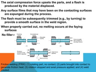
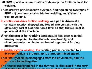
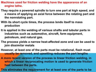
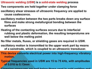
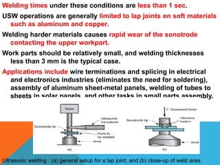
(1) Friction welding and ultrasonic welding are solid-state welding processes that do not involve melting. Friction welding uses rotation or linear motion to generate heat through friction and create a weld. Ultrasonic welding uses high-frequency vibrations to break down surface films and form bonds.
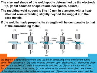
(2) Resistance welding is a fusion process that uses electrical current to generate heat and melt the faying surfaces. Resistance spot welding is widely used in automotive and appliance manufacturing to join sheet metal parts with thousands of spot welds.
(3) Proper parameters of current, time, and pressure are needed to create strong welds without defects in both solid-state and fusion welding processes. Process
2. SOLID STATE-WELDING PROCESSES
The solid-state welding group includes the oldest joining process
as well as some of the most modern.
Each process in this group has its own unique way of creating the
bond at the faying surfaces
Friction Welding is a widely used commercial process, amenable
to automated production methods.
The process was developed in the (former) Soviet Union and
introduced into the United States around 1960.
Friction welding (FRW) is a solid state welding process in which
coalescence is achieved by frictional heat combined with
pressure
The friction is induced by mechanical rubbing between the two
surfaces, usually by rotation of one part relative to the other, to
raise the temperature at the joint interface to the hot working
range for the metals involved.
Then the parts are driven toward each other with sufficient force to
3. The axial compression force upsets the parts, and a flash is
produced by the material displaced.
Any surface films that may have been on the contacting surfaces
are expunged during the process.
The flash must be subsequently trimmed (e.g., by turning) to
provide a smooth surface in the weld region.
When properly carried out, no melting occurs at the faying
surfaces
No filler metal, flux, or shielding gases are normally used.
Friction welding (FRW): (1) rotating part, no contact; (2) parts brought into contact to
generate friction heat; (3) rotation stopped and axial pressure applied; and (4) weld
created.
4. all FRW operations use rotation to develop the frictional heat for
welding.
There are two principal drive systems, distinguishing two types of
FRW: (1) continuous drive friction welding, and (2) inertia
friction welding.
In continuous-drive friction welding, one part is driven at a
constant rotational speed and forced into contact with the
stationary part at a certain force level so that friction heat is
generated at the interface.
When the proper hot working temperature has been reached,
braking is applied to stop the rotation abruptly, and
simultaneously the pieces are forced together at forging
pressures.
In inertia friction welding, the rotating part is connected to a
flywheel, which is brought up to a predetermined speed.
Then the flywheel is disengaged from the drive motor, and the
parts are forced together.
The kinetic energy stored in the flywheel is dissipated in the form
5. Machines used for friction welding have the appearance of an
engine lathe.
They require a powered spindle to turn one part at high speed, and
a means of applying an axial force between the rotating part and
the nonrotating part.
With its short cycle times, the process lends itself to mass
production
It is applied in the welding of various shafts and tubular parts in
industries such as automotive, aircraft, farm equipment,
petroleum, and natural gas.
The process yields a narrow heat-affected zone and can be used to
join dissimilar metals
However, at least one of the parts must be rotational, flash must
usually be removed, and upsetting reduces the part lengths
A more recent version of the process is linear friction welding, in
which a linear reciprocating motion is used to generate friction
heat between the parts.
This eliminates the requirement for at least one of the parts to be
6. Ultrasonic welding (USW) is a solid-state welding process
Two components are held together under clamping force
oscillatory shear stresses of ultrasonic frequency are applied to
cause coalescence.
oscillatory motion between the two parts breaks down any surface
films and make strong metallurgical bonding between the
surfaces
Heating of the contacting surfaces occurs due to interfacial
rubbing and plastic deformation, the resulting temperatures are
well below the melting point
No filler metals, fluxes, or shielding gases are required in USW.
oscillatory motion is transmitted to the upper work part by means
of a sonotrode, which is coupled to an ultrasonic transducer.
This device converts electrical power into high-frequency vibratory
motion.
Typical frequencies used in USW are 15 to 75 kHz, with amplitudes
of 0.018 to 0.13mm
7. Welding times under these conditions are less than 1 sec.
USW operations are generally limited to lap joints on soft materials
such as aluminum and copper.
Welding harder materials causes rapid wear of the sonotrode
contacting the upper workpart.
Work parts should be relatively small, and welding thicknesses
less than 3 mm is the typical case.
Applications include wire terminations and splicing in electrical
and electronics industries (eliminates the need for soldering),
assembly of aluminum sheet-metal panels, welding of tubes to
sheets in solar panels, and other tasks in small parts assembly.
Ultrasonic welding : (a) general setup for a lap joint; and (b) close-up of weld area.
8. Resistance welding (RW) is a group of fusion-welding processes
uses a combination of heat and pressure- heat being generated by
electrical resistance to current flow at the junction to be welded.
resistance spot-welding operation, the most widely used process
in the group.
The components include work parts to be welded (usually sheet
metal parts), two opposing electrodes, a means of applying
pressure to squeeze the parts between the electrodes, and an
AC power supply from which a controlled current can be
applied.
The operation results in a fused zone between the two parts, called
a weld nugget in spot welding.
By comparison to arc welding, resistance welding uses no
shielding gases, flux, or filler metal; and the electrodes that
conduct electrical power to the process are nonconsumable.
RW is classified as fusion welding because the applied heat almost
always causes melting of the faying surfaces. However, there
are exceptions.
9. current used in resistance welding is very high (5000 to 20,000 A,
although voltage is relatively low(below 10V).
The duration t of the current is short in most processes, perhaps
lasting 0.1 to 0.4 s in a typical spot-welding operation.
The reason why such a high current is used in RW is because (1)
the squared term in H = I2Rt amplifies the effect of current, and
(2) the resistance is very low (around 0.0001 V).
Resistance in the welding circuit is the sum of (1) resistance of the
electrodes, (2) resistances of the workparts, (3) contact
resistances between electrodes and workparts, and (4) contact
resistance of the faying surfaces.
Thus, heat is generated in all of these regions of electrical
resistance
The ideal situation is for the faying surfaces to be the largest
resistance in the sum, since this is the desired location of the
weld.
The resistance of the electrodes is minimized by using metals with
very low resistivities, such as copper.
10. the resistance at the faying surfaces depends on surface finish,
cleanliness, contact area, and pressure. No paint, oil, dirt, or
other contaminants should be present to separate the
contacting surfaces.
Resistance spot welding is by far the predominant process in this
group.
It is widely used in mass production of automobiles, appliances,
metal furniture, and other products made of sheet metal.
If one considers that a typical car body has approximately 10,000
individual spot welds
the economic importance of resistance spot welding can be
appreciated.
Resistance spot welding (RSW) is an RW process in which fusion
of the faying surfaces of a lap joint is achieved at one location
by opposing electrodes.
The process is used to join sheet-metal parts of thickness 3 mm or
less, using a series of spot welds, in situations where an airtight
assembly is not required.
11. The size and shape of the weld spot is determined by the electrode
tip, (most common shape round, hexagonal, square)
The resulting weld nugget is 5 to 10 mm in diameter, with a heat-
affected zone extending slightly beyond the nugget into the
base metals.
If the weld is made properly, its strength will be comparable to that
of the surrounding metal.
(a) Steps in a spot-welding cycle, and (b) plot of squeezing force and current during
cycle. The sequence is: (1) parts inserted between open electrodes, (2) electrodes close
and force is applied, (3) weld time-current is switched on, (4) current is turned off but
force is maintained or increased (a reduced current is sometimes applied near the end
of this step for stress relief in the weld region), and (5) electrodes are opened, and the
12. Materials used for RSW electrodes consist of two main groups: (1)
copper-based alloys and (2) refractory metal compositions such
as copper and tungsten combinations.
The second group is noted for superior wear resistance.
As in most manufacturing processes, the tooling in spot welding
gradually wears out as it is used.
electrodes are designed with internal passage ways for water
cooling.
Because of its widespread industrial use, various machines and
methods are available to perform spot-welding operations
The equipment includes rocker-arm and press-type spot-welding
machines, and portable spot-welding guns.
Rocker-arm spot welders, have a stationary lower electrode and a
movable upper electrode that can be raised and lowered for
loading and unloading the work.
The upper electrode is mounted on a rocker arm whose movement
is controlled by a foot pedal operated by the worker
Modern machines can be programmed to control force and current