1. INTRODUCTION TO AUTOMATION SYSTEM
UNIT 1 : INTRODUCTION TO AUTOMATION SYSTEM
General Objectives
1. Understand and learn about automation control systems and types of automation control
systems.
2. Learn about the types of control system pneumatic control systems, hydraulic control systems
and electrical control system.
Specific Objectives;
At the end of this chapter, student should be able to:
1. Define the Automation Control System
2. States the need of Automation Control System in the industry
3. States of the Fixed Automation / Hard-Wire Control System
4. Differentiate between Fixed Automation with Programmable Automation.
5. State the basic concepts of pneumatic control systems, hydraulic control systems and electrical
control systems
6. Classification of pneumatic control systems, hydraulic control systems and electrical control
systems.
7. Distinguish between the pneumatic control system, hydraulic control system and electrical
control systems
1.0 Introduction:
In today’s fast-moving, highly competitive industrial world, a company must be flexible, cost
effective and efficient if it wishes to survive. In the process and manufacturing industries, this
has resulted in a great demand for industrial control systems/ automation in order to
streamline operations in terms of speed, reliablity and product output. Automation plays an
increasingly important role in the world economy and in daily experience.
Automation is the use of control systems and information technologies to reduce the need for
human work in the production of goods and services. In the scope of industrialization,
automation is a step beyond mechanization. Whereas mechanization provided human
operators with machinery to assist them with the muscular requirements of work, automation
greatly decreases the need for human sensory and mental requirements as well.
What is Automation Control System?
Automation Control System - system that is able to control a process with minimal human
assistance or without manual and have the ability to initiate , adjust, action show or measures
the variables in the process and stop the process in order to obtain the desired output.
SARIATI Page 1
2. INTRODUCTION TO AUTOMATION SYSTEM
The main objective of Automation Control System used in the industry are:
1. to increase productivity
2. to improve quality of the product
3. Control production cost
1.1.1 Types Of Automation In The Industry
1.1.1 Classification of automation
a) Permanent/Fixed Automation
- This control system is designed to perform a specific task
- Functions of control circuit is fixed and permanent.
- It will be complicated if we want to do other task apart from the existing task
b) Programmable /Flexible Automation
- Programmable automation or felxible automation is a complex control system that
can perform several tasks
- Functions of control circuit programmed by the user and can be modified.
- When the task to be performed by machines changed, changes only need to be done
by making modifications to the machine control program.
1.1.2 Comparison Between Fixed And Flexible Automation System
FIXED FLEXIBLE
AUTOMATION AUTOMATION
Purpose Specific Variety
Ease of making changes / upgrade
Difficult Easy
Maintenance Hard Easy
Depends on
Capability manufacturing and Very high
design
Speed Slow Fast
Suitable for small Suitable for
Economy efficiency
system all types of systems
SARIATI Page 2
3. INTRODUCTION TO AUTOMATION SYSTEM
Example :
Fixed Automation
S1 S2 lamp
Vs
bB
Programmed Automation:
PROGRAMM
S1 S2
0000 0000 1000
0 1 0
LD 00000
AND 00001
OUT 10000
END (01)
PLC
I O
N U
P T
U P
T U
T
LAMP
S1
S2
COM
COM
Vs
Vs
SARIATI Page 3
4. INTRODUCTION TO AUTOMATION SYSTEM
1.1.3 There Are Three (3) Types Of The Control System Based On Supply :
a) Pneumatic Control Systems
b) Hydraulic Control System
c) Electrical Control System
a) Pneumatic Control System
Pneumatic control system is a system that uses compressed air to produce power /
energy to perform any task
Pneumatic systems found in many industrial systems such as food industry,
petrochemical and industrial involves robotics.
Pneumatic systems requires:
i. Compressed air supply
ii. Control valve
iii. Connecting tube
iv. Transducer
Pneumatic control system can be controlled manually and automatically.
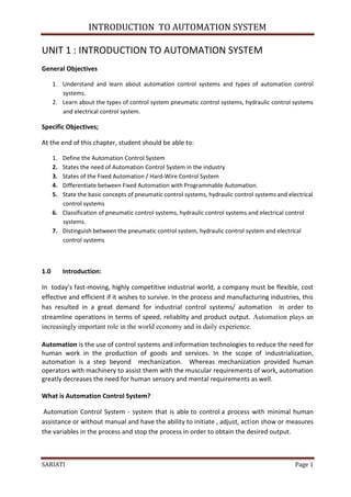
Basic Block Diagram of Pneumatic Control System using manual/PLC
SARIATI Page 4
5. INTRODUCTION TO AUTOMATION SYSTEM
b) Hydraulic Control System
Hydraulic control system is a system that uses fluid to generate power/energy.
The hydraulic system used in the automobile industry such as power systems, braking systems,
cranes, car jack, satellite and others.
The fluid used is oil.
The hydraulic system requires:
a) Hydraulic fluid supply
b) Control Valve
c) Cylinder
Hydraulic control system can be controlled manually and automatically
Basic block diagram of an automatic hydraulic control system by Manual /PLC
c) Electrical Control System
A control system that uses an electric current; either direct current (DC) or current
shuttle (AC) as a source of supply.
Electrical Control Systems Generally requires:
a) Electricity (DC) or (AC)
b) Input elements (switches, sensors, transducer, valves, electronic components,
etc.)
c) Output elements (motor, lights, etc.)
d) Extension cable
SARIATI Page 5
6. INTRODUCTION TO AUTOMATION SYSTEM
Switch
Lamp
Vs
Basic block diagram of a manual electric control system
Switch
Lamp
u
PLC
Vs
Vs
Basic block diagrams of electrical control system using PLC
COMPARISON BETWEEN PNEUMATIC CONTROL SYSTEMS ,HYDRAULIC
CONTROL SYSTEM AND ELECTRIC CONTROL SYSTEM
i. PNEUMATIC CONTROL SYSTEM
a) Easy installation
b) Simple design
c) Use compressed air as a supply source to perform task.
ii. HYDRAULIC CONTROL SYSTEM
a) Complex to assemble
b) Use fluid like oil as a supply source to perform task.
c) Potential leakage will lead to pollution.
iii. ELECTRIC CONTROL SYSTEM
a) Simple system
b) Use electricity as a supply source to perform task.
c) Widely use either for home user or in industrial.
SARIATI Page 6
7. INTRODUCTION TO AUTOMATION SYSTEM
1.1.4 Advantages And Disadvantages Of Automation Control In Industry
The main advantages of automation are:
Replacing human operators in tasks that involve hard physical work.
Replacing humans in tasks done in dangerous environments (i.e. fire, space, volcanoes,
nuclear facilities, underwater, etc.)
Performing tasks that are beyond human capabilities of size, weight, speed, endurance,
etc.
Economy improvement: Automation may improve in economy of enterprises, society or
most of humanity. For example, when an enterprise invests in automation, technology
recovers its investment; or when a state or country increases its income due to
automation like Germany or Japan in the 20th Century.
Reduces operation time and work handling time significantly.
The main disadvantages of automation are:
Unemployment rate increases due to machines replacing humans and putting those
humans out of their jobs.
Technical Limitation: Current technology is unable to automate all the desired tasks.
Security Threats/Vulnerability: An automated system may have limited level of
intelligence, hence it is most likely susceptible to commit error.
Unpredictable development costs: The research and development cost of automating a
process may exceed the cost saved by the automation itself.
High initial cost: The automation of a new product or plant requires a huge initial
investment in comparison with the unit cost of the product, although the cost of
automation is spread in many product batches of things
TUTORIAL QUESTION:
• Give definition of Automation Control System? [3m]
• Make a comparison between Fixed Automation and Flexible Automation Control
System.[12m]
• State three (3) types of control system which based on supply source and states the
differences between them.[12m]
• Sketch an automatic control system diagram for:
a) Hydraulic Control System
b) Electric Control System
c) Pneumatic Control System
SARIATI Page 7
8. INTRODUCTION TO AUTOMATION SYSTEM
1.2Explanation Of Relays And Contactors
The representation of relays and contactors in the electrical circuit diagram is identical, as
their operating principle.
i. Relays are used to switch relatively small output and current.
ii. Contactor to switch relatively large output and currents.
1.2.1 Relays
a) Definition Relay
A relay is an electrically operated switch/electromagnetically actuated switch. Current
flowing through the coil of the relay creates a magnetic field which attracts a lever and
changes the switch contacts. The coil current can be ON or OFF so relays have two switch
positions and most have double throw (changeover) switch contacts .
b) Types of Relays
Relays are usuallly SPDT (Single Pole Double Throw) or DPDT (Double Pole Double
Throw) but they can have many more sets of switch contacts.
Poles : the number of sets of contacts
Throw : The number of positions or combinations (open or close) the contacts have.
Several types of relays shown in the diagram below:
Circuit symbol for a relay
SARIATI Page 8
9. INTRODUCTION TO AUTOMATION SYSTEM
The relay's switch connections are usually labelled COM, NC and NO:
COM = Common, always connect to this, it is the moving part of the switch.
NC = Normally Closed, COM is connected to this when the relay coil is off.
NO = Normally Open, COM is connected to this when the relay coil is on.
Connect to COM and NO if you want the switched circuit to be on when the relay coil
is on.
Connect to COM and NC if you want the switched circuit to be on when the relay coil
is off.
c) Relay Building Diagram
Relays
The actual relay building diagram
A simple electromagnetic relay consists of a coil of wire wrapped around a soft iron
core , an iron yoke which provides a low reluctance path for magnetic flux, a movable iron
armature, and one or more sets of contacts. The armature is hinged to the yoke and
mechanically linked to one or more sets of moving contacts. It is held in place by a spring so
that when the relay is de-energized there is an air gap in the magnetic circuit.
When an electric current is passed through the coil it generates a magnetic field that
activates the armature, and the consequent movement of the movable contact(s) either
makes or breaks (depending upon construction) a connection with a fixed contact.
If the set of contacts was closed when the relay was de-energized, then the movement
opens the contacts and breaks the connection, and vice versa if the contacts were open.
When the current to the coil is switched off, the armature is returned by a force,
approximately half as strong as the magnetic force, to its relaxed position. Usually this force is
provided by a spring, but gravity is also used commonly in industrial motor starters. Most
relays are manufactured to operate quickly. In a low-voltage application this reduces noise; in
a high voltage or current application it reduces arcing.
SARIATI Page 9
10. INTRODUCTION TO AUTOMATION SYSTEM
Relay Building Diagram
1 4
3
2
How Relays Work
1. When switch is ON/press, the current will flow through it
2. It will energize the electromagnet
3. Then the coil (electromagnet) will attract the lever
4. After the lever touch each other, the electricity will flow to the load
Relay can be used for various regulating, control and monitoring functions:
i. As interfaces between control circuits and load circuits
ii. For signal multiplication
iii. For separation of direct current and alternating current circuits
iv. For delaying, generating and converting signals and
v. For linking information.
SARIATI Page 10
11. INTRODUCTION TO AUTOMATION SYSTEM
d) Example Of Relay Use In The Traffic Light System
Operating Principle:
• This circuit can be used to control traffic in public places, or to demonstrate traffic
rules in traffic-parks.
• IC2, which is heart of the circuit, is a decade counter. In this counter for every pulse
fed to pin-14, potential keeps shifting from D1 to D9 in cyclic order.
• IC1 is used as a pulse generator and generates pulses in regular configurable
intervals. These intervals can be changed by varying VR1.
• The circuit is designed in such a way that out of nine pulses, relay RL1 remains
triggered for 4 pulses, relay RL2 for 1 pulse and relay RL3 for remaining 4 pulses.
Since D1-D4 provide current to T1, T1 is on whenever there is potential on any diode
D1 to D4, which keeps relay RL1 triggered. Similarly other diodes are responsible for
RL2 and RL3 triggering.
• Red, Yellow and Green lamps can be connected to the relays RL1, RL2 and RL3
respectively to complete your mini traffic light controller.
SARIATI Page 11
12. INTRODUCTION TO AUTOMATION SYSTEM
1.2.2 Contactors
d) Definition Contactor
A relay that can handle the high power required (higher current rating) to directly
control an electric motor or other loads is called a contactor.
A contactor is an electrically controlled switch used for switching a power circuit, similar
to a relay except with higher current ratings.
Contactors are used to control electric motors, lighting, heating, capacitor banks, and
other electrical loads.
b) Basic Component Of Contactor:
A contactor has three components. The contacts are the current carrying part of the
contactor. This includes power contacts, auxiliary contacts, and contact springs. The
electromagnet provides the driving force to close the contacts. The enclosure is a frame
housing the contact and the electromagnet.
Contactor
Contactor building diagram
A basic contactor will have a coil input (which may be driven by either an AC or DC
supply depending on the contactor design). The coil may be energized at the same voltage as
the motor, or may be separately controlled with a lower coil voltage better suited to control
by programmable controllers and lower-voltage pilot devices.
c) Operating Principle
Unlike general-purpose relays, contactors are designed to be directly connected to
high-current load devices. Relays tend to be of lower capacity and are usually designed for
both normally closed and normally open applications. Devices switching more than 15
amperes or in circuits rated more than a few kilowatts are usually called contactors. Apart
from optional auxiliary low current contacts, contactors are almost exclusively fitted with
SARIATI Page 12
13. INTRODUCTION TO AUTOMATION SYSTEM
normally open contacts. Unlike relays, contactors are designed with features to control and
suppress the arc produced when interrupting heavy motor currents.
When current passes through the electromagnet, a magnetic field is produced, which
attracts the moving core of the contactor. The electromagnet coil draws more current initially,
until its inductance increases when the metal core enters the coil. The moving contact is
propelled by the moving core; the force developed by the electromagnet holds the moving
and fixed contacts together. When the contactor coil is de-energized, gravity or a spring
returns the electromagnet core to its initial position and opens the contacts.
i. Main Contact.
Main contact of the contactor are normaly open contact and usually use to connect power
load to the main supply.
ii. Auxiliary Contacts
Auxiliary contacts are secondary switching devices which work in conjunction with primary
switching equipment such as circuit breakers, relays, and contactors. These contacts are
physically linked to the main switching mechanism and activate at the same time it does.
Auxiliary contacts are commonly used as interlocks or retainers on the primary device's
control circuit and often used to give indication of its state of operation such as trip function
indication, electrical interlocks, and start circuit retainers.. Many contactors and circuit
breakers feature sets of auxiliary contacts as integral parts or they may be modular snap on
units which can be added or removed as required. Auxiliary contacts are available with either
normally open or normally closed contact points or a combination of both.
d) Examples Application Of Contactor In Motor Control Sytem.
1. DOL Motor Starter
2. A STAR DELTA Motor Starter
SARIATI Page 13
14. INTRODUCTION TO AUTOMATION SYSTEM
1.2.3 Difference Between Relay And Contactors
The Difference :
1. Since a contactor is required for a higher load, a relay is always cheaper than a
contactor.
2. A relay is normally used in appliances below 5KW, while a contactor is preferred
when the appliance is heavier.
3. A relay is used only in control circuit while a contactor can be used in both control
and power circuits.
4. In general contactors are little slower than relays
5. Contactor is so designed that it can be repaired while it is not normally done in the
case of relays.
NOTES:
It should be noted that when installing contactors or relays that you always check the coil
ratings. They often have not got a default rating of 230volts, and only go bang once if they are
connected to the wrong voltage!
SARIATI Page 14
15. Differences between Pneumatic,
Hydraulic and Electrical control
system
Pneumatic Hydraulic Electric
1 Using Compress air as Using oil as supply source Using electricity as a
supply source supply source
2 Easy installation Complicated Installation Simple system
3 Simple design If leak will cause dirty Widespread use
17. WHAT IS RELAY…
• A relay is an electrically operated switch.
Current flowing through the coil of the relay
creates a magnetic field which attracts a lever
and changes the switch contacts. The coil
current can be on or off so relays have two
switch positions and most have double throw
(changeover) switch contacts as shown in the
diagram.
Symbol of relay
18. Several design of relay are in used today, 3-
pin,4-pin,5-pin,6-pin, single switch or dual
switches
20. How relay works..
1. When switch is ON/press, the current will
flow through the coil.
2. It will energize the electromagnet
3. Then the coil (electromagnet) will attract the
lever
4. After the lever touch each other, the
electricity will flow to the load
21. Types of Relays
• Relays are usuallly SPDT (Single Pole Double
Throw) or DPDT (Double Pole Double Throw)
but they can have many more sets of switch
contacts.
• Poles : the number of sets of contacts
• Throw : The number of positions or
combinations (open or close) the contacts
have.
22. Types of relay..
This is a Single Pole Double
SPDT-Single Pole Double Throw Throw relay. Current will
flow between the movable
contact and one fixed
contact (NC) when the coil
is de-energized.
When the relay coil is
energized the current will
flow between the movable
contact and the alternate
fixed contact (NO).
23. DPDT – Double Pole Double Throw
This relay is a Double
Pole Double Throw
relay. It operates like
the SPDT relay but
has twice as many
contacts. There are
two completely
isolated sets of
contacts.
25. Relay application
• Relay can be used for various regulating,
control and monitoring functions:
• As interfaces between control circuits and load circuits
• For signal multiplication
• For separation of direct current and alternating current
circuits
• For delaying, generating and converting signals and
• For linking information.
28. Operating Principle:
• This circuit can be used to control traffic in public places, or to
demonstrate traffic rules in traffic-parks.
• IC2, which is heart of the circuit, is a decade counter. In this counter
for every pulse fed to pin-14, potential keeps shifting from D1 to D9 in
cyclic order.
• IC1 is used as a pulse generator and generates pulses in regular
configurable intervals. These intervals can be changed by varying VR1.
• The circuit is designed in such a way that out of nine pulses, relay RL1
remains triggered for 4 pulses, relay RL2 for 1 pulse and relay RL3 for
remaining 4 pulses. Since D1-D4 provide current to T1, T1 is on
whenever there is potential on any diode D1 to D4, which keeps relay
RL1 triggered. Similarly other diodes are responsible for RL2 and RL3
triggering.
• Red, Yellow and Green lamps can be connected to the relays RL1, RL2
and RL3 respectively to complete your mini traffic light controller.
29. WHAT IS CONTACTOR
A contactor is an electrically
controlled switch used for
switching a power circuit,
similar to a relay except with
higher current ratings.
A contactor is controlled by a
circuit which has a much lower
power level than the switched
circuit.
30. How the contactor works
• When current passes through the electromagnet, a magnetic
field is produced, which attracts the moving core of the
contactor.
• The electromagnet coil draws more current initially, until its
inductance increases when the metal core enters the coil. The
moving contact is propelled by the moving core; the force
developed by the electromagnet holds the moving and fixed
contacts together.
• When the contactor coil is de-energized, gravity or a spring
returns the electromagnet core to its initial position and
opens the contacts.
33. Relay vs Contactor
RELAY CONTACTOR
Use for lower load, below 5KW Use for high load
Light duty switch Heavy duty switch
controlled device that opens and for repeatedly establishing and
closes electrical contacts to effect the interrupting an electrical power
operation of other devices in the circuit
same or another circuit.
relay is used in control circuit only contactor is used in both control
and power circuit.
Cheaper Expensive
Not economically to repair Designed that it can be repaired
34. INTRODUCTION TO PLC
CHAPTER 2: INTRODUCTION TO PLC
Objectives:
At the end of this lecture the students should be able to:
1. Describe a PLC and its functions
2. Explain the history of PLC development
3. Identify the mains part of PLC and describe the functions.
4. List the types and advantages of PLC
2.0 INTRODUCTION
In this chapter , we will discussed about PLC in detail:
2.1 Definition of PLC
2.2 Define PLC Terminologies
2.3 Background PLC
2.3 The function of PLC and Types of Construction
2.4 Advantages of PLCs
2.1 Definition of PLC
Definition according to NEMA standard ICS3-1978
A digitally operating electronic apparatus which uses a programming memory for the
internal storage of instructions for implementing specific functions such as logic,
sequencing, timing, counting and arithmetic to control through digital or analog modules,
various types of machines or process.
OR
A device that is pre-programmed to accept relay ladder logic instructions and perform these
instructions to control the equipment operation.
SARIATI Page 1
35. INTRODUCTION TO PLC
2.2 PLC Terminologies
sensors: switches, flow, level, pressure, temp. transmitters, etc.
output devices/actuators: motors, valves, solenoids, lamps, or audible devices
SARIATI Page 2
36. INTRODUCTION TO PLC
CPU - Central Processing Unit.
The CPU is a microprocessor that co-ordinates the activities of the PLC system. Its executes
the program, processes I/O signals & communicates with external devices
Ladder Diagram -
Ladder diagrams are specialized schematics commonly used to document industrial control
logic systems. They are called "ladder" diagrams because they resemble a ladder, with two
vertical rails (supply power) and as many "rungs" (horizontal lines) as there are control
circuits to represent built from relays, is being simulated
2.2 Background of PLC
Among the factors that create the initial design and development of control systems
that can be controlled are as follows:
i. Requirements of a low cost
ii. Intelligent system
iii. The Controller that is easy to control
The first PLC was designed by a team of engineers at the company General
Motors (GM), the United States in 1968 when the company is looking for other methods
to replace the complex system of relays. They also set the specifications of the new
control system must meet the following requirements:
i. Easily programmed
ii. There is no need for rewiring if there are changes on the program
iii. Smaller, cheaper and higher reliability.
iv. Simple building construction and the maintenance cost is cheap.
v. Cost competitive
SARIATI Page 3
37. INTRODUCTION TO PLC
2.3 FUNCTIONS AND TYPE OF CONSTRUCTION
2.3.1 Function of PLC
PLC can perform various functions, such as follows :
Type of control Function
Sequence Control 1. Successor Control Relay - conventional logic
2. Timer/counter
3. Substitute PCB Control card
4. Machine and Process Controller for Automatic, Semi-
auto and manual
Advanced Control 1. Solve Mathematics of Operations
(+, , , x)
2. Managing Information
3. Analog control (temperature, pressure, etc..)
4. Servo Motor Control
5. Stepper motor control
6. control P.I.D (Propotional - Integral - derivation)
Supervision control 1. Process Display and Alarm
2. Diagnosis and Display Fault
3. Interface with Computer
(RS 232C / RS 422)
4. Interface Printer / ASCII
5. Factory Automation Network
6. Local Area Network (LAN)
7. Widespread Area Network (WAN)
8. Factory Automation (FA),Flexible Manufacturing
System (FMS), Computer Integrated Manufacturing
(CIM) etc..
2.3.2 Type of PLC Construction
Figure 2.3.2 shows the types of PLC construction in the market today.
Types of PLC construction.
SARIATI Page 4
38. INTRODUCTION TO PLC
2.4. Advantages of PLC are as follows:
The implementation of a short control projects.
Program can be change easily.
Accurate calculation of the cost project.
Requires a short training time.
Flexible control system design using the software.
A wide range of control applications.
Easy maintenance.
High reliability
A standard Hardware controller
Resistance to the problems of the environment (temperature,
moisture, voltage instability and noise) is good.
SARIATI Page 5
39. PLC HARDWARE DESIGN
CHAPTER 3 – PLC HARDWARE DESIGN
Objectives:
After completed this chapter, the student will know the major components of a PLC and the
functions of these components.
Introduction:
The PLC, being a microprocessor based device, has a similar internal structure to many
embedded controllers and computers. A PLC consist of the following components:
i. CPU,
ii. Memory
iii. Input modules
iv. Output modules
v. Power supply.
These components are integral to the PLC controller. Additionally the PLC has a connection
for the Programming and Monitoring Unit, Printer and Program Recorder.
3.1 Hardware Design of PLC
DATA BUS
Micro- RAM
ROM Input Output
processor
Operation Programming Unit/ Unit/
system Data Module Module
( CPU ) Output
Unit
ADDRESS BUS
CONTROLLED BUS
a) Design Of A Basic Microcomputer
SARIATI Page 1
40. PLC HARDWARE DESIGN
b) PLC Hardware Block Diagram
3.1.1 Explanation of the PLC Block Diagram
The programming terminal in the diagram (b) is not part of the PLC, but it is essential to
have a terminal for programming or monitoring a PLC. In the diagram , the arrows between
blocks indicate the information and power flowing directions.
a) Central Processing Unit - CPU
This unit is the most important unit in the building of a PLC , which is the “brain” of a PLC.
In this unit lies a chip of microprocessor - intergrated circuit chips which controls the overall
operation of the PLC control system. Microprocessors contain arithmatic unit, control unit
and a number of memory units, known as registrars.
The main function of the microprocessor is to analyze data coming from field sensors
through input modules, make decisions based on the user’s defined control program and
return signal back through output modules to the field output devices.
In detail, the CPU of a PLC does the following operation:
Updating inputs and outputs. This function allows a OLC to read the status of its
input terminals and energize or deenergize its output terminals.
Performing logic and arithmetic operations. A CPU conducts all the mathematic and
logic operations involved in a PLC.
Communicating with memory. The PLC programs and data are stored in memory.
When a PLC operating, its CPU may read or change the contents of memory
locations.
Scanning application programs. An application program , which is called a ladder
logic program , is a set of instructions written by a PLC programmer. The scanning
function allows the PLC to execute the application program as specified by the
SARIATI Page 2
programmer.
41. PLC HARDWARE DESIGN
Communicating with a programming terminal. The CPU transfers program and data
between itself and the programming terminal.
b) Memory Unit
Memory is the component that stores information, programs and data in a PLC. The
process of putting new information into a memory location is called writing. The
process of retrieving information from a memory location is called reading.
Above figure shows the memory unit in the internal design of PLCs. This unit contains
two (2) types of memory:
i. RAM (Random Access Memory)
RAM is the memory type of read / write and easy to program and repaired.
All users program are stored in this memory. Read indicates that the information
stored in the memory can be retrieved or read, while write indicates that the
user can program or write information into the memory. The data in the RAM
would normally be lost if the power source is removed. This problem is solved by
backing up the RAM with the battery
ii. ROM (Read Only Memory)
ROM is read-only memory types. Read Only indicates that the information stored
in memory can be read only and cannot be changed. Information in ROM is
placed there by the manufacturer for the internal use and operation of the PLC.
The system program is stored in this memory. This program will not be lost when
the power is disconnected. Special equipment is used to delete the program
from this memory
The memory capacities of PLCs vary.
c) Display and Indicators Unit
Display and the indicator unit refers to the internal relay PLC status display. This can be seen
in the Console programming if the user using the mnemonic code and programming
computer screen if the user using software programming methods.
d) Input And Output Unit /Module
SARIATI Page 3
42. PLC HARDWARE DESIGN
Referring to above figure, the input and output units are the units available in the internal
design of PLCs.
The Input/Output units are the interfaces between the internal PLC systems and the
external processes/ field devices to be monitored and controlled. Input Unit is the unit
which input devices (switches, sensors) are connected to it. While the output unit is a unit
which output devices (Lights, motors) are connected to it.
The main purpose of the I/O interface is to condition the various signals received from or
sent to the external input and output devices. Input modules converts signals from
discrete or analog input devices to logic levels acceptable to PLC’s processor. Output
modules converts signal from the processor to levels capable of driving the connected
discrete or analog output devices.
Since the PLC is a logic based device with a typical operating voltage of 5 volts and the
external processes usually demand higher powers and currents, the I/O modules are
optically or otherwise isolated. The typical I/O operating voltages are 5V - 240 V dc (or ac)
and currents from 0.1A up to several amperes. The I/O modules are designed in this way to
minimize or eliminate the need for any intermediate circuitry between the PLC and the
process to be controlled.
Small PLC units would have around 40 I/O connections with larger ones having more than
128 with either local or remote connections and extensive upgrade capabilities.
3.2 Function And Operation Of The Following Hardware Units
3.2.1 Housing Unit
This unit provides protection to the circuits and components - the internal components of a
PLC.
3.2.2 Programming Unit
Programming units are essential components of the PLC systems. Since they are used only in
the development/testing stage of a PLC program, they are not permanently attached to the
PLC. The program in a ladder diagram or other form can be designed and usually tested
before downloading to the PLC. The Programming unit can be a dedicated device or a
personal computer. It allows the graphical display of the program (ladder diagram). The
unit, once connected to the PLC can download the program and allows for the real time
monitoring of its operation to assist debugging. Once the program is found to operate as
required the Programming Unit is disconnected from the PLC which continues the operation
SARIATI Page 4
43. PLC HARDWARE DESIGN
3.2.3 Program Loader Unit
Is used to enter the desired program into the memory of the processor. Program is entered
using relay ladder logic (most popular programming language used by all major
manufacturers of PLCs). Program loader can be a computer or a console (handheld type).
All leading brands of PLCs have software available so that a PC can be used as the
programming device.
3.2.4 Secondary Storage Unit
This unit is related to the Central Processing Unit where all the programs and information
stored
3.2.5 VDU (Video Display Unit)
Information processing unit operations and the system status will be displayed by the PLC
3.2.6 Power Supply Unit
This unit provides power to the Central Processing Unit, Input Unit and Output Unit. PLCs
are powered by standard commercial Ac power lines. However , many PLC components such
as CPU and memory, utilize 5 volts or another level of DC power. The PLC power supply
converts Ac power into Dc power to support those components of the PLC.
3.2.7 Printers
This unit is used to print the program a system controlled by a PLC control either graphics or
text.
Tutorial :
ANSWER ALL THESE QUESTIONS
1.1 State THREE (3) units available in the microprocessor.
1.2 Explain the difference between RAM and ROM memory.
1.3 What do you understand about the Input Unit and Output Unit
1.4 Explain the functions of the printer unit.
SARIATI Page 5
44. PLC HARDWARE DESIGN
QUESTION
a. State TWO (2) information contained in the definition of PLC by NEMA.
b. List Five (5) tasks can be done by the PLC in the control of advanced types.
c. List Five (5) the reason why the factory used the PLC as a controller process automation
control system.
d. Briefly explain any three (3) the units of the PLC hardware
SARIATI Page 6