SlideShare a Scribd company logo
1 of 29
Download to read offline
Consortium for Electric Reliability Technology Solutions
White Paper on
Integration of Distributed Energy Resources
The CERTS MicroGrid Concept
Prepared for
Transmission Reliability Program
Office of Power Technologies
Assistant Secretary for Energy Efficiency and Renewable Energy
U.S. Department of Energy
Energy Systems Integration Program
Public Interest Energy Research
California Energy Commission
Prepared by
Robert Lasseter, Abbas Akhil, Chris Marnay, John Stephens,
Jeff Dagle, Ross Guttromson, A. Sakis Meliopoulous, Robert Yinger, and Joe Eto
April, 2002
The work described in this report was coordinated by the Consortium for Electric Reliability Technology Solutions,
and funded by the Assistant Secretary of Energy Efficiency and Renewable Energy, Office of Power Technologies
of the U.S. Department of Energy under Contract No. DE-AC03-76SF00098 and by the California Energy
Commission, Public Interest Energy Research Program, under Work for Others Contract No. BG 99-39.
2
Table of Contents
1. Introduction ......................................................................................................... 1
2. Background......................................................................................................... 2
2.1 Technologies .........................................................................................................................2
2.2 Combined Heat and Power (CHP) ........................................................................................4
2.3 Interconnection Issues...........................................................................................................5
3. MicroGrid Structure.......................................................................................... 6
3.1 Microsource Controller .........................................................................................................7
3.2 Energy Manager....................................................................................................................8
3.3 Protection ..............................................................................................................................8
3.4 Large Systems-Interconnected MicroGrids – Power Parks ..................................................8
4. MicroGrid Presentation to the Grid.................................................................. 9
4.1 Load as a Resource................................................................................................................9
4.2 Dynamic Interactions ..........................................................................................................10
5. Control Methods for MicroGrids ................................................................... 11
5.1 Microsource Control Functions...........................................................................................11
5.2 Example System..................................................................................................................14
6. Protective Relaying and MicroGrids.............................................................. 16
6.1 Events Occurring During Normal Operation ......................................................................17
6.2 Events on the Isolated MicroGrid .......................................................................................19
7. MicroGrid Economics...................................................................................... 20
7.1 MicroGrids and Traditional Power System Economics.....................................................22
7.2 Newer Economic Issues in MicroGrids .............................................................................25
7.3 Economic Issues Between MicroGrids and the Bulk Power Systems ...............................25
8. Conclusion......................................................................................................... 26
1
1. Introduction
Evolutionary changes in the regulatory and operational climate of traditional electric utilities and
the emergence of smaller generating systems such as microturbines have opened new
opportunities for on-site power generation by electricity users. In this context, distributed energy
resources (DER) - small power generators typically located at users’ sites where the energy (both
electric and thermal) they generate is used - have emerged as a promising option to meet growing
customer needs for electric power with an emphasis on reliability and power quality. The
portfolio of DER includes generators, energy storage, load control, and, for certain classes of
systems, advanced power electronic interfaces between the generators and the bulk power
provider. This white paper proposes that the significant potential of smaller DER to meet
customers’ and utilities’ needs can be best captured by organizing these resources into
MicroGrids1
.
The Consortium for Electric Reliability Technology Solutions (CERTS)
MicroGrid concept assumes an aggregation of loads and microsources
operating as a single system providing both power and heat. The majority of
the microsources must be power electronic based to provide the required
flexibility to insure operation as a single aggregated system. This control
flexibility allows the CERTS MicroGrid to present itself to the bulk power
system as a single controlled unit that meets local needs for reliability and
security.
The CERTS MicroGrid represents an entirely new approach to integrating DER. Traditional
approaches for integrating DER focus on the impacts on grid performance of one, two, or a
relatively small number of microsources. An example of the traditional approach to DER is
found in the Institute of Electrical and Electronics Engineers (IEEE) Draft Standard P1547 for
Distributed Resources Interconnected with Electric Power Systems. This standard focuses on
ensuring that interconnected generators will shut down automatically if problems arise on the
grid. By contrast, the CERTS MicroGrid would be designed to seamlessly separate or island
from the grid and, reconnecting to the grid once they are resolved.
A critical feature of the CERTS MicroGrid derives from its presentation to the surrounding
distribution grid as a single self-controlled entity; that is, it appears to the grid as
indistinguishable from other currently legitimate customer sites. Maintaining this profile relies
on the flexibility of advanced power electronics that control the interface between microsources
and their surrounding AC system. In other words, the CERTS MicroGrid concept eliminates
dominant existing concerns and the consequent approaches for integrating DER. Current
1
The key feature of candidate DER generating technologies for use by the CERTS MicroGrid concept is their
interconnection through inverter-like power electronics, and not any particular rated kW power capacity. For
pragmatic reasons of availability and controllability this CERTS effort is initially focused on microturbines and
assumes their size is less than 500 kW. However, fuel cells and other emerging technologies that might ultimately
be used in MicroGrids could be larger. The role that MicroGrids can play as elements of larger power parks whose
total installed capacity is measures in the 10’s of MW is also illustrated.
2
attention tends to focus on assessing how many DER can be tolerated before their collective
electrical impact begins to create problems, such as excessive current flows following faults and
voltage fluctuations. The MicroGrid architecture insures that its electrical impact on its bulk
power provider at least qualifies it as a good citizen; that is, it complies with grid rules and does
no harm beyond what would be acceptable from an existing customer. Given attractive
remuneration, the MicroGrid could provide interruptible load. Although technical barriers
discourage it, the MicroGrid could serve as a small source of power or ancillary services, thereby
potentially making it a model citizen. The benefits it could offer to the distribution system are
congestion relief, postponement of new generation or delivery capacity, response to load changes
and local voltage support.
From the grid’s perspective, the central advantage of a MicroGrid is that it can be regarded as a
controlled entity within the power system that can be operated as a single aggregated load. In
other words, it can establish binding contractual agreements with the bulk power provider
covering its pattern of usage that are at least as strict as those covering existing customers, and it
potentially it could provide additional services.
Customers benefit from a MicroGrid because it is designed and operated to meet their local
needs for heat and power as well as provide uninterruptible power, enhance local reliability,
reduce feeder losses, and support local voltages/correct voltage sag. The pattern of exchange of
energy services between the MicroGrid and the bulk power provider grid is determined by
prevailing economic conditions.
This white paper explores key technical issues raised by the MicroGrid concept. Background
and contextual information relevant to MicroGrids is presented in Section 2.0, which briefly
describes generation technologies implementable in MicroGrids and the particular role that
combined heat and power could play in MicroGrids. Section 3.0 describes MicroGrid design and
operation in detail. Key technical challenges associated with MicroGrids are delineated in the
next three sections - their presentation to the bulk power provider grid (Section 4.0), controls
required for them to function effectively both in connection to the bulk power provider grid and
in isolation (or islanded) from the grid (Section 5.0), protection and safety issues that must be
addressed (Section 6.0). Section 7.0 discusses some fundamental economic questions that will
ultimately dictate the configuration and operation of the MicroGrid. Section 8.0 summarizes the
issues presented in the paper and highlights areas of needed research. Appendices A-D examine
in detail the background and contextual issues related to MicroGrids: generation technologies,
electrical issues, and environmental and regulatory constraints.
2. Background
2.1 Technologies
As discussed earlier, the key feature that makes the MicroGrid possible is the power electronics,
control, and communications capabilities that permit a MicroGrid to function as a
semiautonomous power system. The power electronics are the critical distinguishing feature of
the MicroGrid, and they are discussed in detail below. This section describes some of the other
technologies whose development will shape MicroGrids. While the more familiar reciprocating
engines will likely remain competitive in many applications for the foreseeable future, they lack
3
power electronics therefore minimizing their role in MicroGrids. Widespread use of fuel cells,
particularly high temperature ones most interesting for combined heat and power (CHP)
applications, remains a few years away. Among the renewable technologies, medium to large
photovoltaic systems, possibly building integrated, are a particularly promising technology,
while other renewables may also play a role. In addition to generating technologies, MicroGrids
also include storage, load control and heat recovery equipment.
Microturbines, currently in the 25-100 kW range, although larger ones are under development,
may ultimately be mass-produced at low cost. These are mechanically simple, single shaft
devices, using high-speed (50,000-100,000 rpm) typically with airfoil bearings. They are
designed to combine the reliability of commercial aircraft auxiliary power units (APU’s) with the
low cost of automotive turbochargers. Despite their mechanical simplicity, microturbines rely on
power electronics to interface with loads. Example products include: Capstone's 30-kW and 60-
kW systems, the former Honeywell 75-kW Parallon machine, and products from European
manufacturers Bowman and Turbec that feature CHP capabilities. Microturbines should also be
acceptably clean running. Their primary fuel is natural gas, although they may also burn propane
or liquid fuels in some applications, which permits clean combustion, notably with low
particulates.
Fuel cells are also well suited for distributed generation applications. They offer high efficiency
and low emissions but are currently expensive. Phosphoric acid cells are commercially available
in the 200-kW range, and high temperature solid-oxide and molten-carbonate cells have been
demonstrated and are particularly promising for MicroGrid application. A major development
effort by automotive companies has focused on the possibility of using on-board reforming of
gasoline or other common fuels to hydrogen, to be used in low temperature proton exchange
membrane (PEM) fuel cells. Fuel cell engine designs are attractive because they promise high
efficiency without the significant polluting emissions associated with internal combustion
engines. Many other major companies are investing in PEM fuel cells for mobile applications,
and the recently announced Bush administration FreedomCAR Initiative should accelerate
development. This will accelerate PEM development relative to other fuel cells, should lower
costs, and will partially compensate for the relatively unattractiveness of low-temperature PEMs
for CHP applications. Higher temperature PEMs are also under development.
Renewable generation could appear in MicroGrids, especially those interconnected through
power electronic devices, such PV systems or some wind turbines. Biofueled microturbines are
also a possibility. Environmentally, fuel cells and most renewable sources are a major
improvement over conventional combustion engines.
Storage technologies, such as batteries, and ultracapacitors are important components of
MicroGrids. Storage on the microsource’s dc bus provides ride-through capabilities during
system changes. Storage systems have become more versatile than they were five years ago.
Twenty eight-cell ultracapacitors can provide up to 12.5 kW for a few seconds.
Heat recovery technologies for use in CHP systems are necessary for MicroGrid viability, as is
explained in the following section. Many of these technologies are relatively developed and
4
familiar, such as low and medium temperature heat exchangers. Others, such as absorption
chillers, are known but not in widespread use.
Environmentally, fuel cells and most renewable sources are a major improvement over
conventional combustion engines. Microturbines should also be acceptably clean running. Their
primary fuel will be natural gas, although they may also burn propane or liquid fuels in some
applications, which permits clean combustion, notably with low particulates. NOx emissions,
which are a precursor to urban smog, are mainly a consequence of combustion. Some traditional
combustion fuels, notably coal, contain nitrogen that is oxidized during the combustion process,
but even burning fuels that contain no nitrogen emits NOx, which forms at high combustion
temperatures from the nitrogen and oxygen in the air. Gas turbines, reciprocating engines, and
reformers all involve high temperatures that result in NOx production. These devices must be
carefully designed to limit NOx formation. Thermal microsources that effectively use waste heat
can also have low overall carbon emissions that compete with those of modern central station
combined-cycle generators. Human exposure to smog also depends on the location of smog
precursor emissions. Since DER is likely to move NOx emissions closer to population centers,
exposure patterns will be affected.
Finally, it should be recognized that many of the MicroGrid technologies will be fueled by
natural gas, at least initially, and expanded use of DER will require added natural gas delivery
infrastructure, some of it preferably at high pressure to serve microturbines.
2.2 Combined Heat and Power (CHP)
One important potential benefit of MicroGrids is an expanded opportunity to utilize the waste
heat from conversion of primary fuel to electricity. Because typically half to three-quarters of
the primary energy consumed in power generation is ultimately released unutilized to the
environment, the potential gains from using this heat productively are significant.
The gains of increased conversion efficiency are threefold. First, fuel costs will be reduced both
because individual fuel purchases will decrease and constrained overall demand will drive down
fuel prices. Second, carbon emissions will be reduced. And, third, the environmental problem of
disposing of large power plant waste heat into the environment will diminish. The emergence
and deployment of technologies to facilitate efficient local use of waste heat is, therefore, key for
MicroGrids to emerge as a significant contributor to the national electricity supply.
Use of waste heat in grid scale CHP systems is more common in many economies than in the
U.S. where it is typically only found in industrial facilities. For example, in Denmark as of 1996,
CHP plants met 48 percent of the domestic electricity demand and 38 percent of the domestic
heat demand. This level of CHP contribution is believed to reduce CO2 emissions by
approximately 7-10 Mt per year, or more than 10 percent of the total CO2 emissions of the
country, relative to estimated emissions if heat and power were produced separately. Most of the
heat capture that enables such impressive results is achieved in medium-sized systems that are at
larger scales than MicroGrids. However, some European countries, notably The Netherlands,
have made significant progress towards developing smaller, i.e. kW scale, CHP applications,
such as greenhouse heating.
5
Unlike electricity, heat, usually in the form of steam or hot water, cannot be easily or
economically transported long distances, so CHP systems typically provide heat for industrial
processes, on-site space heating, local district heating, or for domestic hot water or sterilization.
To make CHP systems viable, a sufficiently large need for heat must exist within a sufficiently
dense area that circulation of steam, hot water, or another appropriate medium is feasible and
economic. Given that space cooling and refrigeration are both significant consumers in the U.S.,
application of absorption cooling and/or desiccant dehumidification could be a highly attractive
feature of MicroGrids. These are key enabling technologies for MicroGrids and DER generally.
MicroGrids can capture two significant potential advantages over existing larger scale CHP
systems:
1. The production of heat can move closer to the point of use. In an extreme example, fuel cells
could be placed on every floor of a hospital to meet each floor’s hot water needs. Because
electricity is more readily transported than heat, generation of heat close to the location of the
heat load will usually make more sense than generation of heat close to the electrical load,
and the MicroGrid permits generators to be placed optimally in relation to heat loads.
2. The scale of heat production for individual units is small and therefore offers greater
flexibility in matching to heat requirements. A MicroGrid could be constructed from the
most economic combination of waste-heat-producing generators and non-waste-heat
producing generators so that the combined generation of electricity and heat is optimized.
Against these advantages, the possible non-coincidence of electricity and heat requirements
will pose a significant handicap in many situations. Further, systems must be flexible for
changing patterns of use, especially because small businesses have short average life spans.
2.3 Interconnection Issues
Local interconnection standards vary considerably from one bulk power provider to the next. A
national standard, ANSI standard P1547 (Draft) Standard for Distributed Resources
Interconnected with Electric Power Systems is being drafted by the IEEE SCC21 working group.
This standard rests on certain assumptions about the contribution of DER to power quality and
system reliability. Although P1547 does not use the term MicroGrid, it allows for
implementation of a group of DER, which it refers to as a Local Electric Power System (LEPS).
The standard applies at the point where a LEPS or MicroGrid connects to the grid and is related
to the aggregate DER rating within the MicroGrid. In other words, the rules applied to a
MicroGrid containing many small DER devices would be the same as for one large DER.
However, the applicability of P1547 is limited to a DER rating of 10 MVA, which is larger than
the ratings expected for MicroGrids.
6
3. MicroGrid Structure
The MicroGrid structure assumes an aggregation of loads and microsources operating as a single
system providing both power and heat. The majority of the microsources must be power
electronic based to provide the required flexibility to insure controlled operation as a single
aggregated system. This control flexibility allows the MicroGrid to present itself to the bulk
power system as a single controlled unit, have plug-and-play simplicity for each microsource,
and meet the customers’ local needs. These needs include increased local reliability and security.
Key issues that are part of the MicroGrid structure include the interface, control and protection
requirements for each microsource as well as MicroGrid voltage control, power flow control,
load sharing during islanding, protection, stability, and over all operation. The ability of the
MicroGrid to operate connected to the grid as well as smooth transition to and from the island
mode is another important function.
Feede r A
Feede r C
Zone-1
PCC
Zone-2
Zone-3 Zone-4
Feede r B
Zone-5
Zone-6
Energy Manage r
Sensitive Loads
Traditional Load s
SD
Powe r &
Voltage
Con troller
Pointof
Common
Coup ling
Breaker Sepa ration
Dev ice
Zone-7
Heat
Load
Figure 3.1 MicroGrid Architecture
Figure 3.1 illustrates the basic MicroGrid architecture. The electrical system is assumed to be
radial with three feeders – A, B, and C – and a collection of loads. The microsources are either
Micro-
Source
7
microturbines or fuel cells interfaced to the system through power electronics. The Point of
Common Coupling (PCC) is on the primary side of the transformer and defines the separation
between the grid and the MicroGrid. At this point the MicroGrid must meet the prevailing
interface requirements, such as defined in draft standard IEEE P1547.
The sources on Feeder A & B allow full exploration of situations where the microsources are
placed away from the common feeder bus to reduce line losses, support voltage and/or use its
waste heat. Multiple microsources on a radial feeder increase the problem of power flow control
and voltage support along the feeder when compared to all sources being placed at the feeder’s
common bus, but this placement is key to the plug-and-play concept. The feeders are usually 480
volts or smaller. Each feeder has several circuit breakers and power and voltage flow controllers.
The power and voltage controller near each microsource provides the control signals to the
source, which regulates feeder power flow and bus voltage at levels prescribed by the Energy
Manager. As downstream loads change, the local microsource’s power is increased or decreased
to hold the total power flow at the dispatched level.
In Figure 3.1 there are two feeders with microsources and one without any generation to
illustrate a wide range of options. During disturbances on the bulk power system Feeders A & B
can island using the separation device (SD) to minimize disturbance to the sensitive loads. Of
course islanding does not make sense if there is not enough local generation to meet the demands
of the sensitive loads. The traditional loads on Feeder C are left to ride through the disturbance.
This eliminates nuisance trips of the traditional load when the MicroGrid islands to protect
critical loads.
The MicroGrid assumes three critical functions that are unique to this architecture.
• Microsource Controller. The Power and Voltage Controller coupled with the microsource
provide fast response to disturbances and load changes without relying on communications.
• Energy Manager. Provides operational control through the dispatch of power and voltage
set points to each Microsource Controller. The time response of this function is measured in
minutes.
• Protection. Protection of a MicroGrid in which the sources are interfaced using power
electronics requires unique solutions to provide the required functionality.
3.1 Microsource Controller
The basic operation of the MicroGrid depends on the Microsource Controller to; regulate power
flow on a feeder as loads on that feeder change their operating points; regulate the voltage at the
interface of each microsource as loads on the system change; and insure that each microsource
rapidly picks up its share of the load when the system islands. In addition to these control
functions the ability of the system to island smoothly and to automatically reconnect to the bulk
power system is another important operational function. Most of this set of key functions does
not exist on currently available microsources.
Another important feature of each Microsource Controller is that it responds in milliseconds and
uses locally measured voltages and currents to control the microsource during all system or grid
8
events. Fast communication among microsources is not necessary for MicroGrid operation; each
inverter is able to respond to load changes in a predetermined manner without data from other
sources or locations. This arrangement enables microsources to “plug and play” – that is,
microsources can be added to the MicroGrid without changes to the control and protection of
units that are already part of the system. The basic inputs to the Microsource Controller are
steady-state set points for power, P, and local bus voltage, V. Section 5.0 discusses Microsource
Controller in more detail.
3.2 Energy Manager
The Energy Manager provides for system operation of the MicroGrid through dispatch of power
and voltage set points to each Microsource Controller. This function could be as simple as
having a technician enter these set points by hand at each controller to a state-of-the-art
communication system with artificial intelligence. The actual values of dispatch of P and V
depends on the operational needs of the MicroGrid. Some possible criteria are:
• Insure that the necessary heat and electrical loads are met by the microsources;
• Insure that the MicroGrid satisfies operational contracts with the bulk power provider;
• Minimize emissions and/or system losses;
• Maximize the operational efficiency of the microsources; and
• et cetera
3.3 Protection
The protection coordinator must respond to both system and MicroGrid faults. For a fault on the
grid, the desired response may be to isolate the critical load portion of the MicroGrid from the
grid as rapidly as is necessary to protect these loads. This provides the same function as an
uninterruptible power supply at a potentially lower incremental cost. The speed at which the
MicroGrid isolates from the grid will depend on the specific customer loads on the MicroGrid.
In some cases, sag compensation can be used to protect critical loads without separation from the
distribution system. If a fault occurs within the islandable portion of the MicroGrid, the desired
protection is to isolates the smallest possible section of the radial feeder to eliminate the fault.
For example a fault in Zone-4, Figure 3.1, could be detected using differential current sensing at
the closest Power & Voltage Controller resulting in the operation of the adjacent breaker to
isolate the fault with minimum disturbance to the rest of the MicroGrid. Further discussion of the
functioning of the protection system is found in Section 6.0.
3.4 Large Systems-Interconnected MicroGrids – Power Parks
Because a MicroGrid exploits low voltage, use of waste heat, and the flexibility of power
electronics, its practical size may be limited to a few MVA (even though IEEE draft standard
P1547 specifies an upper limit of 10MVA). In a large complex, loads could be divided into
many controllable units e.g., among buildings or industrial sites. Each unit could be supplied by
one or more MicroGrids connected through a distribution system.
9
For example, consider a power park with a total load in excess of 50 MVA. This system could
be supplied from the transmission system through one or two substations using 13.8-kV
underground cables. Each load group (heat and/or electrical) would be a MicroGrid connected to
the 13.8-kV supply. In addition to these MicroGrids, the power park could employ larger
generation such as one- to ten-MVA gas turbines directly connected to the 13.8-kV feeder. Each
MicroGrid would be a dispatchable load. The power park controls would provide each
MicroGrid with its load level (drawing power from the 13.8-kV feeder) while the gas turbines P
and Q/V would be dispatched either locally or by the bulk power producer. The advantages of
this system are that the MicroGrid structure insures greater stability and controllability, allows
for a distributed command and control system, and provides redundancy to insure greater power
supply reliability for the power park.
4. MicroGrid Presentation to the Grid
The MicroGrid must connect to the grid without compromising grid reliability or protection
schemes or causing other problems, consistent with the minimal standards for all connected
devices. However, the MicroGrids can offer more value to the grid than simply meeting a doing-
no-harm standard i.e. being a good citizen of the grid. MicroGrids can benefit the grid by
reducing congestion and other threats to system adequacy if they are deployed as interruptible, or
controlled loads that can be partially shed as necessary in response to changing grid conditions.
Furthermore, the power electronics in a MicroGrid could also be designed so it behaves like a
constant impedance load, a modulated load, or a dispatchable load, to list a few. In addition,
MicroGrids could provide local premium power and ancillary services, such as local voltage
support, although the low voltage limits its ability to feed into the grid. If the MicroGrid had
such features it could be considered a model citizen of the grid.
4.1 Load as a Resource
The CERTS MicroGrid can be thought of as a controlled cell of the power system within which
heat and power are generated for local customers, and generation and load are controlled.
Because joint control of on-site generation, storage, and loads is fundamental to the MicroGrid,
grid load could be shed by it in response to system needs. The MicroGrid also could contract to
provide firm levels of energy and ancillary services. That is, if schedules permit, the MicroGrid
could reduce its load on the grid either by raising the share it generates to meet its own loads or
by reducing its load. If the value of the MicroGrid presenting itself as a dispatchable load were
taken into account when MicroGrid equipment was installed, essential load-shedding capabilities
could be built into the system.
Traditional load shedding has been in the form of interruptible contracts or tariffs.2
Typically, a
customer agrees to be curtailed up to an agreed number of times and durations. The customer’s
reward is either a reduced energy rate that lowers the customer’s overall energy bill or a capacity
2
Load As a Reliability Resource in the Restructured Electricity Market. J. D. Kueck, B. J. Kirby, J. Eto, R. H.
Staunton, C. Goldman, C. Marnay, C. Martinez. June, 2001
10
and/or energy payment on the actual load being placed at risk of interruption. Usually,
customers are notified by phone, fax, or mobile text messaging, when their service must be
interrupted, and verification that the customer load was shed as requested takes place ex post
based on meter data. A customer can choose not to comply with the direction to shed load
although penalties are often levied for non-compliance and may be severe. A MicroGrid could
easily participate in this type of load-shedding program. In some load-curtailment programs,
loads are interrupted immediately and without warning. In New Zealand, for example, large
numbers of loads have agreed to the installation of under-frequency relays that enable extremely
rapid curtailment. A MicroGrid could participate in a similar program if it had the capability to
respond by rapidly drawing down storage then increasing its self-generation or reducing its load.
Joint, local control of generation and load is at the heart of the MicroGrid concept, which gives a
particular meaning to demand-side management. Rather than controlling load for the purpose of
adjusting its profile to benefit the wider power system, the MicroGrid controls generation and
load together to meet the objectives of MicroGrid customers as economically as possible, which
might include participation in interruptible load programs. The key issue for grid reliability is
how to offer incentives to MicroGrids to invest and behave in a fashion that enhances grid
reliability: e.g., real time pricing or contracts/rate discount options for load curtailment. Load
shedding that takes place more rapidly than the electricity commodity market can respond to
system conditions (e.g. load curtailment) is a particularly important service that the MicroGrid
could offer.
4.2 Dynamic Interactions
DER applications are sufficiently small in number at this point so their influence on the stability
of the high-voltage transmission system is not an issue. However, if DER became more common,
they could have a substantial influence on grid stability. Undesirable dynamic interactions could
cause key, heavily loaded transmission lines to trip, interrupting power exports and imports
between areas. However, if MicroGrids are designed with their dynamic impact on the
transmission system taken into account, they can enhance the stability of transmission lines,
which could permit transmission power limits to increase. The question of how much penetration
of DER the grid can handle before stability problems result is a not an issue with MicroGrids
because they are designed to satisfy their predetermined local load without creating any stability
problems for the transmission system.
11
5. Control Methods for MicroGrids
Power electronics can provide the control and flexibility for the MicroGrid to meet its customers’
as well as the grid’s needs. MicroGrid controls need to insure that: new microsources can be
added to the system without modification of existing equipment, the MicroGrid can connect to or
isolate itself from the grid in a rapid and seamless fashion, reactive and active power can be
independently controlled, voltage sag and system imbalances can be corrected, and that the
MicroGrid can meet the grid’s load dynamics requirements.
Microsource Controller techniques described below rely on the inverter interfaces found in fuel
cells, microturbines, and storage technologies. A key element of the control design is that
communication among microsources is unnecessary for basic MicroGrid operation. Each
Microsource Controller must be able to respond effectively to system changes without requiring
data from other sources or locations.
5.1 Microsource Control Functions
Operation of the MicroGrid assumes that the power electronic controls of current microsources
are modified to provide a set of key functions, which currently do not exist. These control
functions include the ability to: regulate power flow on feeders; regulate the voltage at the
interface of each microsource; ensure that each microsource rapidly pickups up its share of the
load when the system islands. In addition to these control functions the ability of the system to
island smoothly and automatically reconnect to the bulk power system is another important
operational function.
Figure 5.1 Interface Inverter System
Basic Control of Real and Reactive Power
There are two basic classes of microsources: DC sources, such as fuel cells, photovoltaic cells,
and battery storage; and high-frequency AC sources such as microturbines, which need to be
rectified. In both cases, the DC voltage that is produced is converted using a voltage source
inverter. The general model for a microsource is shown in Figure 5.1. It contains three basic
elements: prime mover, DC interface, and voltage source inverter. The microsource couples to
the MicroGrid using an inductor. The voltage source inverter controls both the magnitude and
phase of its output voltage, V. The vector relationship between the inverter voltage, V, and the
local MicroGrid voltage, E, along with the inductor’s reactance, X, determines the flow of real
12
and reactive power (P &Q) from the microsource to the MicroGrid. The P & Q magnitudes are
coupled as shown in the equations below. For small changes, P is predominantly dependent on
the power angle, δp, and Q is dependent on the magnitude of the inverter’s voltage, V. These
relationships constitute a basic feedback loop for the control of output power and bus voltage, E,
through regulation of reactive power flow.
P =
3
2
VE
X
sinδp
Q =
3
2
V
X
(V − E cosδp)
δp = δ
V
− δ
E
Voltage Regulation through Droop
Integration of large numbers of microsources into a MicroGrid is not possible with basic P-Q
controls; voltage regulation is necessary for local reliability and stability. Without local voltage
control, systems with high penetrations of microsources could experience voltage and/or reactive
power oscillations. Voltage control must insure that there are no large circulating reactive
currents between sources. The issues are identical to those involved in control of large
synchronous generators. In the power grid, the impedance between generators is usually large
enough to greatly reduce the possibility of circulating currents. However, in a MicroGrid, which
is typically radial, the problem of large circulating reactive currents is significant. With small
errors in voltage set points, the circulating current can exceed the ratings of the microsources.
Figure 5.2 Voltage Set Point with Droop
This situation requires a voltage vs. reactive current droop controller so that, as the reactive
current generated by the microsource becomes more capacitive, the local voltage set point is
reduced. Conversely, as the current becomes more inductive, the voltage set point is increased.
The function of the basic controller is shown in Figure 5.2. The Q limit shown in the figure is a
function of the volts-ampere (VA) rating of the inverter and the power provided by the prime
mover.
13
Fast Load Tracking and the Need for Storage
A MicroGrid with clusters of microsources and storage could be designed to operate both in
isolation and connected to the power grid. When the MicroGrid operates in isolation, load-
tracking problems will arise because microturbines and fuel cells respond slowly (time constants
range from 10 to 200 seconds) and are inertia-less. Grid power systems currently have storage in
the form of generators’ inertia. When a new load comes on line, the initial energy balance is
satisfied by the system’s inertia, which results in a slight reduction in system frequency. A
MicroGrid cannot rely on generator inertia and must provide some form of storage to insure
initial energy balance.
MicroGrid storage can come in several forms: batteries or supercapacitors on the DC bus for
each microsource; direct connection of AC storage devices (batteries, flywheels etc.); or use of
traditional generation with inertia along with microsource generators. For the basic MicroGrid
discussed in this paper it is assumed that there is adequate total storage on microsource dc buses
to decouple prime mover time delay from the load. If the MicroGrid is not required to operate in
island mode, the energy imbalance can be met by the AC system, and storage on the MicroGrid
is not necessary.
Frequency Droop for Power Sharing (in Islanded Mode of Operation)
MicroGrids can provide premium power functions using control techniques where the MicroGrid
can island smoothly and automatically reconnect to the bulk power system, much like a UPS
system.
In island mode, problems such as slight errors in frequency generation at each inverter and the
need to change power-operating points to match load changes must be addressed. Power vs.
frequency droop functions at each microsource can take care of the problems without the need
for a complex communication network.
Figure 5.3 Power vs. Frequency Droop Control
When the MicroGrid is connected to the grid, MicroGrid loads receive power both from the grid
and from local microsources, depending on the customer’s situation. If the grid power is lost
because of voltage drops, faults, blackouts, etc., the MicroGrid can transfer smoothly to island
operation. When the MicroGrid separates from the grid, the voltage phase angles at each
microsource in the MicroGrid change, resulting in an apparent reduction in local frequency. This
P01maxP02ma
P01P02
ω0
ωmi
ω1
14
frequency reduction coupled with a power increase allows for each microsource to provide its
proportional share of load without immediate new power dispatch from the Energy Manager.
Consider two microsources as in Figure 5.3. In this example, the sources are assumed to have
different ratings, P1max, and P2max. The dispatched power in grid mode ( P01 and P02 ) is defined at
base frequency, ω0 . The droop is defined to insure that both systems are at rated power at the
same minimum frequency.
During a change in power demand, these two sources operate at different frequencies, which
cause a change in the relative power angles between them. When this change occurs, the two
frequencies tend to drift toward a lower, single value for ω1 . Unit 2 was initially operating at a
lower power level than Unit 1. However, at the new power level, Unit 2 has increased its share of
the total power needs. Because droop regulation decreases the MicroGrid frequency a restoration
function must be included in each controller. Droop control design is based on each microsource
having a maximum power rating. As a consequence, droop is dependent on the dispatched power
level while the microsources are connected to the grid.
5.2 Example System
An industrial plant with high motor loads can be used to illustrate the dynamics of the MicroGrid
controls presented in the previous section. This industrial site has nearly 1.6 MW of motor load
with motors ranging from 50 to 150 hp each; there are also two large synchronous machines. A
120-kV line provides power through a long 13.8-kV feeder consisting of overhead lines and
underground cables. The plant has three main feeders; two at 480V and one at 2.4kV. The loads
on the 480-V feeders are critical and must continue to be served if grid power is lost.
Figure 5.4 Example System, One-Line
15
Details of the plant are shown in Figure 5.4. The induction machine clusters (M8 and M9) are
connected to buses 8 and 9 with capacitive voltage support. The machines are modeled as fixed
loads with a pf = 0.85. The only dynamics in this model are the power electronics, their controls
and the switching events. Two clusters of microsources are also connected to buses 8 and 9 to
provide power and voltage support. In the absence of locally generated power, the voltages of
buses 8 and 9 are 0.933 and 0.941 per unit (pu, on 480-V base) respectively. Total losses are 70
kW. Each cluster of microsources is rated at 600 KVA and provides both power injection and
local voltage support. The microsource power injection is approximately one half the total
power. With these sources operating, the voltages on buses 8 and 9 are regulated at 1 pu, and the
total losses drop to 6kW, a reduction of 64kW.
Figure 5.5 Start-up P & Q of
Microsources in Grid-Connected Mode
(a) Active Power, (b) Reactive Power
Figure 5.6 Regulated voltage (a) bus 8
(b) bus 9
Simulation of grid-connected operation is shown in Figures 5.5 and 5.6. In the initial state, local
sources are not generating power, so Figure 5.5 shows zero real and reactive power injection and
reduced voltages on buses 8 and 9. At t = one second, the generators at bus 8 are brought on line
with a power setting of 446 kW and local voltage control. Note the voltage correction in Figure
5.6(a).
At t = three seconds, the units at bus 9 are brought on line with a power set point of 360 kW and
local voltage control. Figure 5.5 shows the active and reactive power injections at the buses
where units are located. As the second microsource is brought on line, the Q injection at bus 8 to
maintain local voltage magnitude drops. Figure 5.6 shows half of the voltage envelope at the
regulated buses during the start-up sequence. Voltage on bus 9 is controlled to 1 pu within a few
cycles.
This example can also be used to simulate island operation with power sharing through droop. It
is assumed that the ratings of the microsources are not adequate to supply the total load. The two
480-V feeders supply critical loads, and the M7 load on bus 7 can be dropped using breaker S2
(see Figure 5.4)
16
At t=10 seconds, the MicroGrid moves from grid-connected to island operation by the tripping of
switch S1 in response to supply problems (Figure 5.7c). At the same time, the non-critical feeder
is dropped using S2. Waveforms for bus 8 and 9 voltages during the switch to island mode are
shown in Figures 5.7(a)-(b). There is only a slight change from the sinusoidal steady state; the
change lasts less than a cycle
Figure 5.8 shows the changes in active and reactive power during the transition. The
microsources need to take up the loss of grid power. Both machine clusters increase their power
injection as expected from the design of the droop characteristics. The machine with lighter load
(Figure 5.3.) at bus 9 increases its output by 56% while the machine on bus 8 increases by 32%
to meet the new load demands (see Figure 5.8(a)). Reactive power injection is reduced by 48%,
but holds the voltages at 1 pu. Power regulation takes place very rapidly, and steady-state power
is restored in fractions of a second.
Figure 5.7 Regulated voltages during
transfer to island operation (a) bus 8 (b)
bus 9 (c) 13.8-kV feeder
Figure 5.8 P&Q Transient during
Transition from Grid-Connected to Island
Operation
6. Protective Relaying and MicroGrids
The protective relay design for MicroGrids must be different from what has historically been
used for grid distribution systems because MicroGrids add a significant number of electrical
sources to a customer’s system, which has historically contained only loads. Some of the
differences resulting from this change are obvious; for example, once sources are added, energy
can flow in either direction through protection system sensing devices. There are no two-
directional flows on most radial systems. A more subtle difference between MicroGrids and
traditional grids is that MicroGrids will experience a significant change in short circuit capability
when they switch from grid-connected to island operation. This change in short circuit
capability will have a profound impact on the vast majority of protection schemes used in
today’s systems, which are based on short-circuit current sensing.
17
The protection issues that must be resolved for MicroGrids will be discussed in two scenarios:
1. The first scenario is “normal” operation, in which the MicroGrid is connected to the bulk
power provider grid when an event occurs. The protection system must determine the
response of the individual DER that make up the MicroGrid, as well as the response of the
device that will switch the MicroGrid to island operation. This device is labeled “Separation
Device” in Figure 6.1.
2. The second scenario involves an event on the MicroGrid while the MicroGrid is in island
operation mode.
6.1 Events Occurring During Normal Operation
“Normal operation” in this context means that the MicroGrid is connected to the grid (i.e., the
main Separation Device, indicated in Figure 6.1, is closed.) The issues addressed in this
operational scenario are the responses of the individual DER and the entire MicroGrid to events
on the grid and to events within the MicroGrid.
Feede r A
Feede r C
Zone-1
PCC
Zone-2
Zone-3 Zone-4
Feede r B
Zone-5
Zone-6
Energy Manage r
Sens itive Loads
Traditional Load s
SD
Powe r &
Voltage
Con troller
Pointof
Common
Coup ling
Break er Separation
Dev ice
Zone-7
Heat
Load
Figure 6.1.Fa ultson the MicroGrid
The appropriate response to an event on the grid will vary depending on the requirements of the
MicroGrid loads. For example, if the MicroGrid loads are mainly retail enterprises, the main
concern will be to keep the lights on so that businesses can continue serving customers. Any
Micro-
Source
18
sensitive loads, such as computers associated with cash registers and inventory control, should
have dedicated uninterruptible power supply (UPS) systems so that a brief outage (i.e., several
seconds) will not affect the enterprise’s capacity to continue with business as usual.
If the businesses in the MicroGrid include sensitive loads such as those that are part of many
manufacturing lines, the outage times that can be tolerated may be significantly smaller than in
the retail customer example above. This is particularly true if the businesses in question
participate in the MicroGrid expressly because it provides reliable power supply and thus these
customers have not invested in UPSs. If these businesses include semiconductor manufacturers,
their equipment may meet the SEMI F47 standard, which has very tight voltage tolerance
requirements. These customers will have high expectations of reliability from a MicroGrid.
Events on the Grid
Events on either side of the transformer or on Feeder C require two responses. The first is
opening the Separation Device (“SD”) in Figure 6.1 to island Feeders A & B from the fault. The
remaining Zones-1 & 7 represent a traditional system with no distributed generation or special
protection provision. As noted above, the rapidity with which isolation must be accomplished to
avoid disruption to customers depends on the specific loads on the MicroGrid.
The high-speed fault interruption device that is necessary to disconnect the MicroGrid is noted in
Figure 6.1 as the Separation Device. Depending on the voltage class, the speed of operation
required, and fault current availability, this device may vary from a molded-case circuit breaker
with shunt trip to a high-speed static switch. In all cases, a protection scheme will need to be
designed for the characteristics of the specific interconnection so that the MicroGrid separation
device will trip as needed. This scheme may be relatively simple, such as monitoring current
magnitude and direction on each phase and sending a trip signal to the separation device if preset
limits are exceeded, or it may be a relatively complex scheme that monitors waveform and
attempts to achieve the much-discussed quarter-cycle trip time.
The individual DER in the above scenario must have protection schemes that enable them to
continue to operate while the sensing and switching takes place disconnecting the MicroGrid
from the grid. That is, the event should not trip the DER until the protection scheme has had a
chance to separate the MicroGrid from the bulk power producer. If the fault remains on the
MicroGrid after disconnection, and the event is determined not to be on the grid, a second set of
protective decisions must be made, which will be discussed below.
Nuisance (avoidable) separations must also be considered. They will not usually result in loss of
load to MicroGrid customers, but they can result in increased costs because of increased
operation of the MicroGrid separation device, which will reduce its lifetime and increase labor to
restore normal operations. The current draft of IEEE standard P1574 requires separation for
certain voltage and frequency perturbations. These requirements are being carefully scrutinized
to ensure that adequate protection is provided and nuisance trips are minimized.
Events on the MicroGrid While Connected to the Grid
From the perspective of the individual DER and individual MicroGrid loads, there is no way to
distinguish between an event that occurs on the feeder supplying the MicroGrid that is on the
19
grid side of the MicroGrid disconnecting device and an event that is on the MicroGrid side of
this device, as indicated by Zone-2 on Figure 6.1. However, the responses to these two events
should be different. As discussed above, the response to the event on the grid side of this device
should be to separate the MicroGrid from the grid and maintain normal MicroGrid operation.
Note that “maintain normal operation” means keeping loads functional; to accomplish this, the
DER control method may need to be altered from the method used while the MicroGrid is grid
connected in order to account for the significantly “softer” MicroGrid operation in the absence of
grid support. This altered control is discussed in section 5.0.
The response to an event on the MicroGrid side of the separation device will include opening the
separation device in addition to taking appropriate isolation measures within the MicroGrid. For
example, a Zone-2 fault in Figure 6.1 would require opening of the MicroGrid Separation Device
as well as opening the two circuit breakers connecting Feeders A & B to the main bus.
In the case of a fault within the MicroGrid, separation from the grid should be timed to
coordinate with the protection “upstream” (in the direction of the grid source) from the main
MicroGrid Separation Device. This coordination will depend on the protection philosophy of the
interconnecting grid. Typical coordination might require that the MicroGrid Separation Device
trip before any upstream device trips, to minimize the number of customers affected by a
particular event. Note that the time required to open the separation device in this case may be
different than the time required to open the same device in response to an event on the grid side.
In addition to the opening of the MicroGrid Separation Device, it will be necessary to isolate
from the rest of the MicroGrid the line segment within the MicroGrid that contains the event, as
discussed above for a Zone-2 fault. How this is accomplished will depend on the features and
complexity of the MicroGrid. The basic responses of protective devices within the MicroGrid
will be the same as those discussed below for the isolated MicroGrid.
Resynchronization
Finally, once service has been restored to the grid the MicroGrid must have the means to
synchronize and reconnect with the grid. Ideally, this should take place as soon as the grid has
had an opportunity to pick up all previously disconnected loads and to stabilize, which may
require several seconds to several minutes, depending on the nature of the feeder and loads. The
MicroGrid must have a control scheme that can bring all DER on the MicroGrid into
synchronization with the main bulk power provider, based on measuring the voltage on both
sides of the separation device. Whether this resynchronization and reconnection are done
automatically or manually may vary depending on the characteristics of the MicroGrid and the
interconnecting grid. Resynchronization philosophies and techniques must be studied to
determine appropriate approaches.
6.2 Events on the Isolated MicroGrid
Consider, as discussed in the preceding section, an event that occurs on the MicroGrid side of the
Separation Device. The two Feeders A & B have protection to allow isolation of the minimum
number of generators using the line breakers. For example, a Zone-4 fault should activate the
nearest breaker isolating the fault with minimum disturbance to the rest of the loads. For a fault
20
in Zone-3 all loads on Feeder A would be isolated and shutdown. Faults in Zone-5 would isolate
Feeder B
The response of these protective devices within the MicroGrid will vary dramatically depending
on the complexity of the MicroGrid. An isolated MicroGrid that contains only one source may
be able to employ a protection scheme similar to that used on a conventional radial distribution
system. More complex MicroGrids with a number of DER will require more complex protection
schemes. Decisions about the cost and complexity of protection schemes will depend on the
needs of the MicroGrid.
For a MicroGrid in which customers each have adequate DER to serve their own energy needs,
protection can be simple: customers can each isolate themselves from the remainder of the
MicroGrid in response to an event. However, this protection scenario fails to take advantage of
the diversity of load and generation that is possible in a MicroGrid. An approach that more
effectively shares the resources of a MicroGrid will necessarily require more complex protection.
Zone-3 fault in Figure 6.1, for example, will require that the circuit breaker for Feeder A to trip.
As a result, the loads in Zone-3 will not be served (this is unavoidable without individual load
UPSs) while those in Zone-4 can remain active. However, the method for detecting Zone-3 is
not as straightforward as it might seem because of the dramatically reduced short-circuit current
available on the isolated MicroGrid, as will be discussed in the next subsection.
Reduced Short-Circuit Current Availability
When a fault occurs on the isolated MicroGrid, the MicroGrid’s reduced short-circuit current
capability has a significant impact. When the MicroGrid is connected the grid sources could
provide fault current that is orders of magnitude greater than load current. This high fault current
is easily distinguished from load current and thus is conventionally used to detect faults on radial
distribution systems.
Most conventional distribution protection is based on short-circuit current sensing. There is a
large class of DER – including fuel cells, many microturbines, photovoltaic systems, many wind
systems, and battery energy storage systems – that use inverters to interface with the grid. This
class of DER may be capable of supplying only twice the load current or less to a fault, so the
orders-of-magnitude larger fault current on which conventional overcurrent protection is based is
not present. Some overcurrent sensing devices will not even respond to this small amount of
overcurrent; those that do respond will take many seconds to do so rather than the fraction of a
second that is required. Thus, alternate means of detecting an event must be adopted. There are
alternate means available, such as the use of impedance methods, zero sequence current and/or
voltage relaying and differential current and/or voltage relaying. The application of these
techniques to distribution and customer systems is not well understood and need serious
attention.
7. MicroGrid Economics
21
This section addresses some of the economic issues related to MicroGrids. Since the paper takes
a medium term view, looking to a paradigm of DER deployment that is a few years to a decade
in the future, it attempts to describe some of the more fundamental economic questions that must
be addressed. Significant issues at the center of the current policy fray are deliberately skirted.
This stance is not intended to suggest that many of the questions at the fore of the current policy
debate, e.g. standby charges, net metering, public utility status of the MicroGrid etc., are
unimportant. On the contrary, some of the regulatory issues surrounding limits on the ability of
small generators to serve loads of neighboring customers clearly crucial, and of course they will
have a significant bearing on the viability of DER. However, knowing that the outcome of these
debates cannot be foreseen at this time and that the regulatory and business structure of the
industry could change significantly over the coming years, it seems inappropriate to focus on
them first. The approach taken here is conservative in the sense that it is implicitly assumed that
the MicroGrid will have to be viable without the establishment of efficient markets for the
various service streams that it may provide, and yet cavalier in that many obvious regulatory
barriers are not addressed.
It has to be argued that increasing small-scale generation close to loads may be key to expanding
power supply because the current centralized power system may not be sustainable. Over the
coming decades, construction of new large centralized power generating plants and their
associated transmission lines is unlikely to keep pace with the seemingly inexorably growing
electricity appetite of the developed world. Environmental concerns, dwindling available sites,
and a general NIMBY or BANANA suspicion of power facilities will make the current
centralized generating paradigm incapable of adequate expansion.3
Furthermore, based on
experience to date, it appears that emerging restructured electricity markets will deliver volatile
commodity electricity prices and an erratic investment program that results in unpredictable
electricity supply reliability. In short, MicroGrids will not be competing with the centralized
power system of today but with the erratic growth of that system in an environment hostile to its
expansion. At the same time, customer demand for highly reliable power for vital sensitive
equipment is growing and the potential of CHP is one of the few available options for
significantly improving overall energy conversion efficiency.
The economics or business case for the MicroGrid determines the configuration and operation of
the MicroGrid. Issues of MicroGrid economics can be roughly divided into three categories:
1. The first concerns the basic economics of optimal investment and operation of technologies
available to the MicroGrid. These are problems that, at least at the distribution system scale,
have received intense academic scrutiny; as a result, established and reliable tools are
available to guide operations and should, with some adaptation to the specifics of
MicroGrids, be effective. In other words, much of our accumulated knowledge about the
operation of grid scale systems can be applied to MicroGrids.
2. The second concerns some of the unique aspects of MicroGrids that will require innovation.
In general, these are areas in which MicroGrids differ significantly from distribution systems,
for example, the possibility of providing heterogeneous levels of reliability to various end
3
NIMBY = not in my backyard, BANANA = build absolutely nothing anywhere near anybody
22
uses, and the critical central importance of some operational constraints, such as noise, that
are relatively insignificant to bulk power provider’s economics.
3. The third concerns the relationship of the MicroGrid to the distribution system. In many
ways these problems resemble familiar ones related to the interface between customers and
utilities, for example, the need to provide a real-time price signal to the MicroGrid so that
optimal use of resources by both the MicroGrid and grid can be achieved simultaneously.
Other problems are more novel and challenging. For example, MicroGrids’ ability to
participate in grid-scale ancillary services markets will most likely be limited by voltage and
losses, but MicroGrids could still provide some local services, such as voltage support.
Creating a market for localized voltage support, or even placing meaningful value on it,
seems unlikely at the present time.
7.1 MicroGrids and Traditional Power System Economics
A MicroGrid is designed, installed, and operated by a customer or group of customers primarily
for their economic benefit. Although MicroGrid participants may be concerned about the
environmental effects of their energy supply system as well as about noise and other similar
considerations, the most important benefit that participants seek is a lower total energy bill (i.e.,
combined bill for heat, electricity, and transportation). The MicroGrid may be able to operate
some or all of its end uses at lower cost than would be possible on the grid. The cost of delivered
energy from the traditional power system includes losses, customer services, congestion, and
other costs that together typically exceed the generation (bus bar) cost alone. The MicroGrid
will likely have smaller losses as well as other advantages that will lower its costs relative to the
costs of the distribution system.
Table 1 shows some present-day cost information for some small-scale generating technologies
currently available for deployment in MicroGrids. The first notable feature of Table 1 costs is
that on-site generation is currently competitive with central station generation at certain times
and in certain places. However, the currently available technology that is apparently cheapest,
reciprocating engines, has some pronounced disadvantages, notably air quality impacts (and the
associated difficulty of getting related permits), noise, and interconnection costs. During the
coming decade, costs of other, new technologies are likely to fall significantly, so that other
options, fuel cells for example, may be the cheapest on-site generating technology available
under some circumstances. Fuel cells and other types of DER have fewer disadvantages than
reciprocating engines. Even without consideration of other benefits of DER, their economics
suggest that they will challenge the economies of scale that originally motivated reliance on
traditional central station generation. On the other hand, the current system offers low risk and
transaction cost to the customer. Without considering for the moment how MicroGrids might be
financed and developed, there is no doubt that going the MicroGrid route will incur significant
costs that are not seen in the Table 1 representation of equipment costs. While many of these are
self-evident, such as the danger of installation cost overruns, some are subtler. For example, it
should be noted that for the MicroGrid to operate in island mode as a low inertia system, sources
of storage as described in section 5.1 will be required. The total requirement for this equipment is
unclear at present, but the costs involved could be significant and this consideration must be
brought into the economic evaluation. This additional cost must be traded off against the added
23
benefits of islanding capability from the customer perspective, and against the cost of
maintaining high system reliability from the grid perspective.
Table 1: Cost Information of Select Generation Technologies
*PR = Data considered proprietary
Straightforward application of engineering-economic principles can help determine which
technologies are likely to be attractive to MicroGrids and how these technologies will be
deployed and operated. In many regards, the economics of MicroGrids are similar to those of
grid-scale systems. For example, the rules of economic dispatch apply to both, and minimizing
costs for both types of systems requires that the lowest-possible-cost combination of resources
must be operating at all times, to the extent that equipment characteristics allow. Purchase and
sale of electricity is possible in both grid-scale and MicroGrid systems, and both of these
activities may occur at different times. The variety of duty cycles required implies that the
optimal combination of resources chosen by the MicroGrid will be technologically diverse, like
the combinations used in utilities. In this context, technologically diverse resources include
those used to meet a range of demands: baseload duty-cycle needs, peak demand, and others
degrees of demand between these two extremes. Different types of generators will be most
efficient at meeting different types of demand. The classic solution in grid systems is that high-
capital, low-variable-cost technologies are suitable for the baseload, and generators with the
opposite qualities are suitable for peak demand; this principle could prove equally true for
MicroGrids.
Although there are numerous similarities between MicroGrid and grid economics, some aspects
of traditional MicroGrid economics are novel and will require rethinking or extending familiar
tools. Two notable examples are joint optimization of heat and power supply and joint
optimization of loads and supply.
CHP is a relatively underdeveloped area of power system economics. Use of CHP is common in
U.S. industry, and about nine percent of U.S. electricity is currently generated in CHP systems.
A major non-industrial application is district-heating systems, which are extensively used in
some northern European cities, such as Warsaw. However, these systems have tended to develop
in response to isolated opportunities for use of waste heat; until recently, use of heat was not one
of the central objectives of grid-scale power system development. A key reason for current
rethinking of this issue is the drive to reduce carbon emissions. Increasing the overall efficiency
of power generation in the U.S. from the expected approximately 33 percent in 2010 to
Name DER Type Source Nameplate lifetime $/kW cost $/kW cost OMFix OMVar Lev Cost Heat Rate
kW (a) FOB cost Turnkey cost $/kW/a $/kWh c/kWh kJ/kWh
1 MTL-C-30 MT SCE 30 12.5 1200 1333 119 in Fix O&M 12.14 12,186
2 PAFC-O-200 PAFC TAG 200 12.5 3500 PR PR PR 13.68 PR
3 DE-K-30 Diesel Backup manufacturer 30 12.5 473 1290 26.5 0.000033 5.51 11,887
4 DE-K-60 Diesel Backup manufacturer 60 12.5 290 864 26.5 0.000033 6.30 11,201
5 DE-K-500 Diesel Backup manufacturer 500 12.5 166 386 26.5 0.000033 4.65 10,314
6 DE-C-7 Diesel Backup manufacturer 7.5 12.5 213 627 26.5 0.000033 N/A 10,458
7 DE-C-200 Diesel Backup manufacturer 200 12.5 135 416 26.5 0.000033 4.94 9,944
8 GA-K-55 Gas Backup manufacturer 55 12.5 290 970 26.5 0.000033 7.55 12,997
9 GA-K-500 Gas Backup manufacturer 500 12.5 408 936 26.5 0.000033 7.33 12,003
10 WD-10 Wind Bergey Windpower 10 12.5 2805 6055 5.7 0 27.05
11 PV-5 PV Jeff Oldman, Real Goods 5 20 7150 8650 14.3 0 55.23
12 PV-50 PV Jeff Oldman, Real Goods 50 20 5175 6675 5 0 42.62
13 PV-100 PV Jeff Oldman, Real Goods 100 20 5175 6675 2.85 0 42.62
24
approximately 70 percent could, without fuel switching, provide one half of the approximately
500 Mt overall reduction in total U.S. carbon emissions suggested by the Kyoto Protocol for that
year. CHP is the only approach that could deliver power generation efficiency improvements of
this magnitude.
As a consequence of the scant historic interest in CHP, grids have placed generation stations
close to convenient cooling resources rather than at locations that would facilitate use of waste
heat. Because one of the driving forces for MicroGrids is the desire to move power generation
toward using waste heat, CHP will likely be at the heart of MicroGrid economics.
There are three immediately apparent potential applications of CHP in MicroGrids:
1. space heating, domestic hot water heating, and sterilization;
2. industrial or manufacturing processes; and
3. space cooling and refrigeration through use of absorption chilling.
To show that the attraction of exploiting CHP opportunities will be a key motivator for
customers to self-generate electricity, it is sufficient to show technically feasible examples in
which CHP applications of any of the three types can lower the joint cost of providing electricity
and heat/cooling relative to the cost of providing these services from separate purchased sources
(typically purchased power and natural gas come from the grid). To show that CHP alone is a
strong motivator for multiple customers to join together and form MicroGrids, it is also
necessary to show that aggregation of heat and power loads has economic benefits. It is not
difficult to see that this would be true in certain cases, e.g. a bottling plant with modest space
heat and large sterilization loads might optimally produce more electricity that it can by itself
consume and would benefit by being part of a MicroGrid. However, a full economic case has not
yet been made regarding the degree to which CHP opportunities will motivate customers to form
MicroGrids.
Joint optimization of demand and supply is a second, key area where some extension of
traditional power system economics is required for MicroGrids. In grid-scale systems, control of
loads is usually addressed during analysis and planning as demand-side management (DSM),
load control, or load shedding and interruptible tariffs or contracts. MicroGrids are different in a
number of key respects. First and most importantly, the marginal cost of self-generation at any
point in time is well known to and actually paid by the MicroGrid. In other words, for power
generated by the MicroGrid, the vagaries of investment cost recovery, cross subsidies, and
inaccurate metering and tariffs are all avoided. This is not to say that costs outside the MicroGrid
will be well represented in tariffs, environmental rules, etc. The record to date on tariff reform to
improve cost signals to customers is pitiful and emergence of the MicroGrid will not change this
balance. But within the MicroGrid, the generator and consumer are one and the same decision
maker, and the struggle to coordinate investment and operating decisions on what were formally
thought of as opposite sides of the meter is eliminated. The MicroGrid can readily know both its
marginal cost of providing power at any point in time and the equivalent costs of investments in
energy efficiency, and can, with some introspection and analysis, decide what its cost of
curtailment is and then can readily trade off the three. This simple reality elevates load control to
a new level of importance in MicroGrids and requires an extension of current thinking.
25
7.2 Newer Economic Issues in MicroGrids
The second group of economic issues related to MicroGrids covers some unique MicroGrid
features that require innovation in traditional power system economics. In general, these are
areas in which MicroGrids differ significantly from grid systems, for example, the possibility of
providing heterogeneous levels of reliability to various end uses within the MicroGrid, and the
central importance of some operational constraints, such as noise, that are relatively insignificant
to grid economics.
Power systems have traditionally been designed and operated around the concept of “universal
service,” which holds that the quality and reliability of power delivered to all customers must
meet roughly the same standard. In practice, there are significant deviations from this universal
standard, in part because of the problems of serving vast and diverse geographic areas, but the
goal is still to adhere to a universal standard. A key motivation of MicroGrids is the desire to
move control of power reliability and quality closer to the point of end use so that these
properties can be optimized for the specific loads served. Simple economics tells us that tailoring
power reliability and quality to the end uses served can deliver benefits simply because, in times
of energy shortfall, energy can be moved from lower value end uses to higher value ones. Also,
given that providing higher quality and reliability can be assumed to entail some cost, savings
will result if higher quality power is not provided to end uses for which it is not required.
Traditional power system economics has paid considerable attention to some aspects of valuing
power quality and reliability, notably to estimating the cost of general outages and to schemes of
priority pricing that would allow customers to exercise choice in their level of reliability;
however, the notion that systems could be built around heterogeneous service quality is a quite
new. Another related issue (addressed in more detail below) concerns the optimal level of quality
for the universal service provided by the grid. If widespread MicroGrids effectively serve
sensitive loads with locally controlled generation, backup, and storage, the bulk power system
benefits because it is no longer constrained to set its reliability requirements to meet the needs of
sensitive local end uses.
7.3 Economic Issues Between MicroGrids and Bulk Power Systems
The third set of economic questions related to MicroGrids covers the relationship of MicroGrids
to the grid. A fundamental tenet of the MicroGrid paradigm is that the MicroGrid must represent
itself to the grid as a good citizen; that is, it must adhere strictly to the rules that apply to all
connected devices. The MicroGrid must behave as a legitimate customer or generator or both,
and may enhance those traditional economic roles.
Delivering true price signals in time and space raises some significant problems. Because
MicroGrids embed new generation within the existing radial distribution system, system
upgrades that would otherwise be necessary to meet growing load can be postponed or entirely
avoided. Ideally a price signal could be delivered to customers within the distribution system at
times of increasing congestion in a form that would encourage MicroGrid development and
investment in generation and/or load control to mitigate the congestion. However, this is
difficult in practice. The design of distribution systems in densely populated areas is quite
26
flexible so that any one end-use load could be served by several alternative system
configurations. Thus, the congestion costs seen by any one MicroGrid would depend on a
somewhat arbitrary configuration of the network that could change abruptly, thus disrupting the
economics dependent on that configuration.
MicroGrid participation in markets is both possible and desirable, but there are some likely limits
to it. The low voltages of the MicroGrid will inhibit its ability to efficiently deliver energy
beyond the substation, and provision of ancillary services will be similarly limited. One service
that the MicroGrid can readily provide, however, is interruptible load, taking advantage of its on-
site generation and control schemes to protect sensitive loads. This could be a valuable
contribution to the overall health of the power system as market responses to load changes
become less and less feasible when response times must be within seconds or minutes.
8. Conclusion
The Consortium for Electric Reliability Technology Solutions is pioneering the concept of
MicroGrids as an alternative approach to integrating small scale distributed energy resources into
electricity distribution networks, and more generally, into the current wider power system.
Traditional approaches focus on minimizing the consequences for safety and grid performance of
a relatively small number of individually interconnected microgenerators, implying, for example,
that safety requires they instantaneously disconnect in the event of system outage. By contrast,
MicroGrids would be designed to operate independently, usually operating connected to the grid
but islanding from it, as cost effective or necessary to maintain performance.
A MicroGrid is a semiautonomous grouping of generating sources and enduse sinks that are
placed and operated for the benefit of its member customer(s). The supply sources may be driven
by a diverse set of prime movers and/or storage devices. The key distinguishing feature of the
MicroGrid is that sources are interconnected by Microsource Controllers. These power
electronic devices maintain energy balance and power quality through passive plug and play
power electronic inverter features that allow operation without tight central active control or fast
(on time scales less than minutes) communication. They also permit connection and
disconnection of devices without need for any reconfiguration of equipment, preexisting or new.
Overall economic operation within constraints such as air quality permit restrictions, noise limits,
etc., as well as maintenance of a legitimate façade to the grid is achieved entirely through slow
(on time scales of minutes or longer) communications with a central Energy Manager.
A critical feature of the MicroGrid is its presentation to the surrounding distribution system as a
single controlled system, akin to a current customer, or possibly a small generation source. Key
to this characteristic is reliance on the flexibility of advanced power electronics that control the
interface between microsources and their surrounding AC system. The MicroGrid architecture
ensures that its electrical impact on the distribution grid at least ensures it to be a good citizen,
that is one that does no harm. In some circumstances, it may qualify as a model citizen, that is
one that adds benefits to the grid such as reducing congestion, offsetting the need for new
generation, supplying local voltage support, enhancing stability, or responding to rapid changes
in load levels.
27

More Related Content

What's hot

Microgriid PPT- Smart grid
Microgriid PPT- Smart gridMicrogriid PPT- Smart grid
Microgriid PPT- Smart gridrajatverma369
 
IRJET- Management of Smart Grid Power System using Zigbee Technology
IRJET- Management of Smart Grid Power System using Zigbee TechnologyIRJET- Management of Smart Grid Power System using Zigbee Technology
IRJET- Management of Smart Grid Power System using Zigbee TechnologyIRJET Journal
 
Island Energy Conference 2014 - Microgrids
Island Energy Conference 2014 - MicrogridsIsland Energy Conference 2014 - Microgrids
Island Energy Conference 2014 - MicrogridsNorthernReliability
 
Hybrid micro grid systems drivers & challenges
Hybrid micro grid systems   drivers & challengesHybrid micro grid systems   drivers & challenges
Hybrid micro grid systems drivers & challengesAlexander Decker
 
Presentation from Sierra Club panel discussion on Microgrids in DC
Presentation from Sierra Club panel discussion on Microgrids in DCPresentation from Sierra Club panel discussion on Microgrids in DC
Presentation from Sierra Club panel discussion on Microgrids in DCHugh Youngblood
 
RECENT TRENDS IN MICRO GRIDS
     RECENT TRENDS IN MICRO GRIDS     RECENT TRENDS IN MICRO GRIDS
RECENT TRENDS IN MICRO GRIDSbetha divya
 
Study and realization of dc micro-grid for remote areas.
Study and realization of dc micro-grid for remote areas.Study and realization of dc micro-grid for remote areas.
Study and realization of dc micro-grid for remote areas.Umair Hashmi
 
DISTRIBUTED GENERATION ENVIRONMENT WITH SMART GRID
DISTRIBUTED GENERATION ENVIRONMENT WITH SMART GRIDDISTRIBUTED GENERATION ENVIRONMENT WITH SMART GRID
DISTRIBUTED GENERATION ENVIRONMENT WITH SMART GRIDNIT MEGHALAYA
 

What's hot (20)

Microgrid Solar
Microgrid SolarMicrogrid Solar
Microgrid Solar
 
R.muthukumar, Analysis of Dynamic Stability of Microgrid
R.muthukumar, Analysis of Dynamic Stability of MicrogridR.muthukumar, Analysis of Dynamic Stability of Microgrid
R.muthukumar, Analysis of Dynamic Stability of Microgrid
 
Microgriid PPT- Smart grid
Microgriid PPT- Smart gridMicrogriid PPT- Smart grid
Microgriid PPT- Smart grid
 
IRJET- Management of Smart Grid Power System using Zigbee Technology
IRJET- Management of Smart Grid Power System using Zigbee TechnologyIRJET- Management of Smart Grid Power System using Zigbee Technology
IRJET- Management of Smart Grid Power System using Zigbee Technology
 
Island Energy Conference 2014 - Microgrids
Island Energy Conference 2014 - MicrogridsIsland Energy Conference 2014 - Microgrids
Island Energy Conference 2014 - Microgrids
 
Microgrid a review
Microgrid a reviewMicrogrid a review
Microgrid a review
 
Smart grid
Smart gridSmart grid
Smart grid
 
ETD_FinalReport
ETD_FinalReportETD_FinalReport
ETD_FinalReport
 
Shivya
ShivyaShivya
Shivya
 
Smart Grid
Smart GridSmart Grid
Smart Grid
 
Hybrid micro grid systems drivers & challenges
Hybrid micro grid systems   drivers & challengesHybrid micro grid systems   drivers & challenges
Hybrid micro grid systems drivers & challenges
 
Microgrids
MicrogridsMicrogrids
Microgrids
 
Presentation from Sierra Club panel discussion on Microgrids in DC
Presentation from Sierra Club panel discussion on Microgrids in DCPresentation from Sierra Club panel discussion on Microgrids in DC
Presentation from Sierra Club panel discussion on Microgrids in DC
 
Voltage control of AC hybrid microgrid
Voltage control of AC hybrid microgridVoltage control of AC hybrid microgrid
Voltage control of AC hybrid microgrid
 
Micro grid
Micro gridMicro grid
Micro grid
 
Microgrid
MicrogridMicrogrid
Microgrid
 
RECENT TRENDS IN MICRO GRIDS
     RECENT TRENDS IN MICRO GRIDS     RECENT TRENDS IN MICRO GRIDS
RECENT TRENDS IN MICRO GRIDS
 
Tim Final Draft
Tim Final DraftTim Final Draft
Tim Final Draft
 
Study and realization of dc micro-grid for remote areas.
Study and realization of dc micro-grid for remote areas.Study and realization of dc micro-grid for remote areas.
Study and realization of dc micro-grid for remote areas.
 
DISTRIBUTED GENERATION ENVIRONMENT WITH SMART GRID
DISTRIBUTED GENERATION ENVIRONMENT WITH SMART GRIDDISTRIBUTED GENERATION ENVIRONMENT WITH SMART GRID
DISTRIBUTED GENERATION ENVIRONMENT WITH SMART GRID
 

Viewers also liked

IthacaSouthEnergyDistrictMicrogridStudyDec2016
IthacaSouthEnergyDistrictMicrogridStudyDec2016IthacaSouthEnergyDistrictMicrogridStudyDec2016
IthacaSouthEnergyDistrictMicrogridStudyDec2016Louis Monteagudo
 
MECE3410U Report - Renewable Microgrid for a Community in Fiji
MECE3410U Report - Renewable Microgrid for a Community in FijiMECE3410U Report - Renewable Microgrid for a Community in Fiji
MECE3410U Report - Renewable Microgrid for a Community in FijiTushar Karanwal
 
Performance enhancement of actively controlled hybrid dc microgrid incorporat...
Performance enhancement of actively controlled hybrid dc microgrid incorporat...Performance enhancement of actively controlled hybrid dc microgrid incorporat...
Performance enhancement of actively controlled hybrid dc microgrid incorporat...Asoka Technologies
 
wireless fault protection and detection for dc microgrid
wireless fault protection and detection for dc microgrid wireless fault protection and detection for dc microgrid
wireless fault protection and detection for dc microgrid MAHESH M
 
2017 Atlanta Regional User Seminar - Using OPAL-RT Real-Time Simulation and H...
2017 Atlanta Regional User Seminar - Using OPAL-RT Real-Time Simulation and H...2017 Atlanta Regional User Seminar - Using OPAL-RT Real-Time Simulation and H...
2017 Atlanta Regional User Seminar - Using OPAL-RT Real-Time Simulation and H...OPAL-RT TECHNOLOGIES
 
Hybrid AC/DC microgrid and Electric Vehicles
Hybrid AC/DC microgrid and Electric VehiclesHybrid AC/DC microgrid and Electric Vehicles
Hybrid AC/DC microgrid and Electric VehiclesMd Shamiur Rahman
 
2017 Atlanta Regional User Seminar - Real-Time Microgrid Demos
2017 Atlanta Regional User Seminar - Real-Time Microgrid Demos2017 Atlanta Regional User Seminar - Real-Time Microgrid Demos
2017 Atlanta Regional User Seminar - Real-Time Microgrid DemosOPAL-RT TECHNOLOGIES
 
Microgrid Presentation
Microgrid PresentationMicrogrid Presentation
Microgrid PresentationShahab Khan
 

Viewers also liked (8)

IthacaSouthEnergyDistrictMicrogridStudyDec2016
IthacaSouthEnergyDistrictMicrogridStudyDec2016IthacaSouthEnergyDistrictMicrogridStudyDec2016
IthacaSouthEnergyDistrictMicrogridStudyDec2016
 
MECE3410U Report - Renewable Microgrid for a Community in Fiji
MECE3410U Report - Renewable Microgrid for a Community in FijiMECE3410U Report - Renewable Microgrid for a Community in Fiji
MECE3410U Report - Renewable Microgrid for a Community in Fiji
 
Performance enhancement of actively controlled hybrid dc microgrid incorporat...
Performance enhancement of actively controlled hybrid dc microgrid incorporat...Performance enhancement of actively controlled hybrid dc microgrid incorporat...
Performance enhancement of actively controlled hybrid dc microgrid incorporat...
 
wireless fault protection and detection for dc microgrid
wireless fault protection and detection for dc microgrid wireless fault protection and detection for dc microgrid
wireless fault protection and detection for dc microgrid
 
2017 Atlanta Regional User Seminar - Using OPAL-RT Real-Time Simulation and H...
2017 Atlanta Regional User Seminar - Using OPAL-RT Real-Time Simulation and H...2017 Atlanta Regional User Seminar - Using OPAL-RT Real-Time Simulation and H...
2017 Atlanta Regional User Seminar - Using OPAL-RT Real-Time Simulation and H...
 
Hybrid AC/DC microgrid and Electric Vehicles
Hybrid AC/DC microgrid and Electric VehiclesHybrid AC/DC microgrid and Electric Vehicles
Hybrid AC/DC microgrid and Electric Vehicles
 
2017 Atlanta Regional User Seminar - Real-Time Microgrid Demos
2017 Atlanta Regional User Seminar - Real-Time Microgrid Demos2017 Atlanta Regional User Seminar - Real-Time Microgrid Demos
2017 Atlanta Regional User Seminar - Real-Time Microgrid Demos
 
Microgrid Presentation
Microgrid PresentationMicrogrid Presentation
Microgrid Presentation
 

Similar to CERTS MicroGrid Concept White Paper

Power Quality Enhancement Techniques in Hybrid AC DC Microgrid Analysis and I...
Power Quality Enhancement Techniques in Hybrid AC DC Microgrid Analysis and I...Power Quality Enhancement Techniques in Hybrid AC DC Microgrid Analysis and I...
Power Quality Enhancement Techniques in Hybrid AC DC Microgrid Analysis and I...ijtsrd
 
Analysis and Implementation of Power Quality Enhancement Techniques in Hybrid...
Analysis and Implementation of Power Quality Enhancement Techniques in Hybrid...Analysis and Implementation of Power Quality Enhancement Techniques in Hybrid...
Analysis and Implementation of Power Quality Enhancement Techniques in Hybrid...ijtsrd
 
1MWH SOLAR PLANT CONNECTED TO MICROGRID WITH BESS CONTROLLER
1MWH SOLAR PLANT CONNECTED TO MICROGRID WITH BESS CONTROLLER1MWH SOLAR PLANT CONNECTED TO MICROGRID WITH BESS CONTROLLER
1MWH SOLAR PLANT CONNECTED TO MICROGRID WITH BESS CONTROLLERIRJET Journal
 
microgrid final (2).pptx
microgrid final (2).pptxmicrogrid final (2).pptx
microgrid final (2).pptxgokari1254
 
Reactive Power Sharing Droop Control Strategy for DG Units in an Islanded Mic...
Reactive Power Sharing Droop Control Strategy for DG Units in an Islanded Mic...Reactive Power Sharing Droop Control Strategy for DG Units in an Islanded Mic...
Reactive Power Sharing Droop Control Strategy for DG Units in an Islanded Mic...IJMTST Journal
 
Inquiry into Microgrids and Associated Technologies in Western Australia
Inquiry into Microgrids and Associated Technologies in Western AustraliaInquiry into Microgrids and Associated Technologies in Western Australia
Inquiry into Microgrids and Associated Technologies in Western AustraliaFrank Tudor
 
Design and Control Issues of Microgrids : A Survey
Design and Control Issues of Microgrids : A SurveyDesign and Control Issues of Microgrids : A Survey
Design and Control Issues of Microgrids : A SurveyIRJET Journal
 
A review of optimal operation of microgrids
A review of optimal operation of microgrids A review of optimal operation of microgrids
A review of optimal operation of microgrids IJECEIAES
 
Modeling and real time digital simulation of microgrids for campuses Malta an...
Modeling and real time digital simulation of microgrids for campuses Malta an...Modeling and real time digital simulation of microgrids for campuses Malta an...
Modeling and real time digital simulation of microgrids for campuses Malta an...nooriasukmaningtyas
 
IRJET- Analysis of Demand Side Management of Distribution Systems
IRJET-  	  Analysis of Demand Side Management of Distribution SystemsIRJET-  	  Analysis of Demand Side Management of Distribution Systems
IRJET- Analysis of Demand Side Management of Distribution SystemsIRJET Journal
 
Microgrid Technology with Distributed Energy - A Review
Microgrid Technology with Distributed Energy - A ReviewMicrogrid Technology with Distributed Energy - A Review
Microgrid Technology with Distributed Energy - A Reviewijtsrd
 
Hybrid Micro Grid Architectures and Challenges
Hybrid Micro Grid Architectures and ChallengesHybrid Micro Grid Architectures and Challenges
Hybrid Micro Grid Architectures and ChallengesIJMTST Journal
 
An Overview of Distributed Generation
An Overview of Distributed GenerationAn Overview of Distributed Generation
An Overview of Distributed GenerationIJMER
 

Similar to CERTS MicroGrid Concept White Paper (20)

Power Quality Enhancement Techniques in Hybrid AC DC Microgrid Analysis and I...
Power Quality Enhancement Techniques in Hybrid AC DC Microgrid Analysis and I...Power Quality Enhancement Techniques in Hybrid AC DC Microgrid Analysis and I...
Power Quality Enhancement Techniques in Hybrid AC DC Microgrid Analysis and I...
 
Analysis and Implementation of Power Quality Enhancement Techniques in Hybrid...
Analysis and Implementation of Power Quality Enhancement Techniques in Hybrid...Analysis and Implementation of Power Quality Enhancement Techniques in Hybrid...
Analysis and Implementation of Power Quality Enhancement Techniques in Hybrid...
 
D0462530
D0462530D0462530
D0462530
 
Microgrid sem 1
Microgrid sem 1Microgrid sem 1
Microgrid sem 1
 
PPT IS ON MICROGRID
PPT IS ON MICROGRIDPPT IS ON MICROGRID
PPT IS ON MICROGRID
 
Ho3513201325
Ho3513201325Ho3513201325
Ho3513201325
 
1MWH SOLAR PLANT CONNECTED TO MICROGRID WITH BESS CONTROLLER
1MWH SOLAR PLANT CONNECTED TO MICROGRID WITH BESS CONTROLLER1MWH SOLAR PLANT CONNECTED TO MICROGRID WITH BESS CONTROLLER
1MWH SOLAR PLANT CONNECTED TO MICROGRID WITH BESS CONTROLLER
 
microgrid final (2).pptx
microgrid final (2).pptxmicrogrid final (2).pptx
microgrid final (2).pptx
 
Microgrid sem 1
Microgrid sem 1Microgrid sem 1
Microgrid sem 1
 
Reactive Power Sharing Droop Control Strategy for DG Units in an Islanded Mic...
Reactive Power Sharing Droop Control Strategy for DG Units in an Islanded Mic...Reactive Power Sharing Droop Control Strategy for DG Units in an Islanded Mic...
Reactive Power Sharing Droop Control Strategy for DG Units in an Islanded Mic...
 
Inquiry into Microgrids and Associated Technologies in Western Australia
Inquiry into Microgrids and Associated Technologies in Western AustraliaInquiry into Microgrids and Associated Technologies in Western Australia
Inquiry into Microgrids and Associated Technologies in Western Australia
 
Design and Control Issues of Microgrids : A Survey
Design and Control Issues of Microgrids : A SurveyDesign and Control Issues of Microgrids : A Survey
Design and Control Issues of Microgrids : A Survey
 
A review of optimal operation of microgrids
A review of optimal operation of microgrids A review of optimal operation of microgrids
A review of optimal operation of microgrids
 
my project
my projectmy project
my project
 
Modeling and real time digital simulation of microgrids for campuses Malta an...
Modeling and real time digital simulation of microgrids for campuses Malta an...Modeling and real time digital simulation of microgrids for campuses Malta an...
Modeling and real time digital simulation of microgrids for campuses Malta an...
 
IRJET- Analysis of Demand Side Management of Distribution Systems
IRJET-  	  Analysis of Demand Side Management of Distribution SystemsIRJET-  	  Analysis of Demand Side Management of Distribution Systems
IRJET- Analysis of Demand Side Management of Distribution Systems
 
Microgrid Technology with Distributed Energy - A Review
Microgrid Technology with Distributed Energy - A ReviewMicrogrid Technology with Distributed Energy - A Review
Microgrid Technology with Distributed Energy - A Review
 
Hybrid Micro Grid Architectures and Challenges
Hybrid Micro Grid Architectures and ChallengesHybrid Micro Grid Architectures and Challenges
Hybrid Micro Grid Architectures and Challenges
 
An Overview of Distributed Generation
An Overview of Distributed GenerationAn Overview of Distributed Generation
An Overview of Distributed Generation
 
Jm3417081729
Jm3417081729Jm3417081729
Jm3417081729
 

Recently uploaded

Concrete Mix Design - IS 10262-2019 - .pptx
Concrete Mix Design - IS 10262-2019 - .pptxConcrete Mix Design - IS 10262-2019 - .pptx
Concrete Mix Design - IS 10262-2019 - .pptxKartikeyaDwivedi3
 
Call Girls Narol 7397865700 Independent Call Girls
Call Girls Narol 7397865700 Independent Call GirlsCall Girls Narol 7397865700 Independent Call Girls
Call Girls Narol 7397865700 Independent Call Girlsssuser7cb4ff
 
Application of Residue Theorem to evaluate real integrations.pptx
Application of Residue Theorem to evaluate real integrations.pptxApplication of Residue Theorem to evaluate real integrations.pptx
Application of Residue Theorem to evaluate real integrations.pptx959SahilShah
 
Study on Air-Water & Water-Water Heat Exchange in a Finned Tube Exchanger
Study on Air-Water & Water-Water Heat Exchange in a Finned Tube ExchangerStudy on Air-Water & Water-Water Heat Exchange in a Finned Tube Exchanger
Study on Air-Water & Water-Water Heat Exchange in a Finned Tube ExchangerAnamika Sarkar
 
Oxy acetylene welding presentation note.
Oxy acetylene welding presentation note.Oxy acetylene welding presentation note.
Oxy acetylene welding presentation note.eptoze12
 
Past, Present and Future of Generative AI
Past, Present and Future of Generative AIPast, Present and Future of Generative AI
Past, Present and Future of Generative AIabhishek36461
 
main PPT.pptx of girls hostel security using rfid
main PPT.pptx of girls hostel security using rfidmain PPT.pptx of girls hostel security using rfid
main PPT.pptx of girls hostel security using rfidNikhilNagaraju
 
Artificial-Intelligence-in-Electronics (K).pptx
Artificial-Intelligence-in-Electronics (K).pptxArtificial-Intelligence-in-Electronics (K).pptx
Artificial-Intelligence-in-Electronics (K).pptxbritheesh05
 
INFLUENCE OF NANOSILICA ON THE PROPERTIES OF CONCRETE
INFLUENCE OF NANOSILICA ON THE PROPERTIES OF CONCRETEINFLUENCE OF NANOSILICA ON THE PROPERTIES OF CONCRETE
INFLUENCE OF NANOSILICA ON THE PROPERTIES OF CONCRETEroselinkalist12
 
Introduction to Machine Learning Unit-3 for II MECH
Introduction to Machine Learning Unit-3 for II MECHIntroduction to Machine Learning Unit-3 for II MECH
Introduction to Machine Learning Unit-3 for II MECHC Sai Kiran
 
Risk Assessment For Installation of Drainage Pipes.pdf
Risk Assessment For Installation of Drainage Pipes.pdfRisk Assessment For Installation of Drainage Pipes.pdf
Risk Assessment For Installation of Drainage Pipes.pdfROCENODodongVILLACER
 
GDSC ASEB Gen AI study jams presentation
GDSC ASEB Gen AI study jams presentationGDSC ASEB Gen AI study jams presentation
GDSC ASEB Gen AI study jams presentationGDSCAESB
 
complete construction, environmental and economics information of biomass com...
complete construction, environmental and economics information of biomass com...complete construction, environmental and economics information of biomass com...
complete construction, environmental and economics information of biomass com...asadnawaz62
 
Introduction-To-Agricultural-Surveillance-Rover.pptx
Introduction-To-Agricultural-Surveillance-Rover.pptxIntroduction-To-Agricultural-Surveillance-Rover.pptx
Introduction-To-Agricultural-Surveillance-Rover.pptxk795866
 
Call Us ≽ 8377877756 ≼ Call Girls In Shastri Nagar (Delhi)
Call Us ≽ 8377877756 ≼ Call Girls In Shastri Nagar (Delhi)Call Us ≽ 8377877756 ≼ Call Girls In Shastri Nagar (Delhi)
Call Us ≽ 8377877756 ≼ Call Girls In Shastri Nagar (Delhi)dollysharma2066
 
Software and Systems Engineering Standards: Verification and Validation of Sy...
Software and Systems Engineering Standards: Verification and Validation of Sy...Software and Systems Engineering Standards: Verification and Validation of Sy...
Software and Systems Engineering Standards: Verification and Validation of Sy...VICTOR MAESTRE RAMIREZ
 

Recently uploaded (20)

Concrete Mix Design - IS 10262-2019 - .pptx
Concrete Mix Design - IS 10262-2019 - .pptxConcrete Mix Design - IS 10262-2019 - .pptx
Concrete Mix Design - IS 10262-2019 - .pptx
 
Call Girls Narol 7397865700 Independent Call Girls
Call Girls Narol 7397865700 Independent Call GirlsCall Girls Narol 7397865700 Independent Call Girls
Call Girls Narol 7397865700 Independent Call Girls
 
Application of Residue Theorem to evaluate real integrations.pptx
Application of Residue Theorem to evaluate real integrations.pptxApplication of Residue Theorem to evaluate real integrations.pptx
Application of Residue Theorem to evaluate real integrations.pptx
 
Call Us -/9953056974- Call Girls In Vikaspuri-/- Delhi NCR
Call Us -/9953056974- Call Girls In Vikaspuri-/- Delhi NCRCall Us -/9953056974- Call Girls In Vikaspuri-/- Delhi NCR
Call Us -/9953056974- Call Girls In Vikaspuri-/- Delhi NCR
 
young call girls in Green Park🔝 9953056974 🔝 escort Service
young call girls in Green Park🔝 9953056974 🔝 escort Serviceyoung call girls in Green Park🔝 9953056974 🔝 escort Service
young call girls in Green Park🔝 9953056974 🔝 escort Service
 
Study on Air-Water & Water-Water Heat Exchange in a Finned Tube Exchanger
Study on Air-Water & Water-Water Heat Exchange in a Finned Tube ExchangerStudy on Air-Water & Water-Water Heat Exchange in a Finned Tube Exchanger
Study on Air-Water & Water-Water Heat Exchange in a Finned Tube Exchanger
 
Oxy acetylene welding presentation note.
Oxy acetylene welding presentation note.Oxy acetylene welding presentation note.
Oxy acetylene welding presentation note.
 
Past, Present and Future of Generative AI
Past, Present and Future of Generative AIPast, Present and Future of Generative AI
Past, Present and Future of Generative AI
 
main PPT.pptx of girls hostel security using rfid
main PPT.pptx of girls hostel security using rfidmain PPT.pptx of girls hostel security using rfid
main PPT.pptx of girls hostel security using rfid
 
9953056974 Call Girls In South Ex, Escorts (Delhi) NCR.pdf
9953056974 Call Girls In South Ex, Escorts (Delhi) NCR.pdf9953056974 Call Girls In South Ex, Escorts (Delhi) NCR.pdf
9953056974 Call Girls In South Ex, Escorts (Delhi) NCR.pdf
 
Artificial-Intelligence-in-Electronics (K).pptx
Artificial-Intelligence-in-Electronics (K).pptxArtificial-Intelligence-in-Electronics (K).pptx
Artificial-Intelligence-in-Electronics (K).pptx
 
INFLUENCE OF NANOSILICA ON THE PROPERTIES OF CONCRETE
INFLUENCE OF NANOSILICA ON THE PROPERTIES OF CONCRETEINFLUENCE OF NANOSILICA ON THE PROPERTIES OF CONCRETE
INFLUENCE OF NANOSILICA ON THE PROPERTIES OF CONCRETE
 
Introduction to Machine Learning Unit-3 for II MECH
Introduction to Machine Learning Unit-3 for II MECHIntroduction to Machine Learning Unit-3 for II MECH
Introduction to Machine Learning Unit-3 for II MECH
 
Risk Assessment For Installation of Drainage Pipes.pdf
Risk Assessment For Installation of Drainage Pipes.pdfRisk Assessment For Installation of Drainage Pipes.pdf
Risk Assessment For Installation of Drainage Pipes.pdf
 
young call girls in Rajiv Chowk🔝 9953056974 🔝 Delhi escort Service
young call girls in Rajiv Chowk🔝 9953056974 🔝 Delhi escort Serviceyoung call girls in Rajiv Chowk🔝 9953056974 🔝 Delhi escort Service
young call girls in Rajiv Chowk🔝 9953056974 🔝 Delhi escort Service
 
GDSC ASEB Gen AI study jams presentation
GDSC ASEB Gen AI study jams presentationGDSC ASEB Gen AI study jams presentation
GDSC ASEB Gen AI study jams presentation
 
complete construction, environmental and economics information of biomass com...
complete construction, environmental and economics information of biomass com...complete construction, environmental and economics information of biomass com...
complete construction, environmental and economics information of biomass com...
 
Introduction-To-Agricultural-Surveillance-Rover.pptx
Introduction-To-Agricultural-Surveillance-Rover.pptxIntroduction-To-Agricultural-Surveillance-Rover.pptx
Introduction-To-Agricultural-Surveillance-Rover.pptx
 
Call Us ≽ 8377877756 ≼ Call Girls In Shastri Nagar (Delhi)
Call Us ≽ 8377877756 ≼ Call Girls In Shastri Nagar (Delhi)Call Us ≽ 8377877756 ≼ Call Girls In Shastri Nagar (Delhi)
Call Us ≽ 8377877756 ≼ Call Girls In Shastri Nagar (Delhi)
 
Software and Systems Engineering Standards: Verification and Validation of Sy...
Software and Systems Engineering Standards: Verification and Validation of Sy...Software and Systems Engineering Standards: Verification and Validation of Sy...
Software and Systems Engineering Standards: Verification and Validation of Sy...
 

CERTS MicroGrid Concept White Paper

  • 1. Consortium for Electric Reliability Technology Solutions White Paper on Integration of Distributed Energy Resources The CERTS MicroGrid Concept Prepared for Transmission Reliability Program Office of Power Technologies Assistant Secretary for Energy Efficiency and Renewable Energy U.S. Department of Energy Energy Systems Integration Program Public Interest Energy Research California Energy Commission Prepared by Robert Lasseter, Abbas Akhil, Chris Marnay, John Stephens, Jeff Dagle, Ross Guttromson, A. Sakis Meliopoulous, Robert Yinger, and Joe Eto April, 2002 The work described in this report was coordinated by the Consortium for Electric Reliability Technology Solutions, and funded by the Assistant Secretary of Energy Efficiency and Renewable Energy, Office of Power Technologies of the U.S. Department of Energy under Contract No. DE-AC03-76SF00098 and by the California Energy Commission, Public Interest Energy Research Program, under Work for Others Contract No. BG 99-39.
  • 2. 2 Table of Contents 1. Introduction ......................................................................................................... 1 2. Background......................................................................................................... 2 2.1 Technologies .........................................................................................................................2 2.2 Combined Heat and Power (CHP) ........................................................................................4 2.3 Interconnection Issues...........................................................................................................5 3. MicroGrid Structure.......................................................................................... 6 3.1 Microsource Controller .........................................................................................................7 3.2 Energy Manager....................................................................................................................8 3.3 Protection ..............................................................................................................................8 3.4 Large Systems-Interconnected MicroGrids – Power Parks ..................................................8 4. MicroGrid Presentation to the Grid.................................................................. 9 4.1 Load as a Resource................................................................................................................9 4.2 Dynamic Interactions ..........................................................................................................10 5. Control Methods for MicroGrids ................................................................... 11 5.1 Microsource Control Functions...........................................................................................11 5.2 Example System..................................................................................................................14 6. Protective Relaying and MicroGrids.............................................................. 16 6.1 Events Occurring During Normal Operation ......................................................................17 6.2 Events on the Isolated MicroGrid .......................................................................................19 7. MicroGrid Economics...................................................................................... 20 7.1 MicroGrids and Traditional Power System Economics.....................................................22 7.2 Newer Economic Issues in MicroGrids .............................................................................25 7.3 Economic Issues Between MicroGrids and the Bulk Power Systems ...............................25 8. Conclusion......................................................................................................... 26
  • 3. 1 1. Introduction Evolutionary changes in the regulatory and operational climate of traditional electric utilities and the emergence of smaller generating systems such as microturbines have opened new opportunities for on-site power generation by electricity users. In this context, distributed energy resources (DER) - small power generators typically located at users’ sites where the energy (both electric and thermal) they generate is used - have emerged as a promising option to meet growing customer needs for electric power with an emphasis on reliability and power quality. The portfolio of DER includes generators, energy storage, load control, and, for certain classes of systems, advanced power electronic interfaces between the generators and the bulk power provider. This white paper proposes that the significant potential of smaller DER to meet customers’ and utilities’ needs can be best captured by organizing these resources into MicroGrids1 . The Consortium for Electric Reliability Technology Solutions (CERTS) MicroGrid concept assumes an aggregation of loads and microsources operating as a single system providing both power and heat. The majority of the microsources must be power electronic based to provide the required flexibility to insure operation as a single aggregated system. This control flexibility allows the CERTS MicroGrid to present itself to the bulk power system as a single controlled unit that meets local needs for reliability and security. The CERTS MicroGrid represents an entirely new approach to integrating DER. Traditional approaches for integrating DER focus on the impacts on grid performance of one, two, or a relatively small number of microsources. An example of the traditional approach to DER is found in the Institute of Electrical and Electronics Engineers (IEEE) Draft Standard P1547 for Distributed Resources Interconnected with Electric Power Systems. This standard focuses on ensuring that interconnected generators will shut down automatically if problems arise on the grid. By contrast, the CERTS MicroGrid would be designed to seamlessly separate or island from the grid and, reconnecting to the grid once they are resolved. A critical feature of the CERTS MicroGrid derives from its presentation to the surrounding distribution grid as a single self-controlled entity; that is, it appears to the grid as indistinguishable from other currently legitimate customer sites. Maintaining this profile relies on the flexibility of advanced power electronics that control the interface between microsources and their surrounding AC system. In other words, the CERTS MicroGrid concept eliminates dominant existing concerns and the consequent approaches for integrating DER. Current 1 The key feature of candidate DER generating technologies for use by the CERTS MicroGrid concept is their interconnection through inverter-like power electronics, and not any particular rated kW power capacity. For pragmatic reasons of availability and controllability this CERTS effort is initially focused on microturbines and assumes their size is less than 500 kW. However, fuel cells and other emerging technologies that might ultimately be used in MicroGrids could be larger. The role that MicroGrids can play as elements of larger power parks whose total installed capacity is measures in the 10’s of MW is also illustrated.
  • 4. 2 attention tends to focus on assessing how many DER can be tolerated before their collective electrical impact begins to create problems, such as excessive current flows following faults and voltage fluctuations. The MicroGrid architecture insures that its electrical impact on its bulk power provider at least qualifies it as a good citizen; that is, it complies with grid rules and does no harm beyond what would be acceptable from an existing customer. Given attractive remuneration, the MicroGrid could provide interruptible load. Although technical barriers discourage it, the MicroGrid could serve as a small source of power or ancillary services, thereby potentially making it a model citizen. The benefits it could offer to the distribution system are congestion relief, postponement of new generation or delivery capacity, response to load changes and local voltage support. From the grid’s perspective, the central advantage of a MicroGrid is that it can be regarded as a controlled entity within the power system that can be operated as a single aggregated load. In other words, it can establish binding contractual agreements with the bulk power provider covering its pattern of usage that are at least as strict as those covering existing customers, and it potentially it could provide additional services. Customers benefit from a MicroGrid because it is designed and operated to meet their local needs for heat and power as well as provide uninterruptible power, enhance local reliability, reduce feeder losses, and support local voltages/correct voltage sag. The pattern of exchange of energy services between the MicroGrid and the bulk power provider grid is determined by prevailing economic conditions. This white paper explores key technical issues raised by the MicroGrid concept. Background and contextual information relevant to MicroGrids is presented in Section 2.0, which briefly describes generation technologies implementable in MicroGrids and the particular role that combined heat and power could play in MicroGrids. Section 3.0 describes MicroGrid design and operation in detail. Key technical challenges associated with MicroGrids are delineated in the next three sections - their presentation to the bulk power provider grid (Section 4.0), controls required for them to function effectively both in connection to the bulk power provider grid and in isolation (or islanded) from the grid (Section 5.0), protection and safety issues that must be addressed (Section 6.0). Section 7.0 discusses some fundamental economic questions that will ultimately dictate the configuration and operation of the MicroGrid. Section 8.0 summarizes the issues presented in the paper and highlights areas of needed research. Appendices A-D examine in detail the background and contextual issues related to MicroGrids: generation technologies, electrical issues, and environmental and regulatory constraints. 2. Background 2.1 Technologies As discussed earlier, the key feature that makes the MicroGrid possible is the power electronics, control, and communications capabilities that permit a MicroGrid to function as a semiautonomous power system. The power electronics are the critical distinguishing feature of the MicroGrid, and they are discussed in detail below. This section describes some of the other technologies whose development will shape MicroGrids. While the more familiar reciprocating engines will likely remain competitive in many applications for the foreseeable future, they lack
  • 5. 3 power electronics therefore minimizing their role in MicroGrids. Widespread use of fuel cells, particularly high temperature ones most interesting for combined heat and power (CHP) applications, remains a few years away. Among the renewable technologies, medium to large photovoltaic systems, possibly building integrated, are a particularly promising technology, while other renewables may also play a role. In addition to generating technologies, MicroGrids also include storage, load control and heat recovery equipment. Microturbines, currently in the 25-100 kW range, although larger ones are under development, may ultimately be mass-produced at low cost. These are mechanically simple, single shaft devices, using high-speed (50,000-100,000 rpm) typically with airfoil bearings. They are designed to combine the reliability of commercial aircraft auxiliary power units (APU’s) with the low cost of automotive turbochargers. Despite their mechanical simplicity, microturbines rely on power electronics to interface with loads. Example products include: Capstone's 30-kW and 60- kW systems, the former Honeywell 75-kW Parallon machine, and products from European manufacturers Bowman and Turbec that feature CHP capabilities. Microturbines should also be acceptably clean running. Their primary fuel is natural gas, although they may also burn propane or liquid fuels in some applications, which permits clean combustion, notably with low particulates. Fuel cells are also well suited for distributed generation applications. They offer high efficiency and low emissions but are currently expensive. Phosphoric acid cells are commercially available in the 200-kW range, and high temperature solid-oxide and molten-carbonate cells have been demonstrated and are particularly promising for MicroGrid application. A major development effort by automotive companies has focused on the possibility of using on-board reforming of gasoline or other common fuels to hydrogen, to be used in low temperature proton exchange membrane (PEM) fuel cells. Fuel cell engine designs are attractive because they promise high efficiency without the significant polluting emissions associated with internal combustion engines. Many other major companies are investing in PEM fuel cells for mobile applications, and the recently announced Bush administration FreedomCAR Initiative should accelerate development. This will accelerate PEM development relative to other fuel cells, should lower costs, and will partially compensate for the relatively unattractiveness of low-temperature PEMs for CHP applications. Higher temperature PEMs are also under development. Renewable generation could appear in MicroGrids, especially those interconnected through power electronic devices, such PV systems or some wind turbines. Biofueled microturbines are also a possibility. Environmentally, fuel cells and most renewable sources are a major improvement over conventional combustion engines. Storage technologies, such as batteries, and ultracapacitors are important components of MicroGrids. Storage on the microsource’s dc bus provides ride-through capabilities during system changes. Storage systems have become more versatile than they were five years ago. Twenty eight-cell ultracapacitors can provide up to 12.5 kW for a few seconds. Heat recovery technologies for use in CHP systems are necessary for MicroGrid viability, as is explained in the following section. Many of these technologies are relatively developed and
  • 6. 4 familiar, such as low and medium temperature heat exchangers. Others, such as absorption chillers, are known but not in widespread use. Environmentally, fuel cells and most renewable sources are a major improvement over conventional combustion engines. Microturbines should also be acceptably clean running. Their primary fuel will be natural gas, although they may also burn propane or liquid fuels in some applications, which permits clean combustion, notably with low particulates. NOx emissions, which are a precursor to urban smog, are mainly a consequence of combustion. Some traditional combustion fuels, notably coal, contain nitrogen that is oxidized during the combustion process, but even burning fuels that contain no nitrogen emits NOx, which forms at high combustion temperatures from the nitrogen and oxygen in the air. Gas turbines, reciprocating engines, and reformers all involve high temperatures that result in NOx production. These devices must be carefully designed to limit NOx formation. Thermal microsources that effectively use waste heat can also have low overall carbon emissions that compete with those of modern central station combined-cycle generators. Human exposure to smog also depends on the location of smog precursor emissions. Since DER is likely to move NOx emissions closer to population centers, exposure patterns will be affected. Finally, it should be recognized that many of the MicroGrid technologies will be fueled by natural gas, at least initially, and expanded use of DER will require added natural gas delivery infrastructure, some of it preferably at high pressure to serve microturbines. 2.2 Combined Heat and Power (CHP) One important potential benefit of MicroGrids is an expanded opportunity to utilize the waste heat from conversion of primary fuel to electricity. Because typically half to three-quarters of the primary energy consumed in power generation is ultimately released unutilized to the environment, the potential gains from using this heat productively are significant. The gains of increased conversion efficiency are threefold. First, fuel costs will be reduced both because individual fuel purchases will decrease and constrained overall demand will drive down fuel prices. Second, carbon emissions will be reduced. And, third, the environmental problem of disposing of large power plant waste heat into the environment will diminish. The emergence and deployment of technologies to facilitate efficient local use of waste heat is, therefore, key for MicroGrids to emerge as a significant contributor to the national electricity supply. Use of waste heat in grid scale CHP systems is more common in many economies than in the U.S. where it is typically only found in industrial facilities. For example, in Denmark as of 1996, CHP plants met 48 percent of the domestic electricity demand and 38 percent of the domestic heat demand. This level of CHP contribution is believed to reduce CO2 emissions by approximately 7-10 Mt per year, or more than 10 percent of the total CO2 emissions of the country, relative to estimated emissions if heat and power were produced separately. Most of the heat capture that enables such impressive results is achieved in medium-sized systems that are at larger scales than MicroGrids. However, some European countries, notably The Netherlands, have made significant progress towards developing smaller, i.e. kW scale, CHP applications, such as greenhouse heating.
  • 7. 5 Unlike electricity, heat, usually in the form of steam or hot water, cannot be easily or economically transported long distances, so CHP systems typically provide heat for industrial processes, on-site space heating, local district heating, or for domestic hot water or sterilization. To make CHP systems viable, a sufficiently large need for heat must exist within a sufficiently dense area that circulation of steam, hot water, or another appropriate medium is feasible and economic. Given that space cooling and refrigeration are both significant consumers in the U.S., application of absorption cooling and/or desiccant dehumidification could be a highly attractive feature of MicroGrids. These are key enabling technologies for MicroGrids and DER generally. MicroGrids can capture two significant potential advantages over existing larger scale CHP systems: 1. The production of heat can move closer to the point of use. In an extreme example, fuel cells could be placed on every floor of a hospital to meet each floor’s hot water needs. Because electricity is more readily transported than heat, generation of heat close to the location of the heat load will usually make more sense than generation of heat close to the electrical load, and the MicroGrid permits generators to be placed optimally in relation to heat loads. 2. The scale of heat production for individual units is small and therefore offers greater flexibility in matching to heat requirements. A MicroGrid could be constructed from the most economic combination of waste-heat-producing generators and non-waste-heat producing generators so that the combined generation of electricity and heat is optimized. Against these advantages, the possible non-coincidence of electricity and heat requirements will pose a significant handicap in many situations. Further, systems must be flexible for changing patterns of use, especially because small businesses have short average life spans. 2.3 Interconnection Issues Local interconnection standards vary considerably from one bulk power provider to the next. A national standard, ANSI standard P1547 (Draft) Standard for Distributed Resources Interconnected with Electric Power Systems is being drafted by the IEEE SCC21 working group. This standard rests on certain assumptions about the contribution of DER to power quality and system reliability. Although P1547 does not use the term MicroGrid, it allows for implementation of a group of DER, which it refers to as a Local Electric Power System (LEPS). The standard applies at the point where a LEPS or MicroGrid connects to the grid and is related to the aggregate DER rating within the MicroGrid. In other words, the rules applied to a MicroGrid containing many small DER devices would be the same as for one large DER. However, the applicability of P1547 is limited to a DER rating of 10 MVA, which is larger than the ratings expected for MicroGrids.
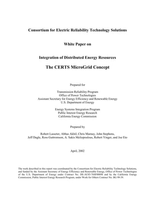
  • 8. 6 3. MicroGrid Structure The MicroGrid structure assumes an aggregation of loads and microsources operating as a single system providing both power and heat. The majority of the microsources must be power electronic based to provide the required flexibility to insure controlled operation as a single aggregated system. This control flexibility allows the MicroGrid to present itself to the bulk power system as a single controlled unit, have plug-and-play simplicity for each microsource, and meet the customers’ local needs. These needs include increased local reliability and security. Key issues that are part of the MicroGrid structure include the interface, control and protection requirements for each microsource as well as MicroGrid voltage control, power flow control, load sharing during islanding, protection, stability, and over all operation. The ability of the MicroGrid to operate connected to the grid as well as smooth transition to and from the island mode is another important function. Feede r A Feede r C Zone-1 PCC Zone-2 Zone-3 Zone-4 Feede r B Zone-5 Zone-6 Energy Manage r Sensitive Loads Traditional Load s SD Powe r & Voltage Con troller Pointof Common Coup ling Breaker Sepa ration Dev ice Zone-7 Heat Load Figure 3.1 MicroGrid Architecture Figure 3.1 illustrates the basic MicroGrid architecture. The electrical system is assumed to be radial with three feeders – A, B, and C – and a collection of loads. The microsources are either Micro- Source
  • 9. 7 microturbines or fuel cells interfaced to the system through power electronics. The Point of Common Coupling (PCC) is on the primary side of the transformer and defines the separation between the grid and the MicroGrid. At this point the MicroGrid must meet the prevailing interface requirements, such as defined in draft standard IEEE P1547. The sources on Feeder A & B allow full exploration of situations where the microsources are placed away from the common feeder bus to reduce line losses, support voltage and/or use its waste heat. Multiple microsources on a radial feeder increase the problem of power flow control and voltage support along the feeder when compared to all sources being placed at the feeder’s common bus, but this placement is key to the plug-and-play concept. The feeders are usually 480 volts or smaller. Each feeder has several circuit breakers and power and voltage flow controllers. The power and voltage controller near each microsource provides the control signals to the source, which regulates feeder power flow and bus voltage at levels prescribed by the Energy Manager. As downstream loads change, the local microsource’s power is increased or decreased to hold the total power flow at the dispatched level. In Figure 3.1 there are two feeders with microsources and one without any generation to illustrate a wide range of options. During disturbances on the bulk power system Feeders A & B can island using the separation device (SD) to minimize disturbance to the sensitive loads. Of course islanding does not make sense if there is not enough local generation to meet the demands of the sensitive loads. The traditional loads on Feeder C are left to ride through the disturbance. This eliminates nuisance trips of the traditional load when the MicroGrid islands to protect critical loads. The MicroGrid assumes three critical functions that are unique to this architecture. • Microsource Controller. The Power and Voltage Controller coupled with the microsource provide fast response to disturbances and load changes without relying on communications. • Energy Manager. Provides operational control through the dispatch of power and voltage set points to each Microsource Controller. The time response of this function is measured in minutes. • Protection. Protection of a MicroGrid in which the sources are interfaced using power electronics requires unique solutions to provide the required functionality. 3.1 Microsource Controller The basic operation of the MicroGrid depends on the Microsource Controller to; regulate power flow on a feeder as loads on that feeder change their operating points; regulate the voltage at the interface of each microsource as loads on the system change; and insure that each microsource rapidly picks up its share of the load when the system islands. In addition to these control functions the ability of the system to island smoothly and to automatically reconnect to the bulk power system is another important operational function. Most of this set of key functions does not exist on currently available microsources. Another important feature of each Microsource Controller is that it responds in milliseconds and uses locally measured voltages and currents to control the microsource during all system or grid
  • 10. 8 events. Fast communication among microsources is not necessary for MicroGrid operation; each inverter is able to respond to load changes in a predetermined manner without data from other sources or locations. This arrangement enables microsources to “plug and play” – that is, microsources can be added to the MicroGrid without changes to the control and protection of units that are already part of the system. The basic inputs to the Microsource Controller are steady-state set points for power, P, and local bus voltage, V. Section 5.0 discusses Microsource Controller in more detail. 3.2 Energy Manager The Energy Manager provides for system operation of the MicroGrid through dispatch of power and voltage set points to each Microsource Controller. This function could be as simple as having a technician enter these set points by hand at each controller to a state-of-the-art communication system with artificial intelligence. The actual values of dispatch of P and V depends on the operational needs of the MicroGrid. Some possible criteria are: • Insure that the necessary heat and electrical loads are met by the microsources; • Insure that the MicroGrid satisfies operational contracts with the bulk power provider; • Minimize emissions and/or system losses; • Maximize the operational efficiency of the microsources; and • et cetera 3.3 Protection The protection coordinator must respond to both system and MicroGrid faults. For a fault on the grid, the desired response may be to isolate the critical load portion of the MicroGrid from the grid as rapidly as is necessary to protect these loads. This provides the same function as an uninterruptible power supply at a potentially lower incremental cost. The speed at which the MicroGrid isolates from the grid will depend on the specific customer loads on the MicroGrid. In some cases, sag compensation can be used to protect critical loads without separation from the distribution system. If a fault occurs within the islandable portion of the MicroGrid, the desired protection is to isolates the smallest possible section of the radial feeder to eliminate the fault. For example a fault in Zone-4, Figure 3.1, could be detected using differential current sensing at the closest Power & Voltage Controller resulting in the operation of the adjacent breaker to isolate the fault with minimum disturbance to the rest of the MicroGrid. Further discussion of the functioning of the protection system is found in Section 6.0. 3.4 Large Systems-Interconnected MicroGrids – Power Parks Because a MicroGrid exploits low voltage, use of waste heat, and the flexibility of power electronics, its practical size may be limited to a few MVA (even though IEEE draft standard P1547 specifies an upper limit of 10MVA). In a large complex, loads could be divided into many controllable units e.g., among buildings or industrial sites. Each unit could be supplied by one or more MicroGrids connected through a distribution system.
  • 11. 9 For example, consider a power park with a total load in excess of 50 MVA. This system could be supplied from the transmission system through one or two substations using 13.8-kV underground cables. Each load group (heat and/or electrical) would be a MicroGrid connected to the 13.8-kV supply. In addition to these MicroGrids, the power park could employ larger generation such as one- to ten-MVA gas turbines directly connected to the 13.8-kV feeder. Each MicroGrid would be a dispatchable load. The power park controls would provide each MicroGrid with its load level (drawing power from the 13.8-kV feeder) while the gas turbines P and Q/V would be dispatched either locally or by the bulk power producer. The advantages of this system are that the MicroGrid structure insures greater stability and controllability, allows for a distributed command and control system, and provides redundancy to insure greater power supply reliability for the power park. 4. MicroGrid Presentation to the Grid The MicroGrid must connect to the grid without compromising grid reliability or protection schemes or causing other problems, consistent with the minimal standards for all connected devices. However, the MicroGrids can offer more value to the grid than simply meeting a doing- no-harm standard i.e. being a good citizen of the grid. MicroGrids can benefit the grid by reducing congestion and other threats to system adequacy if they are deployed as interruptible, or controlled loads that can be partially shed as necessary in response to changing grid conditions. Furthermore, the power electronics in a MicroGrid could also be designed so it behaves like a constant impedance load, a modulated load, or a dispatchable load, to list a few. In addition, MicroGrids could provide local premium power and ancillary services, such as local voltage support, although the low voltage limits its ability to feed into the grid. If the MicroGrid had such features it could be considered a model citizen of the grid. 4.1 Load as a Resource The CERTS MicroGrid can be thought of as a controlled cell of the power system within which heat and power are generated for local customers, and generation and load are controlled. Because joint control of on-site generation, storage, and loads is fundamental to the MicroGrid, grid load could be shed by it in response to system needs. The MicroGrid also could contract to provide firm levels of energy and ancillary services. That is, if schedules permit, the MicroGrid could reduce its load on the grid either by raising the share it generates to meet its own loads or by reducing its load. If the value of the MicroGrid presenting itself as a dispatchable load were taken into account when MicroGrid equipment was installed, essential load-shedding capabilities could be built into the system. Traditional load shedding has been in the form of interruptible contracts or tariffs.2 Typically, a customer agrees to be curtailed up to an agreed number of times and durations. The customer’s reward is either a reduced energy rate that lowers the customer’s overall energy bill or a capacity 2 Load As a Reliability Resource in the Restructured Electricity Market. J. D. Kueck, B. J. Kirby, J. Eto, R. H. Staunton, C. Goldman, C. Marnay, C. Martinez. June, 2001
  • 12. 10 and/or energy payment on the actual load being placed at risk of interruption. Usually, customers are notified by phone, fax, or mobile text messaging, when their service must be interrupted, and verification that the customer load was shed as requested takes place ex post based on meter data. A customer can choose not to comply with the direction to shed load although penalties are often levied for non-compliance and may be severe. A MicroGrid could easily participate in this type of load-shedding program. In some load-curtailment programs, loads are interrupted immediately and without warning. In New Zealand, for example, large numbers of loads have agreed to the installation of under-frequency relays that enable extremely rapid curtailment. A MicroGrid could participate in a similar program if it had the capability to respond by rapidly drawing down storage then increasing its self-generation or reducing its load. Joint, local control of generation and load is at the heart of the MicroGrid concept, which gives a particular meaning to demand-side management. Rather than controlling load for the purpose of adjusting its profile to benefit the wider power system, the MicroGrid controls generation and load together to meet the objectives of MicroGrid customers as economically as possible, which might include participation in interruptible load programs. The key issue for grid reliability is how to offer incentives to MicroGrids to invest and behave in a fashion that enhances grid reliability: e.g., real time pricing or contracts/rate discount options for load curtailment. Load shedding that takes place more rapidly than the electricity commodity market can respond to system conditions (e.g. load curtailment) is a particularly important service that the MicroGrid could offer. 4.2 Dynamic Interactions DER applications are sufficiently small in number at this point so their influence on the stability of the high-voltage transmission system is not an issue. However, if DER became more common, they could have a substantial influence on grid stability. Undesirable dynamic interactions could cause key, heavily loaded transmission lines to trip, interrupting power exports and imports between areas. However, if MicroGrids are designed with their dynamic impact on the transmission system taken into account, they can enhance the stability of transmission lines, which could permit transmission power limits to increase. The question of how much penetration of DER the grid can handle before stability problems result is a not an issue with MicroGrids because they are designed to satisfy their predetermined local load without creating any stability problems for the transmission system.
  • 13. 11 5. Control Methods for MicroGrids Power electronics can provide the control and flexibility for the MicroGrid to meet its customers’ as well as the grid’s needs. MicroGrid controls need to insure that: new microsources can be added to the system without modification of existing equipment, the MicroGrid can connect to or isolate itself from the grid in a rapid and seamless fashion, reactive and active power can be independently controlled, voltage sag and system imbalances can be corrected, and that the MicroGrid can meet the grid’s load dynamics requirements. Microsource Controller techniques described below rely on the inverter interfaces found in fuel cells, microturbines, and storage technologies. A key element of the control design is that communication among microsources is unnecessary for basic MicroGrid operation. Each Microsource Controller must be able to respond effectively to system changes without requiring data from other sources or locations. 5.1 Microsource Control Functions Operation of the MicroGrid assumes that the power electronic controls of current microsources are modified to provide a set of key functions, which currently do not exist. These control functions include the ability to: regulate power flow on feeders; regulate the voltage at the interface of each microsource; ensure that each microsource rapidly pickups up its share of the load when the system islands. In addition to these control functions the ability of the system to island smoothly and automatically reconnect to the bulk power system is another important operational function. Figure 5.1 Interface Inverter System Basic Control of Real and Reactive Power There are two basic classes of microsources: DC sources, such as fuel cells, photovoltaic cells, and battery storage; and high-frequency AC sources such as microturbines, which need to be rectified. In both cases, the DC voltage that is produced is converted using a voltage source inverter. The general model for a microsource is shown in Figure 5.1. It contains three basic elements: prime mover, DC interface, and voltage source inverter. The microsource couples to the MicroGrid using an inductor. The voltage source inverter controls both the magnitude and phase of its output voltage, V. The vector relationship between the inverter voltage, V, and the local MicroGrid voltage, E, along with the inductor’s reactance, X, determines the flow of real
  • 14. 12 and reactive power (P &Q) from the microsource to the MicroGrid. The P & Q magnitudes are coupled as shown in the equations below. For small changes, P is predominantly dependent on the power angle, δp, and Q is dependent on the magnitude of the inverter’s voltage, V. These relationships constitute a basic feedback loop for the control of output power and bus voltage, E, through regulation of reactive power flow. P = 3 2 VE X sinδp Q = 3 2 V X (V − E cosδp) δp = δ V − δ E Voltage Regulation through Droop Integration of large numbers of microsources into a MicroGrid is not possible with basic P-Q controls; voltage regulation is necessary for local reliability and stability. Without local voltage control, systems with high penetrations of microsources could experience voltage and/or reactive power oscillations. Voltage control must insure that there are no large circulating reactive currents between sources. The issues are identical to those involved in control of large synchronous generators. In the power grid, the impedance between generators is usually large enough to greatly reduce the possibility of circulating currents. However, in a MicroGrid, which is typically radial, the problem of large circulating reactive currents is significant. With small errors in voltage set points, the circulating current can exceed the ratings of the microsources. Figure 5.2 Voltage Set Point with Droop This situation requires a voltage vs. reactive current droop controller so that, as the reactive current generated by the microsource becomes more capacitive, the local voltage set point is reduced. Conversely, as the current becomes more inductive, the voltage set point is increased. The function of the basic controller is shown in Figure 5.2. The Q limit shown in the figure is a function of the volts-ampere (VA) rating of the inverter and the power provided by the prime mover.
  • 15. 13 Fast Load Tracking and the Need for Storage A MicroGrid with clusters of microsources and storage could be designed to operate both in isolation and connected to the power grid. When the MicroGrid operates in isolation, load- tracking problems will arise because microturbines and fuel cells respond slowly (time constants range from 10 to 200 seconds) and are inertia-less. Grid power systems currently have storage in the form of generators’ inertia. When a new load comes on line, the initial energy balance is satisfied by the system’s inertia, which results in a slight reduction in system frequency. A MicroGrid cannot rely on generator inertia and must provide some form of storage to insure initial energy balance. MicroGrid storage can come in several forms: batteries or supercapacitors on the DC bus for each microsource; direct connection of AC storage devices (batteries, flywheels etc.); or use of traditional generation with inertia along with microsource generators. For the basic MicroGrid discussed in this paper it is assumed that there is adequate total storage on microsource dc buses to decouple prime mover time delay from the load. If the MicroGrid is not required to operate in island mode, the energy imbalance can be met by the AC system, and storage on the MicroGrid is not necessary. Frequency Droop for Power Sharing (in Islanded Mode of Operation) MicroGrids can provide premium power functions using control techniques where the MicroGrid can island smoothly and automatically reconnect to the bulk power system, much like a UPS system. In island mode, problems such as slight errors in frequency generation at each inverter and the need to change power-operating points to match load changes must be addressed. Power vs. frequency droop functions at each microsource can take care of the problems without the need for a complex communication network. Figure 5.3 Power vs. Frequency Droop Control When the MicroGrid is connected to the grid, MicroGrid loads receive power both from the grid and from local microsources, depending on the customer’s situation. If the grid power is lost because of voltage drops, faults, blackouts, etc., the MicroGrid can transfer smoothly to island operation. When the MicroGrid separates from the grid, the voltage phase angles at each microsource in the MicroGrid change, resulting in an apparent reduction in local frequency. This P01maxP02ma P01P02 ω0 ωmi ω1
  • 16. 14 frequency reduction coupled with a power increase allows for each microsource to provide its proportional share of load without immediate new power dispatch from the Energy Manager. Consider two microsources as in Figure 5.3. In this example, the sources are assumed to have different ratings, P1max, and P2max. The dispatched power in grid mode ( P01 and P02 ) is defined at base frequency, ω0 . The droop is defined to insure that both systems are at rated power at the same minimum frequency. During a change in power demand, these two sources operate at different frequencies, which cause a change in the relative power angles between them. When this change occurs, the two frequencies tend to drift toward a lower, single value for ω1 . Unit 2 was initially operating at a lower power level than Unit 1. However, at the new power level, Unit 2 has increased its share of the total power needs. Because droop regulation decreases the MicroGrid frequency a restoration function must be included in each controller. Droop control design is based on each microsource having a maximum power rating. As a consequence, droop is dependent on the dispatched power level while the microsources are connected to the grid. 5.2 Example System An industrial plant with high motor loads can be used to illustrate the dynamics of the MicroGrid controls presented in the previous section. This industrial site has nearly 1.6 MW of motor load with motors ranging from 50 to 150 hp each; there are also two large synchronous machines. A 120-kV line provides power through a long 13.8-kV feeder consisting of overhead lines and underground cables. The plant has three main feeders; two at 480V and one at 2.4kV. The loads on the 480-V feeders are critical and must continue to be served if grid power is lost. Figure 5.4 Example System, One-Line
  • 17. 15 Details of the plant are shown in Figure 5.4. The induction machine clusters (M8 and M9) are connected to buses 8 and 9 with capacitive voltage support. The machines are modeled as fixed loads with a pf = 0.85. The only dynamics in this model are the power electronics, their controls and the switching events. Two clusters of microsources are also connected to buses 8 and 9 to provide power and voltage support. In the absence of locally generated power, the voltages of buses 8 and 9 are 0.933 and 0.941 per unit (pu, on 480-V base) respectively. Total losses are 70 kW. Each cluster of microsources is rated at 600 KVA and provides both power injection and local voltage support. The microsource power injection is approximately one half the total power. With these sources operating, the voltages on buses 8 and 9 are regulated at 1 pu, and the total losses drop to 6kW, a reduction of 64kW. Figure 5.5 Start-up P & Q of Microsources in Grid-Connected Mode (a) Active Power, (b) Reactive Power Figure 5.6 Regulated voltage (a) bus 8 (b) bus 9 Simulation of grid-connected operation is shown in Figures 5.5 and 5.6. In the initial state, local sources are not generating power, so Figure 5.5 shows zero real and reactive power injection and reduced voltages on buses 8 and 9. At t = one second, the generators at bus 8 are brought on line with a power setting of 446 kW and local voltage control. Note the voltage correction in Figure 5.6(a). At t = three seconds, the units at bus 9 are brought on line with a power set point of 360 kW and local voltage control. Figure 5.5 shows the active and reactive power injections at the buses where units are located. As the second microsource is brought on line, the Q injection at bus 8 to maintain local voltage magnitude drops. Figure 5.6 shows half of the voltage envelope at the regulated buses during the start-up sequence. Voltage on bus 9 is controlled to 1 pu within a few cycles. This example can also be used to simulate island operation with power sharing through droop. It is assumed that the ratings of the microsources are not adequate to supply the total load. The two 480-V feeders supply critical loads, and the M7 load on bus 7 can be dropped using breaker S2 (see Figure 5.4)
  • 18. 16 At t=10 seconds, the MicroGrid moves from grid-connected to island operation by the tripping of switch S1 in response to supply problems (Figure 5.7c). At the same time, the non-critical feeder is dropped using S2. Waveforms for bus 8 and 9 voltages during the switch to island mode are shown in Figures 5.7(a)-(b). There is only a slight change from the sinusoidal steady state; the change lasts less than a cycle Figure 5.8 shows the changes in active and reactive power during the transition. The microsources need to take up the loss of grid power. Both machine clusters increase their power injection as expected from the design of the droop characteristics. The machine with lighter load (Figure 5.3.) at bus 9 increases its output by 56% while the machine on bus 8 increases by 32% to meet the new load demands (see Figure 5.8(a)). Reactive power injection is reduced by 48%, but holds the voltages at 1 pu. Power regulation takes place very rapidly, and steady-state power is restored in fractions of a second. Figure 5.7 Regulated voltages during transfer to island operation (a) bus 8 (b) bus 9 (c) 13.8-kV feeder Figure 5.8 P&Q Transient during Transition from Grid-Connected to Island Operation 6. Protective Relaying and MicroGrids The protective relay design for MicroGrids must be different from what has historically been used for grid distribution systems because MicroGrids add a significant number of electrical sources to a customer’s system, which has historically contained only loads. Some of the differences resulting from this change are obvious; for example, once sources are added, energy can flow in either direction through protection system sensing devices. There are no two- directional flows on most radial systems. A more subtle difference between MicroGrids and traditional grids is that MicroGrids will experience a significant change in short circuit capability when they switch from grid-connected to island operation. This change in short circuit capability will have a profound impact on the vast majority of protection schemes used in today’s systems, which are based on short-circuit current sensing.
  • 19. 17 The protection issues that must be resolved for MicroGrids will be discussed in two scenarios: 1. The first scenario is “normal” operation, in which the MicroGrid is connected to the bulk power provider grid when an event occurs. The protection system must determine the response of the individual DER that make up the MicroGrid, as well as the response of the device that will switch the MicroGrid to island operation. This device is labeled “Separation Device” in Figure 6.1. 2. The second scenario involves an event on the MicroGrid while the MicroGrid is in island operation mode. 6.1 Events Occurring During Normal Operation “Normal operation” in this context means that the MicroGrid is connected to the grid (i.e., the main Separation Device, indicated in Figure 6.1, is closed.) The issues addressed in this operational scenario are the responses of the individual DER and the entire MicroGrid to events on the grid and to events within the MicroGrid. Feede r A Feede r C Zone-1 PCC Zone-2 Zone-3 Zone-4 Feede r B Zone-5 Zone-6 Energy Manage r Sens itive Loads Traditional Load s SD Powe r & Voltage Con troller Pointof Common Coup ling Break er Separation Dev ice Zone-7 Heat Load Figure 6.1.Fa ultson the MicroGrid The appropriate response to an event on the grid will vary depending on the requirements of the MicroGrid loads. For example, if the MicroGrid loads are mainly retail enterprises, the main concern will be to keep the lights on so that businesses can continue serving customers. Any Micro- Source
  • 20. 18 sensitive loads, such as computers associated with cash registers and inventory control, should have dedicated uninterruptible power supply (UPS) systems so that a brief outage (i.e., several seconds) will not affect the enterprise’s capacity to continue with business as usual. If the businesses in the MicroGrid include sensitive loads such as those that are part of many manufacturing lines, the outage times that can be tolerated may be significantly smaller than in the retail customer example above. This is particularly true if the businesses in question participate in the MicroGrid expressly because it provides reliable power supply and thus these customers have not invested in UPSs. If these businesses include semiconductor manufacturers, their equipment may meet the SEMI F47 standard, which has very tight voltage tolerance requirements. These customers will have high expectations of reliability from a MicroGrid. Events on the Grid Events on either side of the transformer or on Feeder C require two responses. The first is opening the Separation Device (“SD”) in Figure 6.1 to island Feeders A & B from the fault. The remaining Zones-1 & 7 represent a traditional system with no distributed generation or special protection provision. As noted above, the rapidity with which isolation must be accomplished to avoid disruption to customers depends on the specific loads on the MicroGrid. The high-speed fault interruption device that is necessary to disconnect the MicroGrid is noted in Figure 6.1 as the Separation Device. Depending on the voltage class, the speed of operation required, and fault current availability, this device may vary from a molded-case circuit breaker with shunt trip to a high-speed static switch. In all cases, a protection scheme will need to be designed for the characteristics of the specific interconnection so that the MicroGrid separation device will trip as needed. This scheme may be relatively simple, such as monitoring current magnitude and direction on each phase and sending a trip signal to the separation device if preset limits are exceeded, or it may be a relatively complex scheme that monitors waveform and attempts to achieve the much-discussed quarter-cycle trip time. The individual DER in the above scenario must have protection schemes that enable them to continue to operate while the sensing and switching takes place disconnecting the MicroGrid from the grid. That is, the event should not trip the DER until the protection scheme has had a chance to separate the MicroGrid from the bulk power producer. If the fault remains on the MicroGrid after disconnection, and the event is determined not to be on the grid, a second set of protective decisions must be made, which will be discussed below. Nuisance (avoidable) separations must also be considered. They will not usually result in loss of load to MicroGrid customers, but they can result in increased costs because of increased operation of the MicroGrid separation device, which will reduce its lifetime and increase labor to restore normal operations. The current draft of IEEE standard P1574 requires separation for certain voltage and frequency perturbations. These requirements are being carefully scrutinized to ensure that adequate protection is provided and nuisance trips are minimized. Events on the MicroGrid While Connected to the Grid From the perspective of the individual DER and individual MicroGrid loads, there is no way to distinguish between an event that occurs on the feeder supplying the MicroGrid that is on the
  • 21. 19 grid side of the MicroGrid disconnecting device and an event that is on the MicroGrid side of this device, as indicated by Zone-2 on Figure 6.1. However, the responses to these two events should be different. As discussed above, the response to the event on the grid side of this device should be to separate the MicroGrid from the grid and maintain normal MicroGrid operation. Note that “maintain normal operation” means keeping loads functional; to accomplish this, the DER control method may need to be altered from the method used while the MicroGrid is grid connected in order to account for the significantly “softer” MicroGrid operation in the absence of grid support. This altered control is discussed in section 5.0. The response to an event on the MicroGrid side of the separation device will include opening the separation device in addition to taking appropriate isolation measures within the MicroGrid. For example, a Zone-2 fault in Figure 6.1 would require opening of the MicroGrid Separation Device as well as opening the two circuit breakers connecting Feeders A & B to the main bus. In the case of a fault within the MicroGrid, separation from the grid should be timed to coordinate with the protection “upstream” (in the direction of the grid source) from the main MicroGrid Separation Device. This coordination will depend on the protection philosophy of the interconnecting grid. Typical coordination might require that the MicroGrid Separation Device trip before any upstream device trips, to minimize the number of customers affected by a particular event. Note that the time required to open the separation device in this case may be different than the time required to open the same device in response to an event on the grid side. In addition to the opening of the MicroGrid Separation Device, it will be necessary to isolate from the rest of the MicroGrid the line segment within the MicroGrid that contains the event, as discussed above for a Zone-2 fault. How this is accomplished will depend on the features and complexity of the MicroGrid. The basic responses of protective devices within the MicroGrid will be the same as those discussed below for the isolated MicroGrid. Resynchronization Finally, once service has been restored to the grid the MicroGrid must have the means to synchronize and reconnect with the grid. Ideally, this should take place as soon as the grid has had an opportunity to pick up all previously disconnected loads and to stabilize, which may require several seconds to several minutes, depending on the nature of the feeder and loads. The MicroGrid must have a control scheme that can bring all DER on the MicroGrid into synchronization with the main bulk power provider, based on measuring the voltage on both sides of the separation device. Whether this resynchronization and reconnection are done automatically or manually may vary depending on the characteristics of the MicroGrid and the interconnecting grid. Resynchronization philosophies and techniques must be studied to determine appropriate approaches. 6.2 Events on the Isolated MicroGrid Consider, as discussed in the preceding section, an event that occurs on the MicroGrid side of the Separation Device. The two Feeders A & B have protection to allow isolation of the minimum number of generators using the line breakers. For example, a Zone-4 fault should activate the nearest breaker isolating the fault with minimum disturbance to the rest of the loads. For a fault
  • 22. 20 in Zone-3 all loads on Feeder A would be isolated and shutdown. Faults in Zone-5 would isolate Feeder B The response of these protective devices within the MicroGrid will vary dramatically depending on the complexity of the MicroGrid. An isolated MicroGrid that contains only one source may be able to employ a protection scheme similar to that used on a conventional radial distribution system. More complex MicroGrids with a number of DER will require more complex protection schemes. Decisions about the cost and complexity of protection schemes will depend on the needs of the MicroGrid. For a MicroGrid in which customers each have adequate DER to serve their own energy needs, protection can be simple: customers can each isolate themselves from the remainder of the MicroGrid in response to an event. However, this protection scenario fails to take advantage of the diversity of load and generation that is possible in a MicroGrid. An approach that more effectively shares the resources of a MicroGrid will necessarily require more complex protection. Zone-3 fault in Figure 6.1, for example, will require that the circuit breaker for Feeder A to trip. As a result, the loads in Zone-3 will not be served (this is unavoidable without individual load UPSs) while those in Zone-4 can remain active. However, the method for detecting Zone-3 is not as straightforward as it might seem because of the dramatically reduced short-circuit current available on the isolated MicroGrid, as will be discussed in the next subsection. Reduced Short-Circuit Current Availability When a fault occurs on the isolated MicroGrid, the MicroGrid’s reduced short-circuit current capability has a significant impact. When the MicroGrid is connected the grid sources could provide fault current that is orders of magnitude greater than load current. This high fault current is easily distinguished from load current and thus is conventionally used to detect faults on radial distribution systems. Most conventional distribution protection is based on short-circuit current sensing. There is a large class of DER – including fuel cells, many microturbines, photovoltaic systems, many wind systems, and battery energy storage systems – that use inverters to interface with the grid. This class of DER may be capable of supplying only twice the load current or less to a fault, so the orders-of-magnitude larger fault current on which conventional overcurrent protection is based is not present. Some overcurrent sensing devices will not even respond to this small amount of overcurrent; those that do respond will take many seconds to do so rather than the fraction of a second that is required. Thus, alternate means of detecting an event must be adopted. There are alternate means available, such as the use of impedance methods, zero sequence current and/or voltage relaying and differential current and/or voltage relaying. The application of these techniques to distribution and customer systems is not well understood and need serious attention. 7. MicroGrid Economics
  • 23. 21 This section addresses some of the economic issues related to MicroGrids. Since the paper takes a medium term view, looking to a paradigm of DER deployment that is a few years to a decade in the future, it attempts to describe some of the more fundamental economic questions that must be addressed. Significant issues at the center of the current policy fray are deliberately skirted. This stance is not intended to suggest that many of the questions at the fore of the current policy debate, e.g. standby charges, net metering, public utility status of the MicroGrid etc., are unimportant. On the contrary, some of the regulatory issues surrounding limits on the ability of small generators to serve loads of neighboring customers clearly crucial, and of course they will have a significant bearing on the viability of DER. However, knowing that the outcome of these debates cannot be foreseen at this time and that the regulatory and business structure of the industry could change significantly over the coming years, it seems inappropriate to focus on them first. The approach taken here is conservative in the sense that it is implicitly assumed that the MicroGrid will have to be viable without the establishment of efficient markets for the various service streams that it may provide, and yet cavalier in that many obvious regulatory barriers are not addressed. It has to be argued that increasing small-scale generation close to loads may be key to expanding power supply because the current centralized power system may not be sustainable. Over the coming decades, construction of new large centralized power generating plants and their associated transmission lines is unlikely to keep pace with the seemingly inexorably growing electricity appetite of the developed world. Environmental concerns, dwindling available sites, and a general NIMBY or BANANA suspicion of power facilities will make the current centralized generating paradigm incapable of adequate expansion.3 Furthermore, based on experience to date, it appears that emerging restructured electricity markets will deliver volatile commodity electricity prices and an erratic investment program that results in unpredictable electricity supply reliability. In short, MicroGrids will not be competing with the centralized power system of today but with the erratic growth of that system in an environment hostile to its expansion. At the same time, customer demand for highly reliable power for vital sensitive equipment is growing and the potential of CHP is one of the few available options for significantly improving overall energy conversion efficiency. The economics or business case for the MicroGrid determines the configuration and operation of the MicroGrid. Issues of MicroGrid economics can be roughly divided into three categories: 1. The first concerns the basic economics of optimal investment and operation of technologies available to the MicroGrid. These are problems that, at least at the distribution system scale, have received intense academic scrutiny; as a result, established and reliable tools are available to guide operations and should, with some adaptation to the specifics of MicroGrids, be effective. In other words, much of our accumulated knowledge about the operation of grid scale systems can be applied to MicroGrids. 2. The second concerns some of the unique aspects of MicroGrids that will require innovation. In general, these are areas in which MicroGrids differ significantly from distribution systems, for example, the possibility of providing heterogeneous levels of reliability to various end 3 NIMBY = not in my backyard, BANANA = build absolutely nothing anywhere near anybody
  • 24. 22 uses, and the critical central importance of some operational constraints, such as noise, that are relatively insignificant to bulk power provider’s economics. 3. The third concerns the relationship of the MicroGrid to the distribution system. In many ways these problems resemble familiar ones related to the interface between customers and utilities, for example, the need to provide a real-time price signal to the MicroGrid so that optimal use of resources by both the MicroGrid and grid can be achieved simultaneously. Other problems are more novel and challenging. For example, MicroGrids’ ability to participate in grid-scale ancillary services markets will most likely be limited by voltage and losses, but MicroGrids could still provide some local services, such as voltage support. Creating a market for localized voltage support, or even placing meaningful value on it, seems unlikely at the present time. 7.1 MicroGrids and Traditional Power System Economics A MicroGrid is designed, installed, and operated by a customer or group of customers primarily for their economic benefit. Although MicroGrid participants may be concerned about the environmental effects of their energy supply system as well as about noise and other similar considerations, the most important benefit that participants seek is a lower total energy bill (i.e., combined bill for heat, electricity, and transportation). The MicroGrid may be able to operate some or all of its end uses at lower cost than would be possible on the grid. The cost of delivered energy from the traditional power system includes losses, customer services, congestion, and other costs that together typically exceed the generation (bus bar) cost alone. The MicroGrid will likely have smaller losses as well as other advantages that will lower its costs relative to the costs of the distribution system. Table 1 shows some present-day cost information for some small-scale generating technologies currently available for deployment in MicroGrids. The first notable feature of Table 1 costs is that on-site generation is currently competitive with central station generation at certain times and in certain places. However, the currently available technology that is apparently cheapest, reciprocating engines, has some pronounced disadvantages, notably air quality impacts (and the associated difficulty of getting related permits), noise, and interconnection costs. During the coming decade, costs of other, new technologies are likely to fall significantly, so that other options, fuel cells for example, may be the cheapest on-site generating technology available under some circumstances. Fuel cells and other types of DER have fewer disadvantages than reciprocating engines. Even without consideration of other benefits of DER, their economics suggest that they will challenge the economies of scale that originally motivated reliance on traditional central station generation. On the other hand, the current system offers low risk and transaction cost to the customer. Without considering for the moment how MicroGrids might be financed and developed, there is no doubt that going the MicroGrid route will incur significant costs that are not seen in the Table 1 representation of equipment costs. While many of these are self-evident, such as the danger of installation cost overruns, some are subtler. For example, it should be noted that for the MicroGrid to operate in island mode as a low inertia system, sources of storage as described in section 5.1 will be required. The total requirement for this equipment is unclear at present, but the costs involved could be significant and this consideration must be brought into the economic evaluation. This additional cost must be traded off against the added
  • 25. 23 benefits of islanding capability from the customer perspective, and against the cost of maintaining high system reliability from the grid perspective. Table 1: Cost Information of Select Generation Technologies *PR = Data considered proprietary Straightforward application of engineering-economic principles can help determine which technologies are likely to be attractive to MicroGrids and how these technologies will be deployed and operated. In many regards, the economics of MicroGrids are similar to those of grid-scale systems. For example, the rules of economic dispatch apply to both, and minimizing costs for both types of systems requires that the lowest-possible-cost combination of resources must be operating at all times, to the extent that equipment characteristics allow. Purchase and sale of electricity is possible in both grid-scale and MicroGrid systems, and both of these activities may occur at different times. The variety of duty cycles required implies that the optimal combination of resources chosen by the MicroGrid will be technologically diverse, like the combinations used in utilities. In this context, technologically diverse resources include those used to meet a range of demands: baseload duty-cycle needs, peak demand, and others degrees of demand between these two extremes. Different types of generators will be most efficient at meeting different types of demand. The classic solution in grid systems is that high- capital, low-variable-cost technologies are suitable for the baseload, and generators with the opposite qualities are suitable for peak demand; this principle could prove equally true for MicroGrids. Although there are numerous similarities between MicroGrid and grid economics, some aspects of traditional MicroGrid economics are novel and will require rethinking or extending familiar tools. Two notable examples are joint optimization of heat and power supply and joint optimization of loads and supply. CHP is a relatively underdeveloped area of power system economics. Use of CHP is common in U.S. industry, and about nine percent of U.S. electricity is currently generated in CHP systems. A major non-industrial application is district-heating systems, which are extensively used in some northern European cities, such as Warsaw. However, these systems have tended to develop in response to isolated opportunities for use of waste heat; until recently, use of heat was not one of the central objectives of grid-scale power system development. A key reason for current rethinking of this issue is the drive to reduce carbon emissions. Increasing the overall efficiency of power generation in the U.S. from the expected approximately 33 percent in 2010 to Name DER Type Source Nameplate lifetime $/kW cost $/kW cost OMFix OMVar Lev Cost Heat Rate kW (a) FOB cost Turnkey cost $/kW/a $/kWh c/kWh kJ/kWh 1 MTL-C-30 MT SCE 30 12.5 1200 1333 119 in Fix O&M 12.14 12,186 2 PAFC-O-200 PAFC TAG 200 12.5 3500 PR PR PR 13.68 PR 3 DE-K-30 Diesel Backup manufacturer 30 12.5 473 1290 26.5 0.000033 5.51 11,887 4 DE-K-60 Diesel Backup manufacturer 60 12.5 290 864 26.5 0.000033 6.30 11,201 5 DE-K-500 Diesel Backup manufacturer 500 12.5 166 386 26.5 0.000033 4.65 10,314 6 DE-C-7 Diesel Backup manufacturer 7.5 12.5 213 627 26.5 0.000033 N/A 10,458 7 DE-C-200 Diesel Backup manufacturer 200 12.5 135 416 26.5 0.000033 4.94 9,944 8 GA-K-55 Gas Backup manufacturer 55 12.5 290 970 26.5 0.000033 7.55 12,997 9 GA-K-500 Gas Backup manufacturer 500 12.5 408 936 26.5 0.000033 7.33 12,003 10 WD-10 Wind Bergey Windpower 10 12.5 2805 6055 5.7 0 27.05 11 PV-5 PV Jeff Oldman, Real Goods 5 20 7150 8650 14.3 0 55.23 12 PV-50 PV Jeff Oldman, Real Goods 50 20 5175 6675 5 0 42.62 13 PV-100 PV Jeff Oldman, Real Goods 100 20 5175 6675 2.85 0 42.62
  • 26. 24 approximately 70 percent could, without fuel switching, provide one half of the approximately 500 Mt overall reduction in total U.S. carbon emissions suggested by the Kyoto Protocol for that year. CHP is the only approach that could deliver power generation efficiency improvements of this magnitude. As a consequence of the scant historic interest in CHP, grids have placed generation stations close to convenient cooling resources rather than at locations that would facilitate use of waste heat. Because one of the driving forces for MicroGrids is the desire to move power generation toward using waste heat, CHP will likely be at the heart of MicroGrid economics. There are three immediately apparent potential applications of CHP in MicroGrids: 1. space heating, domestic hot water heating, and sterilization; 2. industrial or manufacturing processes; and 3. space cooling and refrigeration through use of absorption chilling. To show that the attraction of exploiting CHP opportunities will be a key motivator for customers to self-generate electricity, it is sufficient to show technically feasible examples in which CHP applications of any of the three types can lower the joint cost of providing electricity and heat/cooling relative to the cost of providing these services from separate purchased sources (typically purchased power and natural gas come from the grid). To show that CHP alone is a strong motivator for multiple customers to join together and form MicroGrids, it is also necessary to show that aggregation of heat and power loads has economic benefits. It is not difficult to see that this would be true in certain cases, e.g. a bottling plant with modest space heat and large sterilization loads might optimally produce more electricity that it can by itself consume and would benefit by being part of a MicroGrid. However, a full economic case has not yet been made regarding the degree to which CHP opportunities will motivate customers to form MicroGrids. Joint optimization of demand and supply is a second, key area where some extension of traditional power system economics is required for MicroGrids. In grid-scale systems, control of loads is usually addressed during analysis and planning as demand-side management (DSM), load control, or load shedding and interruptible tariffs or contracts. MicroGrids are different in a number of key respects. First and most importantly, the marginal cost of self-generation at any point in time is well known to and actually paid by the MicroGrid. In other words, for power generated by the MicroGrid, the vagaries of investment cost recovery, cross subsidies, and inaccurate metering and tariffs are all avoided. This is not to say that costs outside the MicroGrid will be well represented in tariffs, environmental rules, etc. The record to date on tariff reform to improve cost signals to customers is pitiful and emergence of the MicroGrid will not change this balance. But within the MicroGrid, the generator and consumer are one and the same decision maker, and the struggle to coordinate investment and operating decisions on what were formally thought of as opposite sides of the meter is eliminated. The MicroGrid can readily know both its marginal cost of providing power at any point in time and the equivalent costs of investments in energy efficiency, and can, with some introspection and analysis, decide what its cost of curtailment is and then can readily trade off the three. This simple reality elevates load control to a new level of importance in MicroGrids and requires an extension of current thinking.
  • 27. 25 7.2 Newer Economic Issues in MicroGrids The second group of economic issues related to MicroGrids covers some unique MicroGrid features that require innovation in traditional power system economics. In general, these are areas in which MicroGrids differ significantly from grid systems, for example, the possibility of providing heterogeneous levels of reliability to various end uses within the MicroGrid, and the central importance of some operational constraints, such as noise, that are relatively insignificant to grid economics. Power systems have traditionally been designed and operated around the concept of “universal service,” which holds that the quality and reliability of power delivered to all customers must meet roughly the same standard. In practice, there are significant deviations from this universal standard, in part because of the problems of serving vast and diverse geographic areas, but the goal is still to adhere to a universal standard. A key motivation of MicroGrids is the desire to move control of power reliability and quality closer to the point of end use so that these properties can be optimized for the specific loads served. Simple economics tells us that tailoring power reliability and quality to the end uses served can deliver benefits simply because, in times of energy shortfall, energy can be moved from lower value end uses to higher value ones. Also, given that providing higher quality and reliability can be assumed to entail some cost, savings will result if higher quality power is not provided to end uses for which it is not required. Traditional power system economics has paid considerable attention to some aspects of valuing power quality and reliability, notably to estimating the cost of general outages and to schemes of priority pricing that would allow customers to exercise choice in their level of reliability; however, the notion that systems could be built around heterogeneous service quality is a quite new. Another related issue (addressed in more detail below) concerns the optimal level of quality for the universal service provided by the grid. If widespread MicroGrids effectively serve sensitive loads with locally controlled generation, backup, and storage, the bulk power system benefits because it is no longer constrained to set its reliability requirements to meet the needs of sensitive local end uses. 7.3 Economic Issues Between MicroGrids and Bulk Power Systems The third set of economic questions related to MicroGrids covers the relationship of MicroGrids to the grid. A fundamental tenet of the MicroGrid paradigm is that the MicroGrid must represent itself to the grid as a good citizen; that is, it must adhere strictly to the rules that apply to all connected devices. The MicroGrid must behave as a legitimate customer or generator or both, and may enhance those traditional economic roles. Delivering true price signals in time and space raises some significant problems. Because MicroGrids embed new generation within the existing radial distribution system, system upgrades that would otherwise be necessary to meet growing load can be postponed or entirely avoided. Ideally a price signal could be delivered to customers within the distribution system at times of increasing congestion in a form that would encourage MicroGrid development and investment in generation and/or load control to mitigate the congestion. However, this is difficult in practice. The design of distribution systems in densely populated areas is quite
  • 28. 26 flexible so that any one end-use load could be served by several alternative system configurations. Thus, the congestion costs seen by any one MicroGrid would depend on a somewhat arbitrary configuration of the network that could change abruptly, thus disrupting the economics dependent on that configuration. MicroGrid participation in markets is both possible and desirable, but there are some likely limits to it. The low voltages of the MicroGrid will inhibit its ability to efficiently deliver energy beyond the substation, and provision of ancillary services will be similarly limited. One service that the MicroGrid can readily provide, however, is interruptible load, taking advantage of its on- site generation and control schemes to protect sensitive loads. This could be a valuable contribution to the overall health of the power system as market responses to load changes become less and less feasible when response times must be within seconds or minutes. 8. Conclusion The Consortium for Electric Reliability Technology Solutions is pioneering the concept of MicroGrids as an alternative approach to integrating small scale distributed energy resources into electricity distribution networks, and more generally, into the current wider power system. Traditional approaches focus on minimizing the consequences for safety and grid performance of a relatively small number of individually interconnected microgenerators, implying, for example, that safety requires they instantaneously disconnect in the event of system outage. By contrast, MicroGrids would be designed to operate independently, usually operating connected to the grid but islanding from it, as cost effective or necessary to maintain performance. A MicroGrid is a semiautonomous grouping of generating sources and enduse sinks that are placed and operated for the benefit of its member customer(s). The supply sources may be driven by a diverse set of prime movers and/or storage devices. The key distinguishing feature of the MicroGrid is that sources are interconnected by Microsource Controllers. These power electronic devices maintain energy balance and power quality through passive plug and play power electronic inverter features that allow operation without tight central active control or fast (on time scales less than minutes) communication. They also permit connection and disconnection of devices without need for any reconfiguration of equipment, preexisting or new. Overall economic operation within constraints such as air quality permit restrictions, noise limits, etc., as well as maintenance of a legitimate façade to the grid is achieved entirely through slow (on time scales of minutes or longer) communications with a central Energy Manager. A critical feature of the MicroGrid is its presentation to the surrounding distribution system as a single controlled system, akin to a current customer, or possibly a small generation source. Key to this characteristic is reliance on the flexibility of advanced power electronics that control the interface between microsources and their surrounding AC system. The MicroGrid architecture ensures that its electrical impact on the distribution grid at least ensures it to be a good citizen, that is one that does no harm. In some circumstances, it may qualify as a model citizen, that is one that adds benefits to the grid such as reducing congestion, offsetting the need for new generation, supplying local voltage support, enhancing stability, or responding to rapid changes in load levels.
  • 29. 27