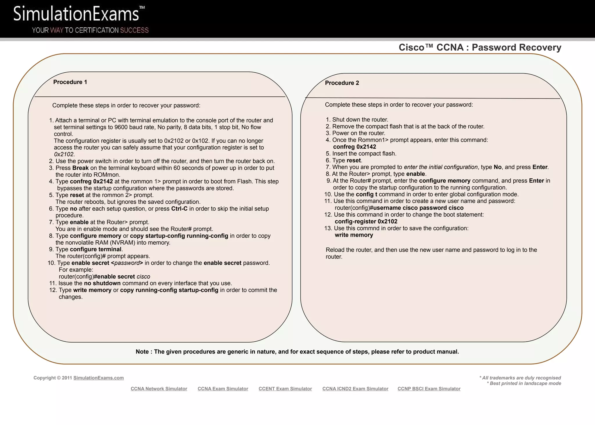
The document discusses Cisco CCNA topics including the OSI and TCP/IP models, Cisco IOS, IPv4 addressing, subnetting, and password recovery procedures.
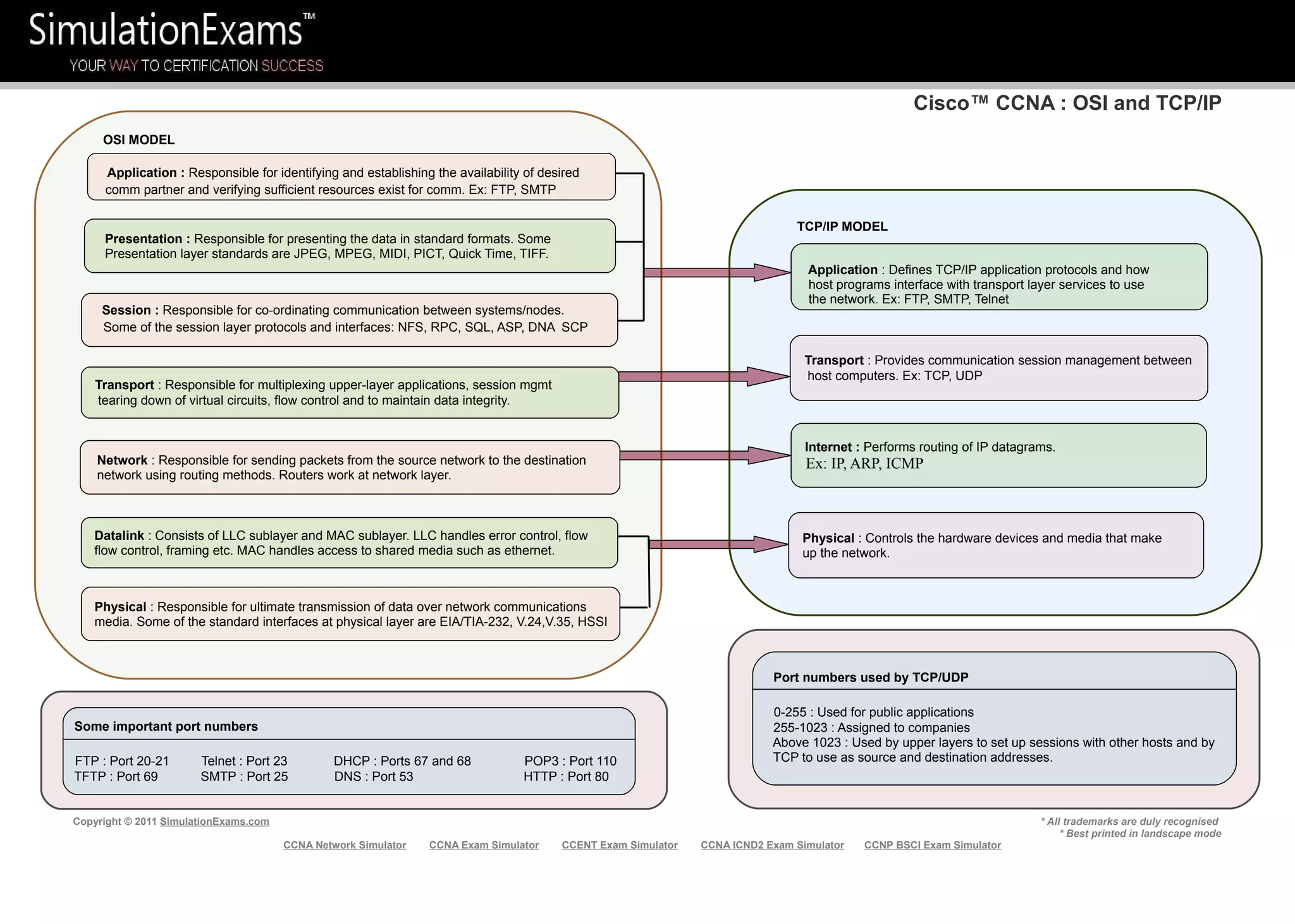
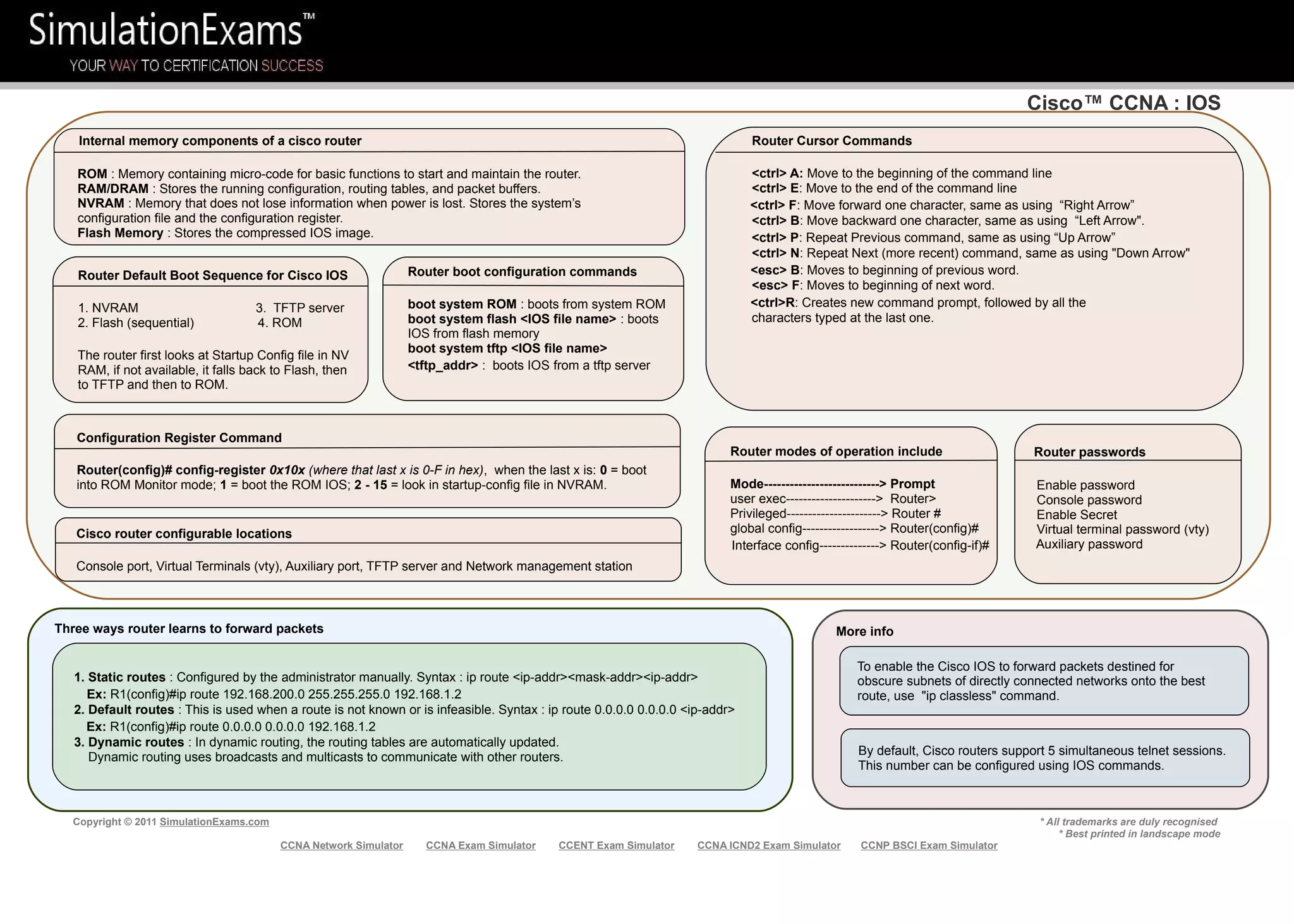
It provides details on each layer of the OSI and TCP/IP models, components of a Cisco router like ROM, RAM, NVRAM, and flash memory. It also covers Cisco IOS boot commands, router modes, and cursor commands.
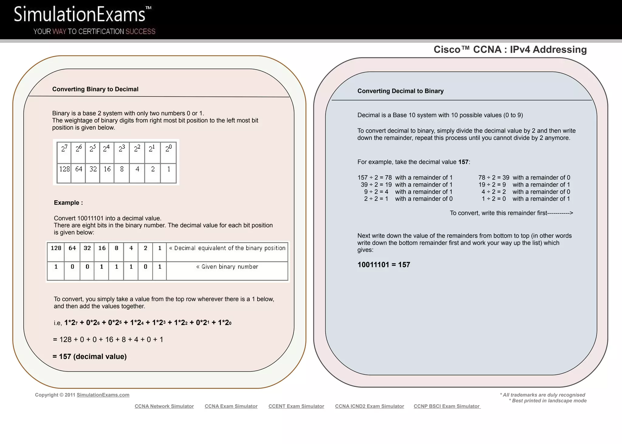
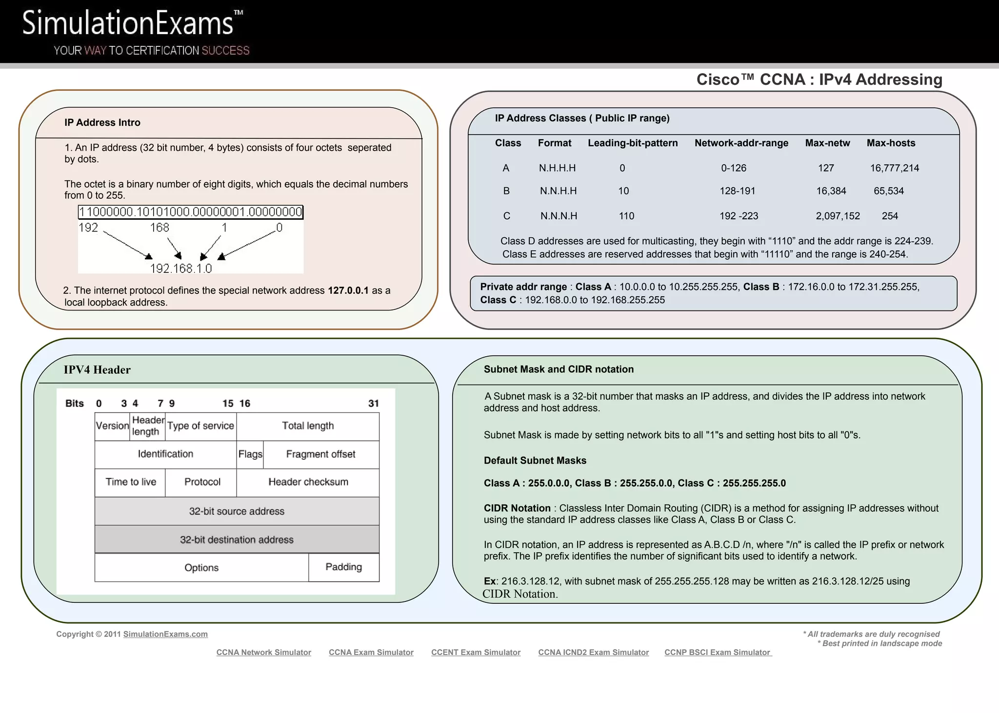
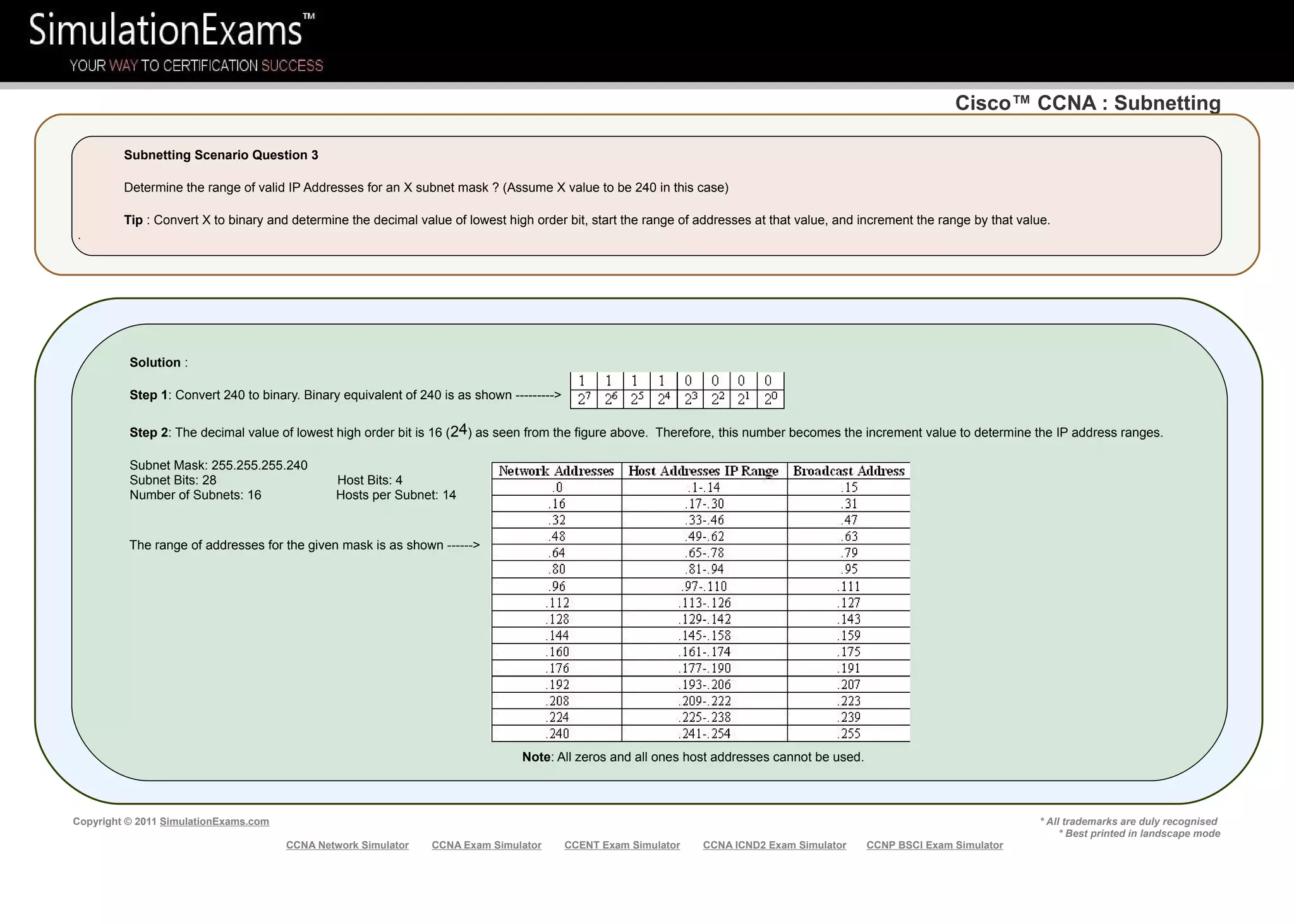
The document also explains IPv4 addressing fundamentals like address classes, private addressing, subnet masks, CIDR notation, and provides examples of converting between binary and decimal.
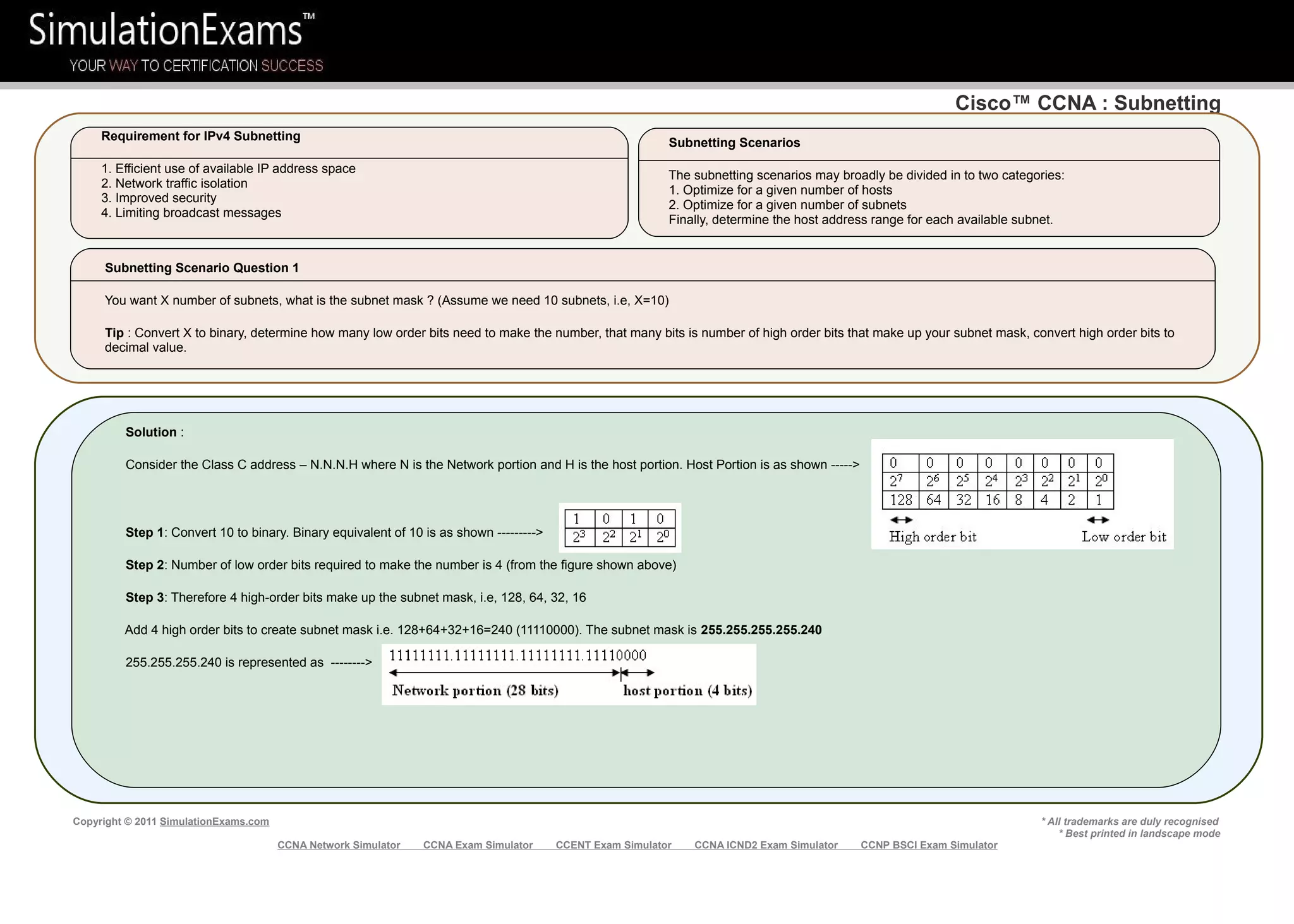
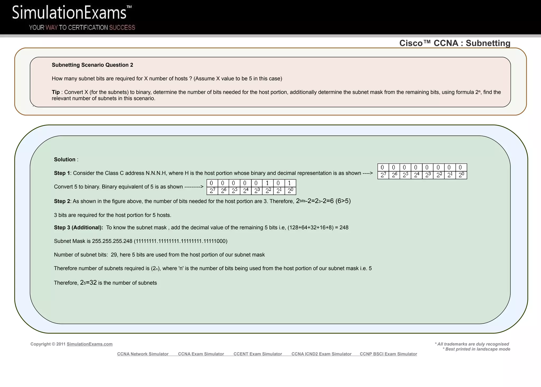
Finally, it discusses subnetting concepts and provides examples of determining subnet masks and number of subnets based on given host or subnet requirements
![cvcccccCisco
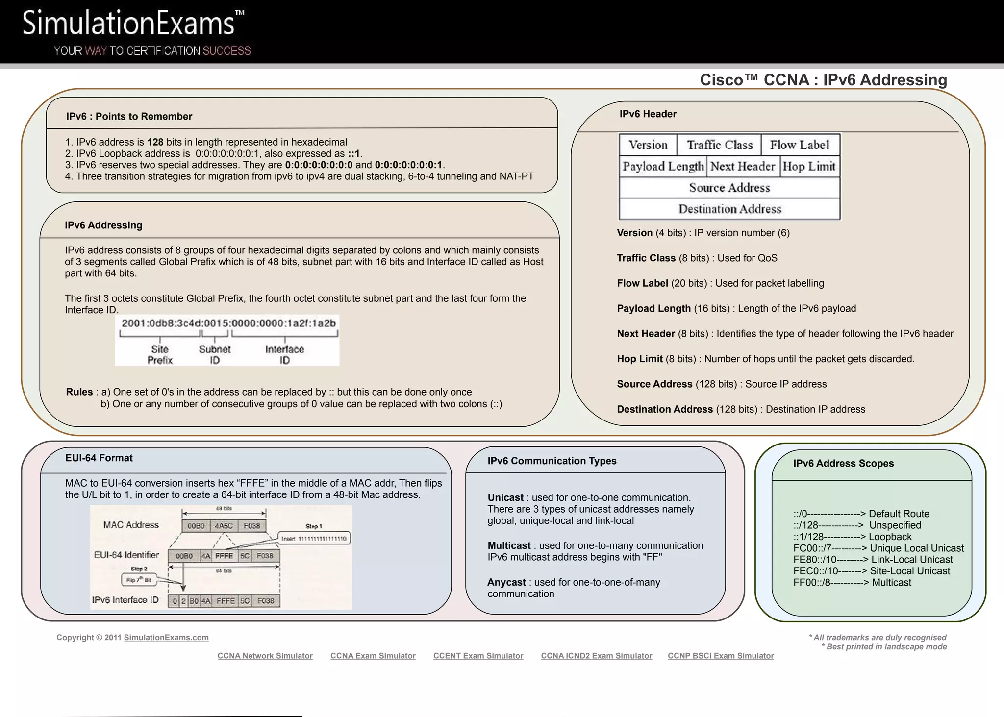
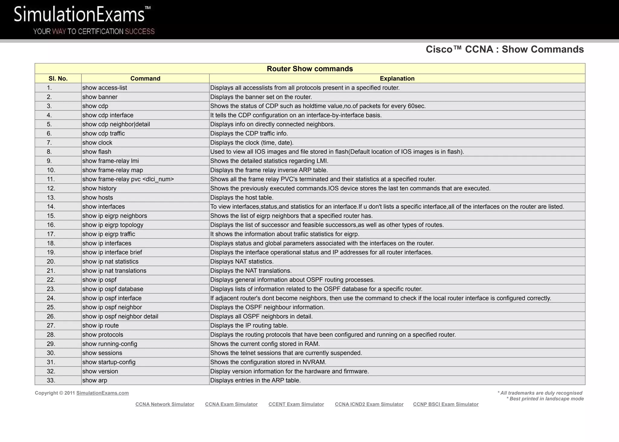
Cisco™ CCNA : Access-Lists
Copyright © 2011 SimulationExams.com * All trademarks are duly recognised
* Best printed in landscape mode
CCNA Network Simulator CCNA Exam Simulator CCENT Exam Simulator CCNA ICND2 Exam Simulator CCNP BSCI Exam Simulator
Access Lists
IP access lists are a sequential list of permit and deny conditions that apply to IP addresses or upper
layer protocols. Access Control Lists are used in routers to identify and control traffic.
Purpose of Access Lists
1. Controlling traffic through a router, and
2. Controlling VTY access to a router’s VTY
ports
3. Filter incoming and outgoing packets
4. Restrict contents of routing updates
5. Trigger dial-on-demand routing (DDR) calls
Types of IP Access Lists
Standard IP Access Lists
Extended IP Access Lists
Named Access Lists
Wild Card Masking
Wild card masking is used to permit or deny a group of addresses.
For example, if we have a source address 185.54.13.2 and want all the
hosts on the last octet to be considered, we use a wild card mask,
185.54.13.255.
The 32 bit wildcard mask consists of 1’s and 0’s
1 = ignore this bit
0 = check this bit
Special Case: Host 185.54.13.2 is same as 185.54.13.2 with a wild card
mask of 0.0.0.0, considers only specified IP.
Any is equivalent to saying 0.0.0.0 with a wild card mask of
255.255.255.255. This means none of the bits really matter. All IP
addresses need to be considered for meeting the criteria.
Standard Access List
1. These have the format, access-list [number] [permit or deny] [source_address]
Ex: access-list 1 permit 192.168.2.0 0.0.0.255
2. Place standard access lists as near the destination as possible and extended access lists
as close to the source as possible.
3. Access lists have an implicit deny at the end of them automatically. Because of this, an
access list should have at least one permit statement in it; otherwise the access list will
block all remaining traffic.
4. Access lists applied to interfaces default to outbound if no direction is specified.
Extended Access Lists and Named Access Lists
Extended Access lists have the format,
access-list {number}{permit or deny} {protocol} {source}source-wildcard [operator
[port]]{destination} destination-wildcard [operator [port]]
With extended IP access lists, we can act on any of the following:
- Source address - Port information (WWW, DNS, FTP, etc.)
- Destination address
- IP protocol (TCP, ICMP, UDP, etc.)
Ex: access-list 101 permit icmp host 192.168.3.2 any
Named Access lists have the format, ip access-list {standard /extended} name
Ex: ip access-list extended denyping
Permitted numbers for access-lists
1-99: IP standard access list 100-199: IP extended access list 800-899: IPX standard access list
1000-1099: IPX SAP access list 1100-1199: Extended 48-bit MAC address access list 900-999: IPX extended access list](https://image.slidesharecdn.com/ccna-cheatsheet-130425232005-phpapp02/75/Ccna-cheat-sheet-12-2048.jpg)
![cvcccccCisco
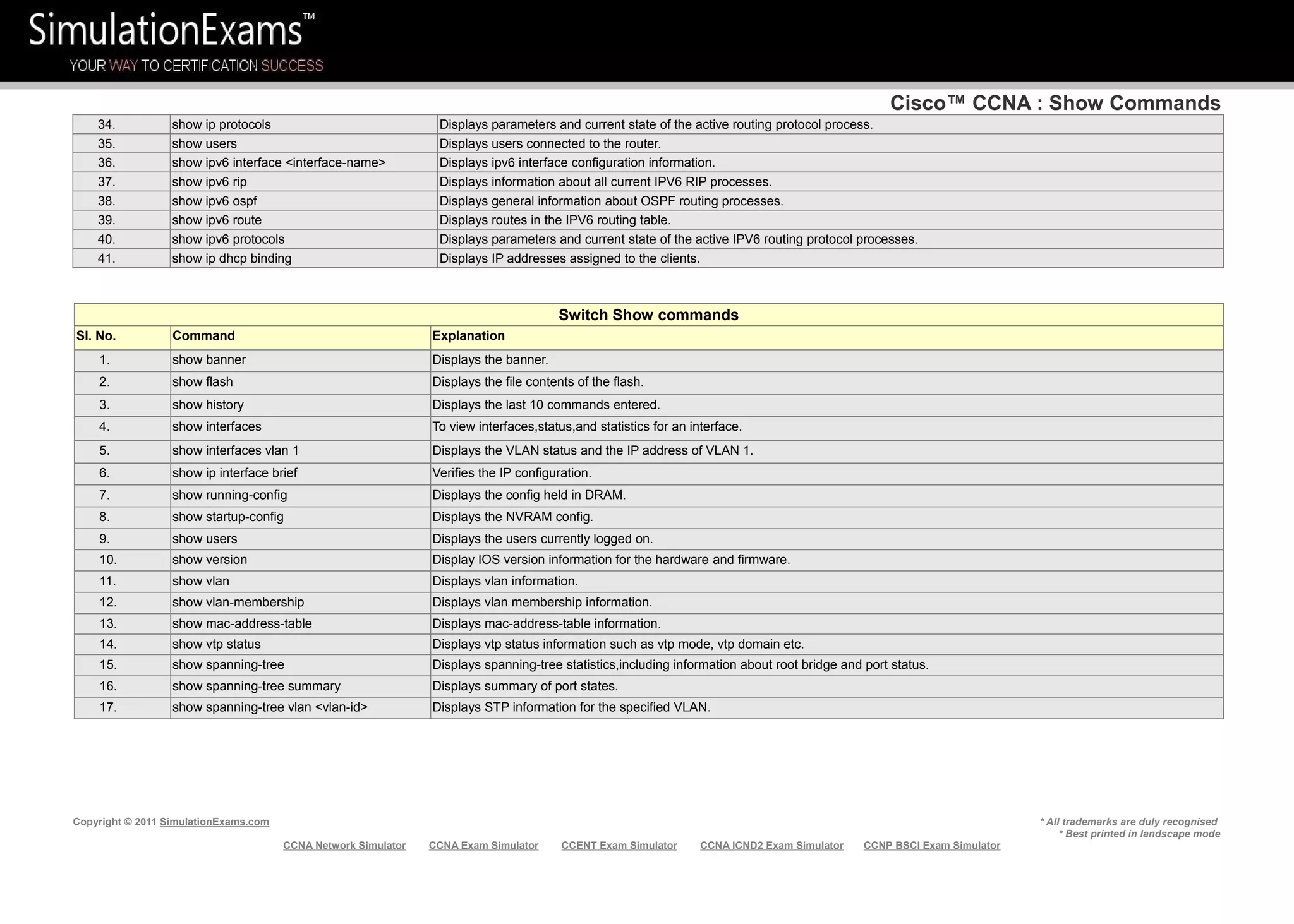
Cisco™ CCNA : NAT
Copyright © 2011 SimulationExams.com * All trademarks are duly recognised
* Best printed in landscape mode
CCNA Network Simulator CCNA Exam Simulator CCENT Exam Simulator CCNA ICND2 Exam Simulator CCNP BSCI Exam Simulator
Overloading
A special case of dynamic NAT that maps multiple unregistered IP addresses to a single registered (globally
unique) IP address by using different port numbers.
Dynamic NAT with overloading is also known also as PAT (Port Address Translation).
Static NAT
Maps an unregistered IP address to registered IP (globally unique) addresses on one-to-one basis.
The command, ip nat inside source static <local ip> <global ip> configures address translation for
static NAT.
Configuring NAT
When configuring NAT, NAT should be enabled on at least
one inside and one outside interface.
1. The command for enabling NAT on inside interface is:
R1(config-if)#ip nat inside
2. The command for enabling NAT on the outside interface
is:
R1(config-if)#ip nat outside
Remember to enter into appropriate configuration modes
before entering the commands.
Usually, the inside NAT will be configured on an Ethernet
interface, whereas the outside NAT is configured on a
serial interface.
Address Classification
Inside Local : An actual address assigned to an inside host
Inside Global : An inside address seen from the outside
Outside Global : An actual address assigned to an outside host
Outside Local : An outside address seen from the inside
NAT Pool : A pool of IP addresses to be used as inside global or
outside local addresses in translations
Defining an IP NAT Pool
1. Defining an IP NAT pool for the inside network using the command:
ip nat pool <pool-name> <start-ip> <end-ip> {netmask <net-mask> | prefix-length <prefix-length>} [type-
rotary] Ex: ip nat pool pool1 200.200.200.3 200.200.200.4 netmask 255.255.255.0
Note that type-rotary is optional command. It indicates that the IP address range in the address pool identifies
hosts among which TCP load is distributed.
2. Mapping the access-list to the IP NAT pool by using the command:
ip nat inside source list <access-list-number> pool <pool-name> Ex: ip nat inside source list 1 pool pool1
Dynamic NAT
Maps an unregistered IP address to a registered (globally unique) IP address from a group of registered
(globally unique) IP addresses.
The command, ip nat inside source list <access-list-number> pool <name>
is used to map the access-list to the IP NAT pool during the configuration of Dynamic NAT.
Overlapping
This occurs when your internal IP addresses belong to global IP address range that belong to another
network.](https://image.slidesharecdn.com/ccna-cheatsheet-130425232005-phpapp02/75/Ccna-cheat-sheet-13-2048.jpg)


![[CONFidence 2016]: Alex Plaskett, Georgi Geshev - QNX: 99 Problems but a Micr...](https://cdn.slidesharecdn.com/ss_thumbnails/alexplaskettgeorgigeshev-qnx99problems-160601111108-thumbnail.jpg?width=640&height=640&fit=bounds)