Downloaded 342 times

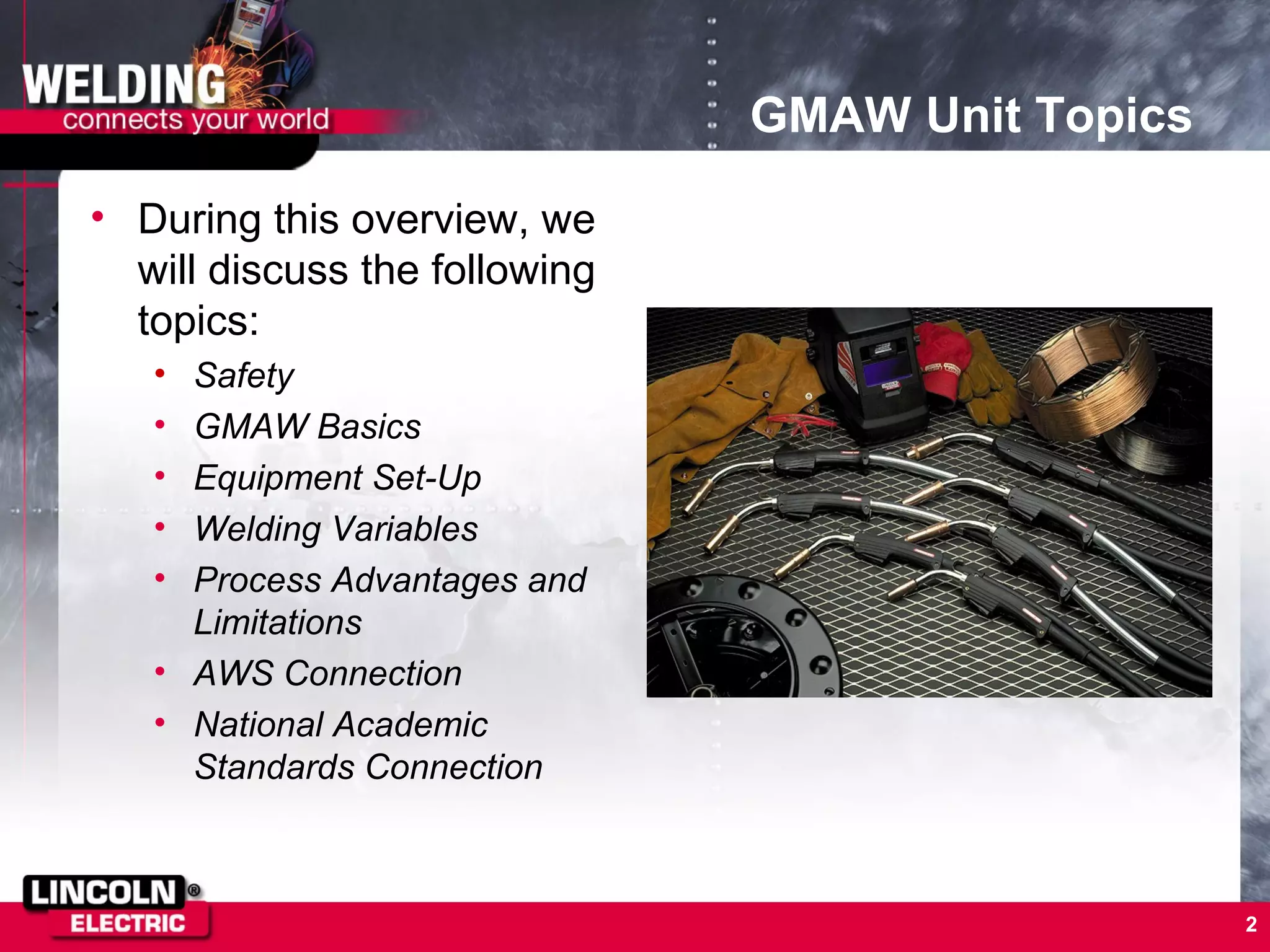


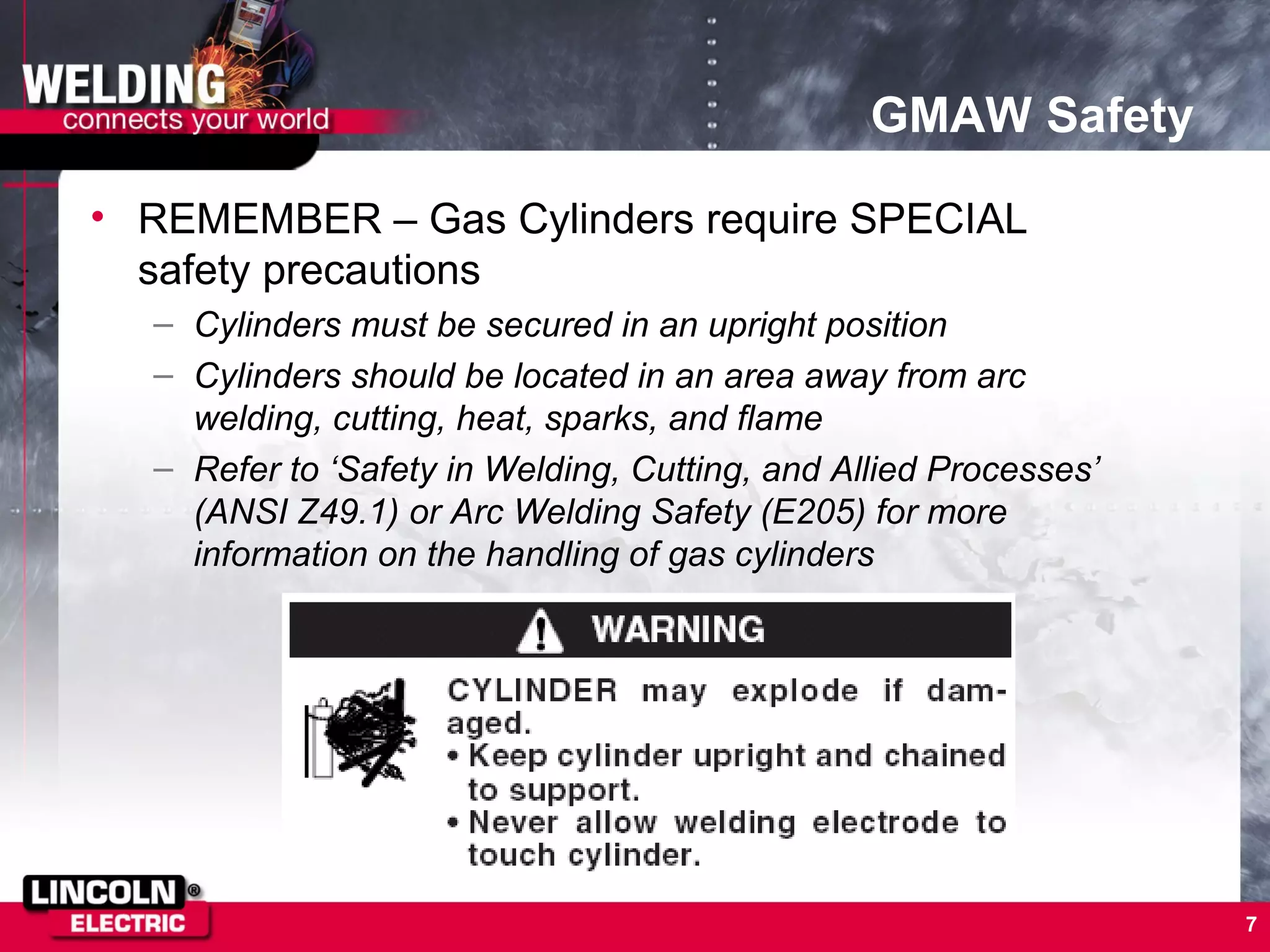

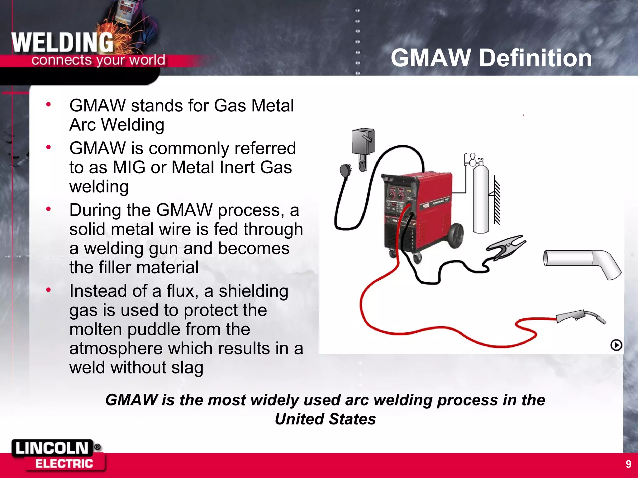


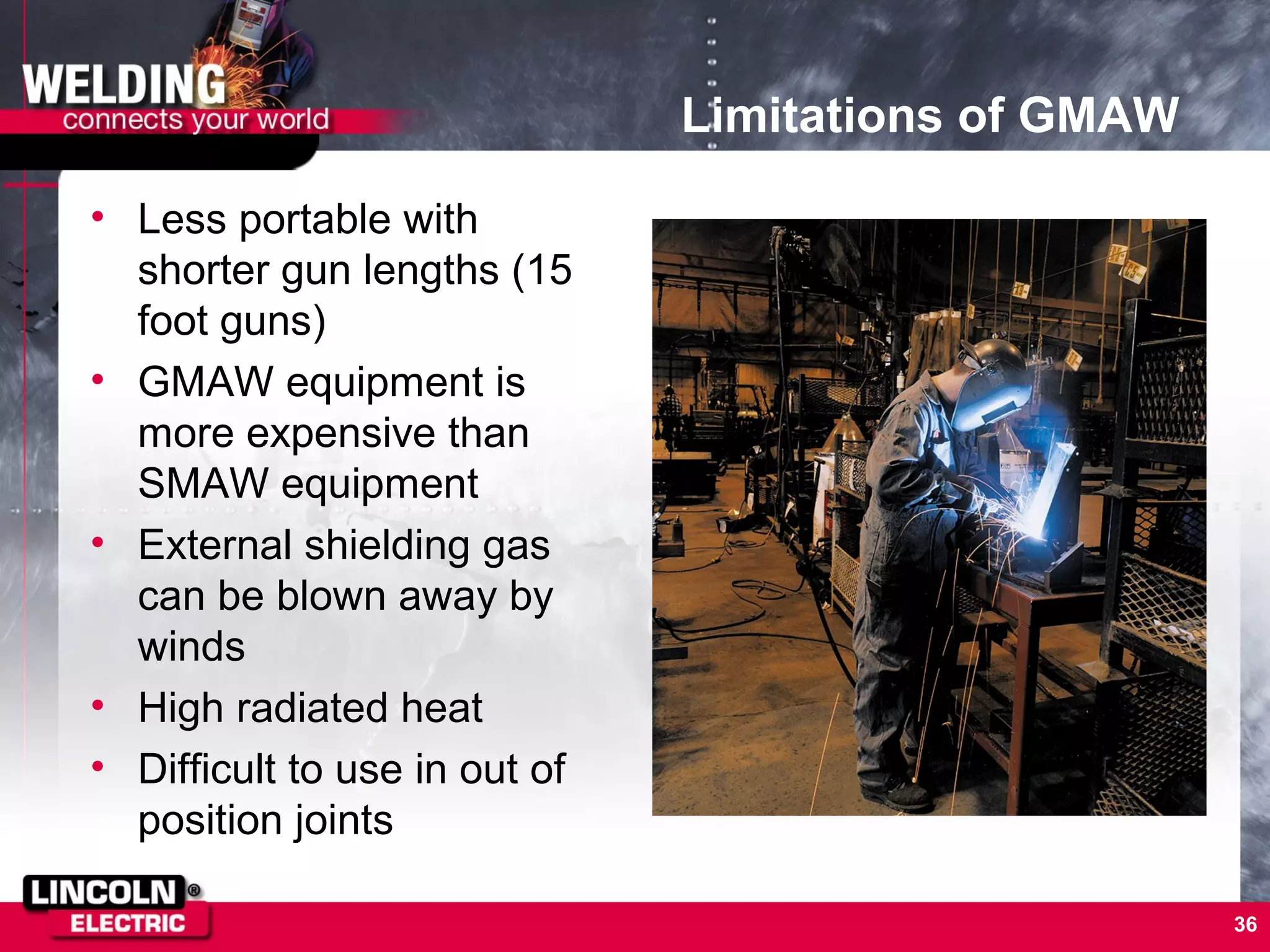


The document provides information on gas metal arc welding (GMAW or MIG welding). It discusses GMAW safety, principles, equipment setup, process variables, modes of metal transfer, troubleshooting welds, advantages and limitations. It also outlines three sample GMAW lesson plans focused on running stringer beads, making fillet welds on lap joints, and making fillet welds on tee joints.