Outline
• Distribution systemcomponents
• Line repairs
• Valves, hydrants, service lines, water meters
• Corrosion
• Maintenance
• Asset management
• Water loss and leak detection
• Cross-connections
Types of Pipes
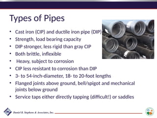
•Cast iron (CIP) and ductile iron pipe (DIP)
• Strength, load bearing capacity
• DIP stronger, less rigid than gray CIP
• Both brittle, inflexible
• Heavy, subject to corrosion
• CIP less resistant to corrosion than DIP
• 3- to 54-inch-diameter, 18- to 20-foot lengths
• Flanged joints above ground, bell/spigot and mechanical
joints below ground
• Service taps either directly tapping (difficult!) or saddles
6.
Types of Pipes(continued)
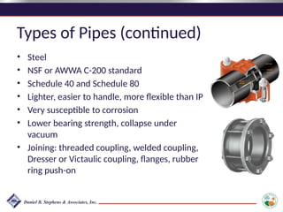
• Steel
• NSF or AWWA C-200 standard
• Schedule 40 and Schedule 80
• Lighter, easier to handle, more flexible than IP
• Very susceptible to corrosion
• Lower bearing strength, collapse under
vacuum
• Joining: threaded coupling, welded coupling,
Dresser or Victaulic coupling, flanges, rubber
ring push-on
7.
Types of Pipes(continued)
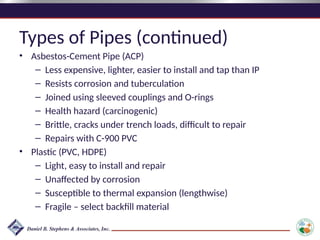
• Asbestos-Cement Pipe (ACP)
– Less expensive, lighter, easier to install and tap than IP
– Resists corrosion and tuberculation
– Joined using sleeved couplings and O-rings
– Health hazard (carcinogenic)
– Brittle, cracks under trench loads, difficult to repair
– Repairs with C-900 PVC
• Plastic (PVC, HDPE)
– Light, easy to install and repair
– Unaffected by corrosion
– Susceptible to thermal expansion (lengthwise)
– Fragile – select backfill material
8.
Corrosion
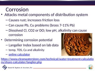
• Attacks metalcomponents of distribution system
– Causes rust; increases friction loss
– Can cause Pb, Cu problems (brass 7-11% Pb)
– Dissolved Cl, CO2 or DO; low pH, alkalinity can cause
corrosion
• Determining corrosion potential
– Langelier Index based on lab data
– temp, TDS, Ca and alkalinity
– online calculator
https://www.cleanwaterstore.com/technical/water-treatment-calculatio
ns/share-calculater/langlier.php
9.
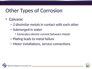
Other Types ofCorrosion
• Galvanic
– 2 dissimilar metals in contact with each other
– Submerged in water
• Generates electric current between metals
– Plating leads to metal failure
– Meter installations, service connections
10.
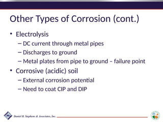
Other Types ofCorrosion (cont.)
• Electrolysis
– DC current through metal pipes
– Discharges to ground
– Metal plates from pipe to ground – failure point
• Corrosive (acidic) soil
– External corrosion potential
– Need to coat CIP and DIP
11.
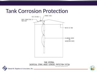
Cathodic Protection
cathodic protection- the prevention of
electrolytic corrosion in something metallic such
as an underground pipe or a ship by making it
the cathode in an electrolytic cell
Which components do you think might need
cathodic protection?
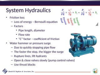
System Hydraulics
• Frictionloss
– Loss of energy – Bernoulli equation
– Factors
• Pipe length, diameter
• Flow rate
• “C” factor – coefficient of friction
• Water hammer or pressure surge
– Due to quickly stopping pipe flow
– The faster the stop, the bigger the surge
– Rupture lines, lift hydrants
– Open & close valves slowly (pump control valves)
– Use thrust blocks
15.
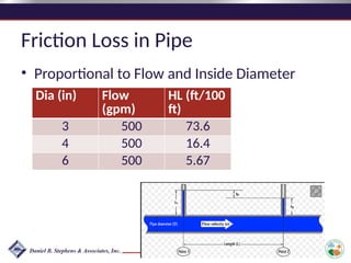
Friction Loss inPipe
• Proportional to Flow and Inside Diameter
Dia (in) Flow
(gpm)
HL (ft/100
ft)
3 500 73.6
4 500 16.4
6 500 5.67
16.
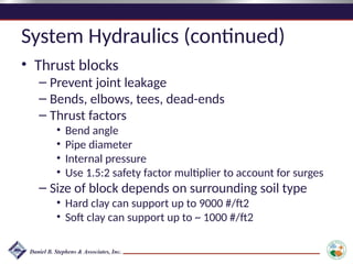
System Hydraulics (continued)
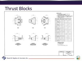
•Thrust blocks
– Prevent joint leakage
– Bends, elbows, tees, dead-ends
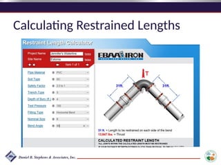
– Thrust factors
• Bend angle
• Pipe diameter
• Internal pressure
• Use 1.5:2 safety factor multiplier to account for surges
– Size of block depends on surrounding soil type
• Hard clay can support up to 9000 #/ft2
• Soft clay can support up to ~ 1000 #/ft2
17.
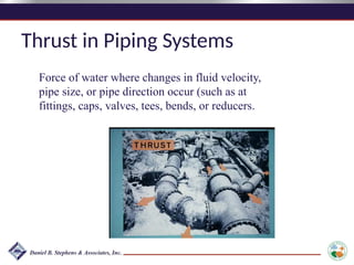
Thrust in PipingSystems
Force of water where changes in fluid velocity,
pipe size, or pipe direction occur (such as at
fittings, caps, valves, tees, bends, or reducers.
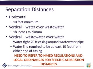
Separation Distances
• Horizontal
–10 feet minimum
• Vertical – water over wastewater
– 18 inches minimum
• Vertical – wastewater over water
– Water-tight 20 ft casing around wastewater pipe
– Water line required to be at least 10 feet from
either end of casing
NEED TO REFER TO NMED REGULATIONS AND
LOCAL ORDINANCES FOR SPECIFIC SEPARATION
DISTANCES
22.
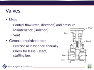
Valves
• Uses
– Controlflow (rate, direction) and pressure
– Maintenance (isolation)
– Vent
• General maintenance
– Exercise at least once annually
– Check for leaks – stem,
stuffing box
23.
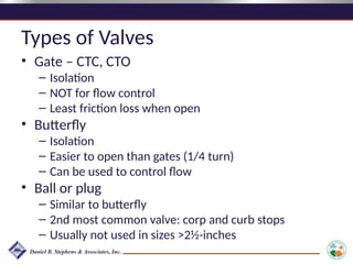
Types of Valves
•Gate – CTC, CTO
– Isolation
– NOT for flow control
– Least friction loss when open
• Butterfly
– Isolation
– Easier to open than gates (1/4 turn)
– Can be used to control flow
• Ball or plug
– Similar to butterfly
– 2nd most common valve: corp and curb stops
– Usually not used in sizes >2½-inches
24.
Types of Valves(continued)
• Check
– Swing in horizontal; lift in vertical
– Discharge side of pumps; foot valves
• Air release
– Vent
• Globe
– Flow control (2-way)
– Mixing (3-way)
– Hydraulically operated, diaphragm-actuated
25.
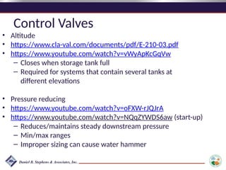
Control Valves
• Altitude
•https://www.cla-val.com/documents/pdf/E-210-03.pdf
• https://www.youtube.com/watch?v=vWyApKcGqVw
– Closes when storage tank full
– Required for systems that contain several tanks at
different elevations
• Pressure reducing
• https://www.youtube.com/watch?v=oFXW-rJQJrA
• https://www.youtube.com/watch?v=NQqZYWDS6aw (start-up)
– Reduces/maintains steady downstream pressure
– Min/max ranges
– Improper sizing can cause water hammer
26.
Control Valves
• Pressurerelief
• https://www.youtube.com/watch?v=bvp7Zqls7Fw
– Provide protection against high pressures that may develop
– Used in conjunction with pressure reducer
– Acts as by-pass (cross-connection potential)
• Pressure sustaining
• https://www.youtube.com/watch?v=rOKJokoWttM
– Throttles (restricts) flow to maintain user-defined upstream
pressure
– Upstream pressure increases
– Downstream pressure decreases
– Example; maintaining pressure in upstream multistory building
27.
Hydrants
• Fire insurancerates
– Maximum 500 to 600 feet residential spacing
– Minimum 6-inch lines
– Dead ends
– Operated every 6 months, flow tested annually
• Other uses
– Flush, vent lines
– Pressure and flow testing
28.
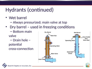
Hydrants (continued)
• Wetbarrel
– Always pressurized; main valve at top
• Dry barrel – used in freezing conditions
– Bottom main
valve
– Drain hole –
potential
cross-connection
29.
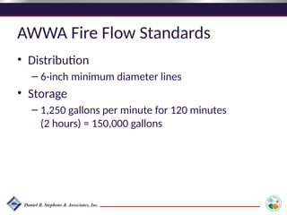
AWWA Fire FlowStandards
• Distribution
– 6-inch minimum diameter lines
• Storage
– 1,250 gallons per minute for 120 minutes
(2 hours) = 150,000 gallons
30.
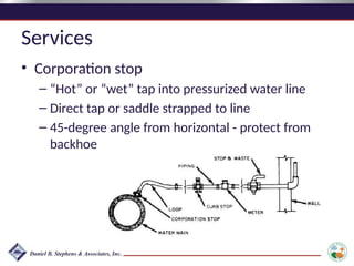
Services
• Corporation stop
–“Hot” or “wet” tap into pressurized water line
– Direct tap or saddle strapped to line
– 45-degree angle from horizontal - protect from
backhoe
31.
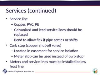
Services (continued)
• Serviceline
– Copper, PVC, PE
– Galvanized and lead service lines should be
replaced
– Bend to allow flex if pipe settles or shifts
• Curb stop (copper shut-off valve)
– Located in easement for service isolation
– Meter stop can be used instead of curb stop
• Meters and service lines must be installed below
frost line
32.
Service Meters
• “CashRegisters”
• Worn or broken meters under-register flow
• Test a selection of customer meters annually:
– Recalibrate
– Repair
– Replace
• Accuracy for most meters should be +/- 1.5
percent
33.
Types of ServiceMeters
• Positive displacement
– Most common; applications up to 2 inches
– Fill/empty cycle of calibrated chamber
– Displaces disc (nutating) or oscillating piston
– Disc or piston action transferred to head by
gears or magnetic drives
34.
Types of ServiceMeters (cont.)
• Turbine or rotor
– 5/8” and larger, low pressure applications
– Dependable with relatively low head loss
– Water velocity proportional to turbine rotation
– Turbine shaft connected to meter register
– Multi-jet meters for low flow applications
35.
Types of ServiceMeters (cont.)
• Venturi
– High flow applications
– Measures difference in pressure head at throat
(conservation of energy, Bernoulli equation)
– Low head loss; very dependable (no moving
parts)
36.
Types of ServiceMeters (cont.)
• Compound meter
– Two-in-one meters
– Displacement meter for low flows
– Turbine meter for higher flows
• Magnetic Meters
– No moving parts
– Applies a magnetic field – measures
potential difference
37.
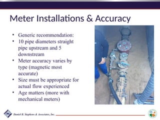
Meter Installations &Accuracy
• Generic recommendation:
• 10 pipe diameters straight
pipe upstream and 5
downstream
• Meter accuracy varies by
type (magnetic most
accurate)
• Size must be appropriate for
actual flow experienced
• Age matters (more with
mechanical meters)
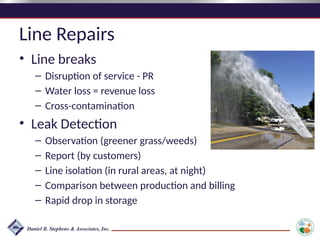
Line Repairs
• Linebreaks
– Disruption of service - PR
– Water loss = revenue loss
– Cross-contamination
• Leak Detection
– Observation (greener grass/weeds)
– Report (by customers)
– Line isolation (in rural areas, at night)
– Comparison between production and billing
– Rapid drop in storage
40.
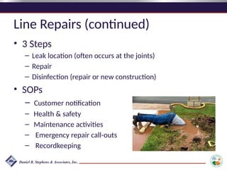
Line Repairs (continued)
•3 Steps
– Leak location (often occurs at the joints)
– Repair
– Disinfection (repair or new construction)
• SOPs
– Customer notification
– Health & safety
– Maintenance activities
– Emergency repair call-outs
– Recordkeeping
41.
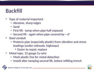
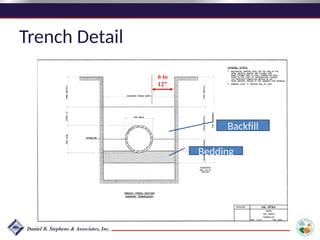
Backfill
• Type ofmaterial important
– Abrasive, sharp edges
– Sand
– First lift - tamp when pipe half exposed
– Second lift - again when pipe covered by ~ 6”
• Steel conduit
– Protects pipe (especially plastic) from vibration and stress
loadings (under railroads, highways)
• Easier to repair, replace
• Metal tape, 12-gauge Cu wire
– Mark plastic line for metal detection
– Install after tamping second lift, before refilling trench
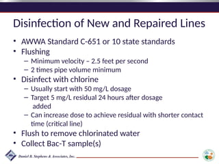
Disinfection of Newand Repaired Lines
• AWWA Standard C-651 or 10 state standards
• Flushing
– Minimum velocity – 2.5 feet per second
– 2 times pipe volume minimum
• Disinfect with chlorine
– Usually start with 50 mg/L dosage
– Target 5 mg/L residual 24 hours after dosage
added
– Can increase dose to achieve residual with shorter contact
time (critical line)
• Flush to remove chlorinated water
• Collect Bac-T sample(s)
Operational Objectives
• Determinepotential for degradation of water
quality in distribution system
– Reliability
– Quality
– Quantity
– Vulnerability of distribution system
• Ensure sampling/monitoring plans conform
with requirements and adequately assess
water quality in distribution system
46.
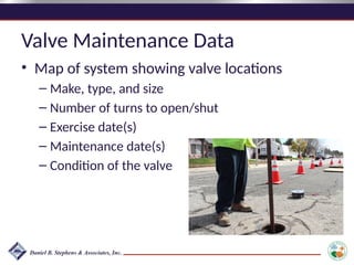
Valve Maintenance Data
•Map of system showing valve locations
– Make, type, and size
– Number of turns to open/shut
– Exercise date(s)
– Maintenance date(s)
– Condition of the valve
47.
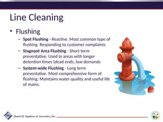
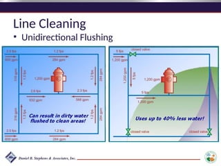
Line Cleaning
• Flushing
–Spot Flushing - Reactive. Most common type of
flushing. Responding to customer complaints
– Stagnant Area Flushing - Short term
preventative. Used in areas with longer
detention times (dead ends, low demands
– System-wide Flushing - Long term
preventative. Most comprehensive form of
flushing. Maintains water quality and useful life
of mains.
48.
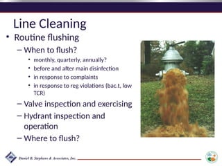
Line Cleaning
• Routineflushing
– When to flush?
• monthly, quarterly, annually?
• before and after main disinfection
• in response to complaints
• in response to reg violations (bac.t, low
TCR)
– Valve inspection and exercising
– Hydrant inspection and
operation
– Where to flush?
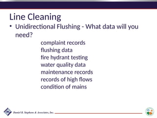
Line Cleaning
• UnidirectionalFlushing - What data will you
need?
complaint records
flushing data
fire hydrant testing
water quality data
maintenance records
records of high flows
condition of mains
51.
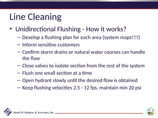
Line Cleaning
• UnidirectionalFlushing - How it works?
– Develop a flushing plan for each area (system maps!!!!)
– Inform sensitive customers
– Confirm storm drains or natural water courses can handle
the flow
– Close valves to isolate section from the rest of the system
– Flush one small section at a time
– Open hydrant slowly until the desired flow is obtained
– Keep flushing velocities 2.5 - 12 fps, maintain min 20 psi
52.
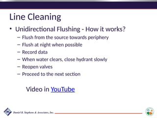
Line Cleaning
• UnidirectionalFlushing - How it works?
– Flush from the source towards periphery
– Flush at night when possible
– Record data
– When water clears, close hydrant slowly
– Reopen valves
– Proceed to the next section
Video in YouTube
53.
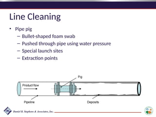
Line Cleaning
• Pipepig
– Bullet-shaped foam swab
– Pushed through pipe using water pressure
– Special launch sites
– Extraction points
54.
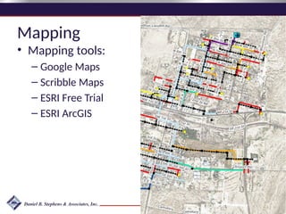
Mapping
• Understanding yoursystem
• Preserving the knowledge
• DSSP, Emergency Response Plan, O&M Plan,
Flushing Program, Asset Management, etc.
• Maps should include:
– locations of all the water system facilities
– pipes (size, material, age, condition)
– valves
– service connections, water meters
Asset Management: AProcess
"Asset management is managing infrastructure
assets to minimize the total cost of owning and
operating them while continuously delivering
the service levels customers desire."
—from the publication Managing Public
Infrastructure Assets
58.
Why do youneed Asset Management?
• Regulatory requirements
– CMOM (Capacity, Management, Operation and
Maintenance Programs for Sanitary Sewer Collection
Systems)
– GASB 34 (Governmental Accounting Standards Board
Station No. 34)
– NMFA (New Mexico Finance Authority)
• Save cost on replacement by extending the life
of assets
• Some funding sources require an AM Plan
59.
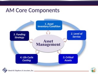
AM Core Components
1.Asset
Inventory/Condition
2. Level of
Service
5. Funding
Strategy
4. Life Cycle
Costing
3. Critical
Assets
Asset
Management
60.
Asset Management Questions
•What assets do we have and where are they?
• What are they worth?
• What is their condition?
• What do we need to do with them?
• When do we need to do it?
• How much will it cost?
• How will we finance it?
61.
Asset Management Benefits
•Increased knowledge of assets, including
which ones are the most critical
• Data-driven decision-making
• Understanding of the relationship between
preventive maintenance and replacement
• Consideration of the capacity of the asset
when deciding to repair or replace
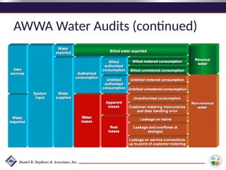
AWWA Water Audits
•M36 Method for conducting water audits:
• Audit looks at:
– Production
– Billing
– Budget
– Data collection
• Based on an audit - where is water lost? (real
vs apparent)
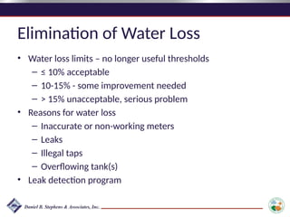
Elimination of WaterLoss
• Water loss limits – no longer useful thresholds
– ≤ 10% acceptable
– 10-15% - some improvement needed
– > 15% unacceptable, serious problem
• Reasons for water loss
– Inaccurate or non-working meters
– Leaks
– Illegal taps
– Overflowing tank(s)
• Leak detection program
66.
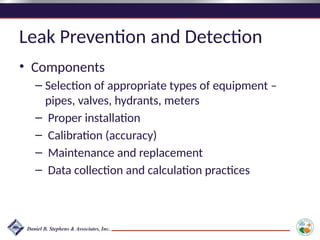
Leak Prevention andDetection
• Components
– Selection of appropriate types of equipment –
pipes, valves, hydrants, meters
– Proper installation
– Calibration (accuracy)
– Maintenance and replacement
– Data collection and calculation practices
67.
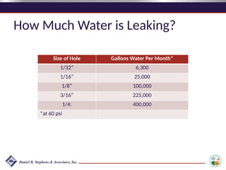
How Much Wateris Leaking?
Size of Hole Gallons Water Per Month*
1/32” 6,300
1/16” 25,000
1/8” 100,000
3/16” 225,000
1/4: 400,000
*at 60 psi
Cross Connections
• Anylink between potable and non-potable
water systems that allow contamination to
enter the potable system
• Contaminants can enter the potable supply
when the pressure in the non-potable system
is greater than the pressure in the potable
system
71.
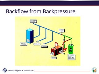
Cross Connections (continued)
•Pressure differential causes 2 types of
backflow – back pressure backflow or back
siphonage backflow
– Back pressure occurs when the non-potable
system has a greater pressure than the potable
system
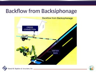
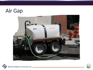
– Back siphonage occurs when there is a vacuum in
the potable system causing non-potable water to
be siphoned into the potable system
72.
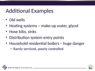
Examples
• Backwash drains– filters, softeners
• Ice, soft drink machines, HVAC, washing
machines
• Chemical feed make-up and carrier water
• Split-feed (pre- and post-chlorination) system
• Water flush for pump bearings
• Fire hydrant drain lines
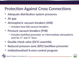
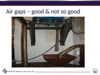
Protection Against CrossConnections
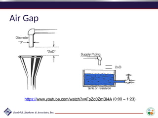
• Adequate distribution system pressures
• Air gap
• Atmospheric vacuum breakers (AVB)
– Includes hose bib vacuum breakers
• Pressure vacuum breakers (PVB)
– Includes backflow preventer w/ intermediate atmospheric
vent for ½” and ¾” lines
• Double check valve (DCV) assembly
• Reduced pressure zone (RPZ) backflow preventer
• Institutionalized X-conn control program
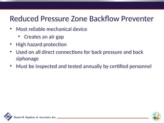
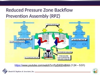
Reduced Pressure ZoneBackflow Preventer
• Most reliable mechanical device
• Creates an air gap
• High hazard protection
• Used on all direct connections for back pressure and back
siphonage
• Must be inspected and tested annually by certified personnel
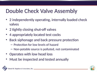
Double Check ValveAssembly
• 2 independently operating, internally loaded check
valves
• 2 tightly closing shut-off valves
• 4 appropriately located test cocks
• Back siphonage and back pressure protection
– Protection for low levels of hazard
– Non-potable source is polluted, not contaminated
• Operates with low head loss
• Must be inspected and tested annually
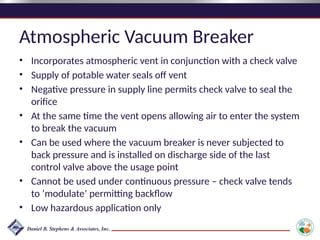
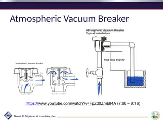
Atmospheric Vacuum Breaker
•Incorporates atmospheric vent in conjunction with a check valve
• Supply of potable water seals off vent
• Negative pressure in supply line permits check valve to seal the
orifice
• At the same time the vent opens allowing air to enter the system
to break the vacuum
• Can be used where the vacuum breaker is never subjected to
back pressure and is installed on discharge side of the last
control valve above the usage point
• Cannot be used under continuous pressure – check valve tends
to ‘modulate’ permitting backflow
• Low hazardous application only
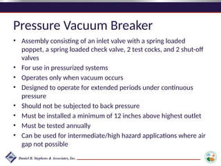
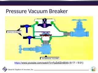
Pressure Vacuum Breaker
•Assembly consisting of an inlet valve with a spring loaded
poppet, a spring loaded check valve, 2 test cocks, and 2 shut-off
valves
• For use in pressurized systems
• Operates only when vacuum occurs
• Designed to operate for extended periods under continuous
pressure
• Should not be subjected to back pressure
• Must be installed a minimum of 12 inches above highest outlet
• Must be tested annually
• Can be used for intermediate/high hazard applications where air
gap not possible
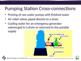
Pumping Station Cross-connections
•Priming of raw water pumps with finished water
• Air relief valves piped directly to a drain
• Cooling water for an emergency generator
submerged in a drain or returned to the potable
supply
GATE VALVE
FLOOR DRAIN
AIR VACUUM RELEASE
SILENT CHECK
#2 6 hour training, 6 credits, an hour for lunch
Group activity – What distribution system issues are you aware of that may have impacted public health? Write down issues and group them together. Groups report out on the 3 most common issues.
#6 Comes in 1/8 to 36 inches, 21ft lenghts
Upper (Vitaulic) lower (Dresser)
#7 Asbestos = Transite (commercial name)
3-36 inches, 13 ft lengths + short sections
Use CI fittings and valves, not made anymore.
Plastic: Both PVC and HDPE have the same OD as CI, PVC can be used to repair CI.
PVC- Bell and spigot joints (lubricate and push in), 1/2 - 16 inch, 20 ft lengths
HDPE - heat fused, stainless steel insert, stainless steel adapters for vitaulic, flanged. up to 3 inch in a roll, larger sizes (up to 16 in) 20 and 40 ft lengths.
HDPE is pressure rated up to 220 psi
#15 This is why fire hydrants have to be on a minimum 6-inch pipe.
#18 A thrust block prevents separation of joints and pipe movement by transferring the resultant thrust force at a bend to the undisturbed soil behind the thrust block. The bearing strength of the soil is expressed in pounds per square foot. Therefore, the area behind the thrust block must engage enough soil area to resist the resultant thrust force at a change in direction.
#21 Address other potential sources of contamination & how the sanitary survey is used to id these
Mention how urbanization can effect separation distances
#23 Gate - most common. Throttling will damage the valve face
#24 Check - when the flow of water should be in one direction only. Footvalves - used in the bottom of the piping to prevent loss of prime.
#27 Never use main valve of dry barrel to throttle flow – anytime main valve not completely open drain hole will open & jetting water from drain hole can undermine soil in vicinity of hydrant
#28 Never use main valve of dry barrel to throttle flow – anytime main valve not completely open drain hole will open & jetting water from drain hole can undermine soil in vicinity of hydrant
#29 International fire code - 3000gpm for 3 hours for non-residential - that means 540,000 of storage.
#33 PD service meter similar to chem feed PD meter
#36 Compound meters need to be serviced and checked that both high and low are registering.
#39 We’ll talk about leak detection in the afternoon.
#40 health and safety- isolation valve LOTO, shoring practices and ladder placement. Have a sump hole
maintenance - wrap around if there’s a puncture hole, cut out and install new pipe with couplings of cracks along the length, flush the line to remove foreign matter
backfill with appropriate materials
refill the line SLOWLY, velocity below 1 fps.
disinfect and take bac-T
#41 Mention glass recycling and crushing to make sand - ideal for backfill material
#43 If can’t keep line isolated while waiting for Bac-T results, can flush with water that has a 0.5 – 1.0 mg/L free chlorine residual
Collect Bac-T sample(s)
Maintain this residual in line until negative sample results are obtained
Then operate line as usual with rest of distribution system
#46 We’ll look at mapping more closely in the later section.
#48 Where? Entire system, or just problematic areas (dead ends, complaint areas, poor quality water etc.)
#49 Conventional Flushing - water from all directions, low velocities, less scouring, don’t control flushing direction
Unidirectional Flushing - water is channeled, higher velocities, better cleaning, systematic, valve operation.
#50 WQ data - records of color, odor, turbidity, bac.t. chlorine residual, DO, pH, temperature. Collect samples during flushing
Maintenance records - valve/main replacements, relining mains, valve inspections etc.
High Flows - main breaks, fires..
#51 Sensitive customers - hospitals, other medical facilities (i.e. dialysis), food processing, specialized manufacturing that uses ultrapure water.
Low velocities for discolored water, higher velocities for sediment removal
#54 There’s a variety of things you can map, for example, pressures, WQ data, leaks, breaks, customer complaints.
#55 What kind of maps do you have? With what info?
ArcGIS Online too is $42/mo. charged annually
Pull up Google Maps
#57 If I have $1 to spend, where should I spend it?
It’s using good data to make decisions.
#58 Some examples of regulations that have prompted the development of Asset Management programs include:
CMOM - capacity, management, operation and maintenance (CMOM) programs for municipal sanitary sewer collection systems.
GASB 34 Governmental Accounting Standards Board 34 addresses how utilities report their assets and the value of those assets.
In NM, The NM Finance Authority has recently taken a position that Asset Management will be required for funding of utility projects.
#59 Let’s use a Groundwater well as an example.
This diagram illustrates the 5 core components of asset management.
Current condition - Prepare an inventory and determine what each well’s condition is. What is its value and useful life? This should include an assessment of current well performance and water quality. These data may then be compared with earlier measurements to see if there has been any deterioration.
What is the required level of service? Is there adequate redundancy in the system to allow a well to fail? Or how long could it be out of service? For a water utility the required level of service generally means being able to provide water 100% of the time.
Which assets are critical? - Based on its age and condition, how likely is a particular well to fail? And then what would be the consequences of failure? They would likely include repair or replacement costs and possibly other impacts such as a reduced level of service, loss of public confidence, or lost revenue.
Minimize life cycle costs - Perform cost-benefit analysis and evaluate how replacement costs compare with maintenance and rehabilitation costs. For example, is it cheaper over the long run to simply run a well to failure and then replace it? Or will periodic maintenance and rehabilitation increase the useful life enough to offset these recurring costs? This assessment needs to consider actual operating costs that can be impacted by deteriorating well performance over time.
Develop funding plan - to cover maintenance, repair and replacement costs taking into account level of service requirements and escalated cash flow and cost estimates.
The circle indicates that this is an ongoing process that requires periodic reevaluation.
#66 Before you spend money on expensive leak detection program, make sure your data is good.
#74 In this example a boiler has its own loop, separated from the potable water system by a check valve. The boiler system adds a scale inhibitor. If the pressure of the boiler system becomes greater than the pressure on the potable water side of the check valve and the check valve fails, then the water will flow back into the potable water supply from the greater pressure in the boiler loop. A check valve is not an adequate barrier for a toxic scale inhibitor. There should be an air gap or RPZ device here.
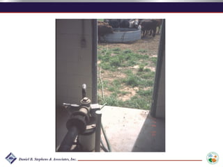
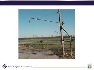
#75 The other type of cross connection is backsiphonage. It occurs when the pressure in the pws drops and siphons unknown quality water into it. In this case a backhoe has broken the pws water main causing the pressure to drop. A hose in a farm truck is submerged in a solution tank. The solution is siphoned through the hose to the water main under negative pressure. We are aware of this type of cross connection happening recently (last 10 years) in Louisiana. Before that it also happened in Oklahoma and Texas in our Region. In the case in Texas some people died. In the Louisiana case a law suit followed and the water system had serious liability problems. The Oklahoma situation ended better, the system had to be flushed for a prolonged period of time but no one became ill.
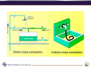
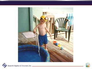
#76 A direct cross connection is one that is permanently plumbed into a system. An indirect cross connection is one that may be temporary like a hose lying below the lip of a sink. I have heard of garden hoses referred to as portable cross connections.
These are common cross connections that you see in water plants. The chemical mixing tank cross connection seems to exist at every small plant in our region. Hoses in sinks are also very common.
#78 The best cross connection protection device is an air gap. It never fails if it is arranged at a 2D distance.
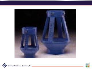
#79 This type of device can be used to assure an airgap is in place at the end of a watering station.
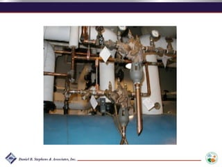
#81 An RPZ is the only mechanical device that is suitable for high hazard situations ( An air gap is still better). It incorporates two check valves and a vacuum breaker in between them. There are test ports for testing each of the three elements. These have to be installed right side up so the vacuum breaker will work. Whenever the system is pressured up it should spit out the vacuum breaker momentarily (until it closes) and then stop. if it flows continually out the middle port, the vacuum breaker is not functioning and at least one of the check valves is not functioning
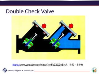
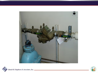
#83 This is a double check valve. This graphic shows the water on the right unable to backflow against the first check valve. If the first on fails there is a back up. Because check valves can stick, they are only suitable for low hazard situations.
#84 An atmospheric vacuum breaker is ok in Non health related situations. It will prevent back siphonage but not backflow. It must be put in vertically so gravity will cause it to close under siphonage conditions. These are subject to failure if they get dirty and stick open.
#85 An atmospheric vacuum breaker is ok in Non health related situations. It will prevent back siphonage but not backflow. It must be put in vertically so gravity will cause it to close under siphonage conditions. These are subject to failure if they get dirty and stick open.
#87 This device incorporates a check valve and an atmospheric vacuum breaker. A check valve will prevent back flow. It is also subject to sticking open however. If you have a device like this it should prevent back flow and back siphonage if it is working properly. The test port make it possible to check its effectiveness. It would be appropriate for intermediate hazard conditions.
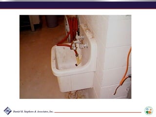
#90 This is a potable water line attached to a hose that is submerged in a floor drain.
#91 This is a potable water line attached to a hose that is submerged in a floor drain.
#92 At pumping stations also there are cross connections that can occur.
As we said earlier, when a pump comes on the air release valve usually spits water and air for a second or two. At some water plants the operators will unknowingly plumb the air relief discharges into a sewer or drain to avoid getting the water on the floor.
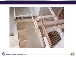
#93 This is an example of an air release valve plumbed directly into a drain. In this case it was a clear well and the hole opened a conduit into the clear well from above.
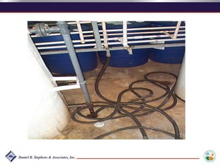
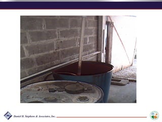
#94 This is a submerged make up water inlet in a barrel that is used to add permanganate to a PWS. Again not a serious health threat but it could screw up some of the chemistry.
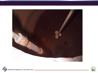
#95 This is a close up of the last photo showing the submerged inlet.
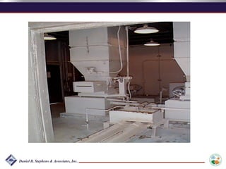
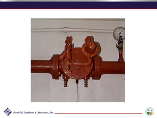
#96 This is a submerged inlet on a lime slurry feeder. The line to the left is a potable water line with a check valve on it. That check valve is the only protection against backflow in this line. It is not a proper device for this type of chemical. As you can see in the mixing chamber the potable water outlet is submerged.
#97 This is a close up of the same feeder. The check valve is behind the mixer. The inlet is obviously submerged.
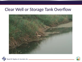
#98 This is actually an overflow from a clear well in a stream but often you will see hoses hooked up to fire hydrants or other orifices that are submerged in streams so the blow off does not flood a neighborhood.
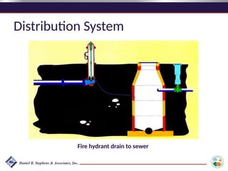
#99 Fire hydrants must drain after they are used and usually they have weep holes around their base. If the weep holes are plumbed directly into a sanitary sewer it can be a problem.
#102 This is the top of the same watering station where we can a the hose end. There is no devise that would guarantee the air gap.
#105 As you can see there is a steady stream in this one so the device is failing.


![Fluid_level_measurement_[2305843009284379220][1].ppt](https://cdn.slidesharecdn.com/ss_thumbnails/fluidlevelmeasurement23058430092843792201-250908081253-b0686685-thumbnail.jpg?width=640&height=640&fit=bounds)


