Call for Papers - Educational Administration: Theory and Practice, E-ISSN: 21...
P&b m6
1. PROBLEMS:
An anchored sheet pile wall of total height 15m is penetrated 4.5 m into a
sandy stratum. It retains a similar sandy soil on its back upto its top with a
horizontal ground surface. The tie bars are horizontal and are provided at a
depth of 2 m below the top. The free water level stands at a height of 8 m above
the dredge line on both sides of the wall. The bulk density of sand above the
free water level is 1.60 3
t/m and the submerged density below the water level is
1 3
t/m . The angle of internal friction of sand is 35˚. Determine the factor of
safety with respect to passive resistance of soil for the given depth of
penetration. What is the anchor pull per metre length of the wall?
1. A gravity wall with a 6 m high vertical back has to retain a cohesionless
backfill with horizontal ground surface. The bulk density of the backfill is
1.60 3
t/m and the angle of shearing resistance is 30˚. The wall is to be 1.4 m
wide at the top. Determine the minimum base width of the wall for no
tension to develop at the base. Also find the factor of safety against sliding
assuming the angle of friction between the base of the wall and the
foundation soil as 30˚. The active pressure may be calculated by the Rankine
theory. The density of the wall is 2 3
t/m .
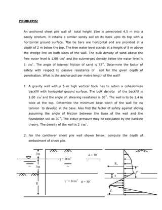
2. For the cantilever sheet pile wall shown below, compute the depth of
embedment of sheet pile.
3m
3m
D
φ = 30˚
γ = 2t/m3
γ ′ = 1t/m3
φ = 30˚
Ra
y′
a
Z
2. 3. In the problem given above, if the soil below the dredge line is cohesive, with
uc = 7.5 3
t/m , uφ = 0˚ and γ ′ = 1.0 3
t/m , compute the depth of embedment
of sheet pile.
4. A 10 m depth and 8 m wide vertical cut is to be made in the subsoil given in
the figure. Compute and comment on the following with respect to the design
of a stable bracing system. a) Factory of safety against bottom heave,
(assume cN =7);
b) Factor of safety against clay bursting;
c) Maximum ground movement and the extent of movement;
d) Axial loads for which the struts are to be designed by considering
apparent earth pressure distribution;
e) Maximum bending moment on the inbuilt wale;
f) Maximum bending moment on the diaphragm wall;
g) Number of pumps required for dewatering purpose during
construction.
Assume 6
soilk 10−
= = 10-6
cm/sec and capacity of each pump = 36
m10−
/se and
an unconfined aquifer condition.
3m
3m
D
φ = 30˚
γ = 2t/m3
γ ′ = 1t/m3 c = 7.5 t/m2
γ ′ = 1t/m3
φ = 30˚
a
e
b
d
3. 2m
3m
3m
4m
Firm clay
c = 40kN/m2
Soft clay
c = 25kN/m2
γ = 18kN/m3
Stiff clay
c = 60kN/m2
Sand
N > 40
- 3m
- 13m
- 16m
h
2m
SOLUTIONS:
7.3/1,27.0
'sin1
'sin1
,35' ===
+
−
=°= apa
KKK
φ
φ
φ
The pressure distribution on the wall is shown in the following figure. The pressures
are calculated for 1m length of the wall:
p1 = 0.27x1.6x2.5 = 1.08 2
t/m .
p2 = 0.27x1.0x12.5 =3.375 2
t/m .
4. 1P = 0.5x1.08x2.5 = 1.35 t acting at 12.5+2.5/3 = 13.33m from B.
2P = 1.08x12.5 = 13.5 t acting at 12.5/2 = 6.25m from B.
3P = 0.5x3.375x12.5 = 21.09 t acting at 12.5/3 = 4.17m from B.
The mobilised passive pressure pmP acts at a height of 1.5m from B. Taking
moments about E, the level of tie bars, we get pmP = 24.08 t.
Ultimate passive resistance Pp of soil is given by:
pP = ½ pK γ ′x 2
4.5 = 37.46 t.
Therefore Factor of safety F = pP / pmP = 1.56
Total active pressure aP = 35.94 t
Anchor pull TR = pP - pmP = 11.86 t per metre length of the wall.
2. When φ ′ = 30˚, aK = 1/3
Consider 1m length of the wall. Total active pressure
2
a a
1
P K H 9.6t
2
γ= =
E
P2
RT
P1
p1
P3
p2
Pp
2.5m
8m
4.5m
1.5m
2m
B
A
5. aP acts horizontally at a height of 2m from the heel.
For no tension to develop at the base, the resultant of aP and the weight of wall
intersects the base at a distance of 2b/3 from the heel. For taking moments the
section of the wall may be divided into a rectangle of height 6m and width 1.4m
(top width) and a triangle of height 6m and base width (b – 1.4) metres. The
moments of the forces are taken about the heel.
From the moment equation we get, b = 2.77m
Total weight W of the wall per metre length = 1.4 x 2.77 x 6 x 2 / 2 = 23.27 t
The factor of safety F against sliding is given as follows:
39.1
6.9
30tan27.23'tan
=
°
==
a
P
W
F
δ
3. Here, φ = 30˚
3/1
sin1
sin1
=
+
−
=
φ
φ
A
K and
3
sin1
sin1
=
−
+
=
φ
φ
P
K
Earth pressure at the dredge line,
AeP = (2 x 3 + 1x 3)1/3 = 3 2
t/m
The distance of point of zero pressure below dredge line is given by
( )
m
KK
P
a
AP
Ae
125.1
'
=
−
=
γ
Resultant of all the forces above point O,
aR = 12.19 t/m
Taking the moment of all the forces about point O
y ′ = 2.92m
6. Passive earth pressure at point O
poP = 30 2
t/m
If the depth of penetration of sheet pile below O is Y, pressure at the base of
the wall is given by :
pb2P = 1(3-1/3)Y = 2.67Y
pb1P = 30 + 2.67Y
Substituting the values aR = 12.19 2
t/m , y ′ = 2.92m, pb2P = 2.67Y and pb1P = 30 +
2.67Y in the following equations,
pb2 a
pb1 pb2
p Y-2R
Z=
p +p
6 aR (Y+y′) + Z2
( pb2P + pb1P ) – pb2P 2
Y = 0
we get,
4
Y + 13.48 3
Y + 89.71 2
Y – 467.69Y – 981.97 = 0
The solution of the equation by trial and error yields, Y = 4.24m
With Y = 4.24m,
pb2P = 11.32 2
t/m
pb1P = 41.32 2
t/m
Hence we get, Z = 0.45m
Check: Σ ΣFH = 0; aR + ( pb2P + ppb1)Z/2 - pb2P Y/2 = 0
or 12.19 + (11.32 + 41.32) x 0.45/2 – 11.32 x 4.24/2 ≈ 0.
Hence in order.
Depth of pile penetration, D = a + Y = 1.125 + 4.24 = 5.37m
Increase D by 30 percent and adopt depth of pile penetration as 5.37 x 1.30 =
6.98m.
7. 4. Effective stress at the dredge line,
q′ = 2 x 3 + 1 x 3 = 9 2
t/m
The earth pressure diagram is shown in the figure.
The resultant of all the forces above the dredge line, Ra = 12.19 v acts at a height
y′ above the dredge line y′ = 1.86m
Substituting in the eqn. ( )
( )
0
'2
'12
2'42
=
+
+
−−−
qc
RycR
DRqcD
u
aua
au
2
D – 1.16D – 4.34 = 0
Hence we get, D = 2.74m
Check: ∑ = 0
Depth of embedment provided = 2.74 x 1.30 = 3.56m.
. From stability considerations :
a) Bottom heave:
H = 10m , γ = 18kN/ 3
m , c = 25kN/ 4
m , 1D = minimum of B/ 2 or D = 8 2
or 2 i.e. 1D = 2.
2t/m2
12.19t/m
2
y′=1.86m
3t/m2
Z
8. Therefore, Stability No. = γ H/c = 7.2 >6 . hence the diaphragm wall is required.
+
++
=
∑
f
DH
D
cH
f
D
c
cN
FOS
γ
γ
1
= 2.81 > 2, hence it is safe against bottom heave.
b) Clay bursting :
h
B
cH
H
FOS
w
γ
γ 1
1
2+
= = 1.32 > 1.3, therefore, it is safe against clay bursting.
c)
From Peck’s chart we find that the present situation lies in the zone II.
Maximum ground movement:
Hence maximum ground movement δ = 2x10/100 = 0.2 m = 200 mm.
And the maximum extent of ground movement L = 3x10 = 30 m.
d)
From structural considerations:
Strut loads;
9. Soft clay
−=
H
c
mHpa
γ
γ
4
1 , N = γH/c = 7.2 > 4, ∴m = 1.
∴ ap = 80kN/ 2
m .
Hence for struts @ 3m c/c, the following are the strut loads:
1P = 540kN , 2P = 720kN, 3P = 600kN.
e)
mkNm
Pl
M /72
10
2
max
==
Maximum bending moment of the diaphragm wall:
f)
Span of the inbuilt wales l = 3m c/c.
Moment in inbuilt wale:
Ud1 w = 80kN/ 2
m .
mkNm
wl
M /90
8
2
max
==∴ .
g)
Discharge per well, Q;
Dewatering criteria:
2m
3m
3m
2m
P1
P2
P3
2.5m
7.5m
p
a
10. ( )
( )rR
hHk
Q
/log3.2
22
−
=
π
where, k = 6
10−
cm/sec.
H = 16 – 3 = 13m.
h = 16 – 10 = 6m.
r = 4m.
R = 10r = 40m.
∴Q = 1.82 x 6
10− 3
m /sec.
Hence the number of pumps required = 1.82 x 6
10−
/ 6
10−
= 1.82 ≈2.