New from BookNet Canada for 2024: BNC BiblioShare - Tech Forum 2024
SDH/STM-1 Trunk Card Configuration Guide
1. C H A P T E R
4
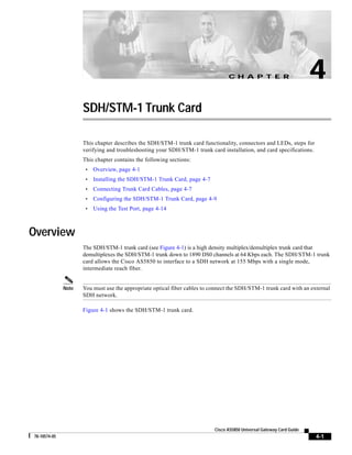
SDH/STM-1 Trunk Card
This chapter describes the SDH/STM-1 trunk card functionality, connectors and LEDs, steps for
verifying and troubleshooting your SDH/STM-1 trunk card installation, and card specifications.
This chapter contains the following sections:
•
Overview, page 4-1
•
Installing the SDH/STM-1 Trunk Card, page 4-7
•
Connecting Trunk Card Cables, page 4-7
•
Configuring the SDH/STM-1 Trunk Card, page 4-9
•
Using the Test Port, page 4-14
Overview
The SDH/STM-1 trunk card (see Figure 4-1) is a high density multiplex/demultiplex trunk card that
demultiplexes the SDH/STM-1 trunk down to 1890 DS0 channels at 64 Kbps each. The SDH/STM-1 trunk
card allows the Cisco AS5850 to interface to a SDH network at 155 Mbps with a single mode,
intermediate reach fiber.
Note
You must use the appropriate optical fiber cables to connect the SDH/STM-1 trunk card with an external
SDH network.
Figure 4-1 shows the SDH/STM-1 trunk card.
Cisco AS5850 Universal Gateway Card Guide
78-10574-05
4-1
2. Chapter 4
SDH/STM-1 Trunk Card
Overview
Figure 4-1
SDH/STM-1 Trunk Card
Backplane
connector
SDRAM
-1
STM
OC3/
HERE
72152
CODE
BAR
T
AIN
/M
RT
ST
PO
T
AC
OK
TE
T1
OR
P
RM
ALA
3
W/P
2
BLE
0 NA
E
RT
PO
RM
LE
AB
EN
W/P
ALA
Features
•
Line termination
– Up to 63 E1s mapped as TU12
•
De-multiplexes calls
The SDH/STM-1 trunk card is a high density multiplex/demultiplex card that takes in an STM-1 (SDH)
pipe, used to transport up to 1890 DS0 (30 DS0 per E1) channels in ISDN PRI and E1 R2 configuration
and 1953 DS0 (31 DS0 per E1) in SS7 with A-link configuration. In case of NFAS or F-link
configuration, between 1890 DS0 to 1953 DS0 channels can be transported. In one direction, a framer
removes framing and embedded signaling bits, and the CPU sends the data stream to onboard
time-division multiplexing (TDM) resources, which break out each call (DS0) and pass each call to
an appropriate call termination resource. Digital calls are terminated onboard the SDH/STM-1 trunk
card on HDLC controllers. There are 512 HDLC controllers and each HDLC controller can be used
for either a D-channel or one digital call. The SDH/STM-1 trunk card can terminate a maximum of
512 digital calls, less the number of D-channels. For example, with 63 D-channels allocated, 449
digital calls can be terminated. Additional digital calls and analog modem-originated calls are
passed over the TDM bus to an available modem resource. The system software controls port and
HDLC resource management. In the other direction, the process is reversed.
•
Supports online insertion and removal (OIR)
The SDH/STM-1 trunk card supports OIR, a feature that allows you to remove and replace trunk
cards in the Cisco AS5850 while the system is operating, without disrupting other cards and their
associated calls. If you remove a trunk card while the system is operating, all calls associated with
the lines on that card are dropped. Calls being handled by other trunk or modem cards, however, are
not affected. For more information, see the “Busyout Command” section on page 1-1.
Cisco AS5850 Universal Gateway Card Guide
4-2
78-10574-05
3. Chapter 4
SDH/STM-1 Trunk Card
Overview
•
Testing
– Drop and insert testing on a test DS1/E1 from an external testing device
– Monitors both transmit and receive directions on any E1s with a built-in DS1/E1 interface
•
SFF optical SMF LC transceiver
•
Core processor: Motorola 8260 PowerQuicc II with 32 MB of SDRAM and 512 KB flash ROM on
board.
•
F-link support
– Terminates SS7 F-links and forwards the signaling channels to a call agent through another
TDM trunk.
The Cisco AS5850 supports T1, E1, and T3 trunk cards. Table 4-1 shows the possible trunk card
configurations:
Table 4-1
Maximum Number of Trunk Cards
First RSC
Second
RSC
Total Trunk Cards
per Chassis
Total 324-Port
UPC
Total
Total
TrunkD DS0
S0s
Ports
24T1 only
2 24T1
2 24T1
4
8
2304
2592
T3 only
2 T3
2 T3
4
6
2688
2808
24T1/T3
combination
2 24T1
2 T3
4
7
2496
2700
24T1/T3
combination
1 24T1,
1 T3
1 24T1,
1 T3
4
8
2496
3024
24T1/T3
combination
1 24T1,
1 T3
2 T3
4
7
2592
2916
24T1/T3
combination
2 24T1
1 24T1,
1 T3
4
8
2400
2808
24E1 only
2 24E1
2 24E1
4
8
2880
2592
STM1 only
1STM1
1 STM1
2
10
4032
3240
24E1/STM1
combination
2 24E1
1 STM1
3
9
3456
2916
Chassis Trunk
Type
Note
Mixing CT1 or CT3 and CTE1 trunk cards in the same chassis is not supported. If this configuration
guideline is violated, an error message appears on the RSC, and the disallowed card is shut down.
Interface Specifications
The physical layer interface for the SDH/STM-1 trunk card is synchronous transport module (STM).
Each SDH/STM-1 trunk card has two 155.52-Mbps STM physical layer interfaces, but only one interface
will be used. Each SDH/STM-1 trunk card has two LC small form-factor type fiber receptacles to allow
connection to single-mode optical fiber. Table 4-2 describes the SDH/STM-1 trunk card optical
specifications.
Cisco AS5850 Universal Gateway Card Guide
78-10574-05
4-3
4. Chapter 4
SDH/STM-1 Trunk Card
Overview
The SDH/STM-1 trunk card supports SDH MIB RFC 1595 and DS1 MIB RFC 1406, and provides support
for SNMP agent v1 (RFC 1155-1157), and Management Information Base (MIB) II (RFC 1213).
Note
Table 4-2
Support for SDH MIB RFC 1595 includes sonetMedium, sonetSection, sonetLine, sonetPath, and
sonetVT groups and not sonetFarEndLine, sonetFarEndPath, and sonetFarEndVT groups.
SDH/STM-1 Trunk Card Optical Specifications
Fiber Type
Connector Type
Operating
Wavelength
Transmit Power
Receive Sensitivity Minimum Distance
Single-mode
intermediate-reach
LC duplex
1261–1360 nm
–8 dBm (max)
–7 dBm (max)
–15 dBm (min)
–28 dBm (min)
9.3 miles (15 km)
1
1. bit error rate (BER) = 1*10–10
SONET and SDH Overview
SONET is an American National Standards Institute (ANSI) standard (T1.1051988) for optical digital
transmission at hierarchical rates from 51.840 Mbps (STS-1) to 2.488 Gbps (STS-48) and higher. SDH
is the international standard for optical digital transmission at hierarchical rates from 155.520 Mbps
(STM-1) to 2.488 Gbps (STM-16) and higher.
Both SONET and SDH are based on a structure that has a basic frame and speed. The frame format used
by SONET is the synchronous transport signal (STS), with STS-1 being the base level signal at
51.84 Mbps. An STS-1 frame can be carried in an OC-1 signal. The frame format used by SDH is the
synchronous transport module (STM), with STM-1 being the base level signal at 155.52 Mbps. An
STM-1 frame supports the same payload capacity as an OC-3 signal. The payload of an STM-1 frame
can be carried in an OC-3 signal with suitable SDH-to-SONET translation.
Both SONET and SDH have a hierarchy of signaling speeds. Multiple lower-level signals can be
multiplexed together to form higher-level signals. For example, three STS-1 signals can be multiplexed
together to form an STS-3 signal, and four STM-1 signals multiplexed together form an STM-4 signal.
The International Telecommunications Union Telecommunication Sector (ITU-T) defines a series of
SDH transmission rates beginning at 155.520 Mbps. (See Table 4-3.)
Table 4-3
SDH Transmission Rates
SONET 11
SDH Equivalent
STS-3(c)
STM-12
STS-12(c)
STM-4(c)
STS-48(c)
STM-16(c)
1. ANSI-defined SONET specifications
2. Currently supported by the SDH/STM-1 trunk card
Cisco AS5850 Universal Gateway Card Guide
4-4
78-10574-05
5. Chapter 4
SDH/STM-1 Trunk Card
Overview
Clocking
Each RSC card contains a block of logic referred to as the common logic and system clocks. This block
generates the backplane Stratum-4 compliant 4-MHz and 8-kHz clocks used for interface timing and for
the TDM bus data movement. The common logic can use a variety of sources to generate system timing,
including a T1 or E1 signal, or input from the BNC connector on the RSC front panel. Only one common
logic, on one RSC, is active at a time, identified by the CLK LED on the RSC card front panel. The active
common logic is user-selectable and is independent from each RSC card. This assures that if you need
to replace an RSC, or if the slave RSC becomes the master, clocking remains stable. The selected
common logic should not be changed during normal operation unless a hardware failure is suspected or
diagnosed in the RSC card.
Each RSC card in the Cisco AS5850 may select from 14 total clock inputs generated from any line card
in the chassis or from the RSC front panel BITS input. The default clock source will come from the first
trunk card that boots up. If there are no good clocks available, the RSC generates clock for the system.
Note
If there are two RSCs in the chassis, the RSC that boots first will assign the primary clock source.
By using the clock source command and the dial-tdm-clock command the user can select and prioritize
the clocking source that will be used by the system.
Note
Loop, line and external timings are supported on the STM-1 card.
For more information about these clocking commands, refer to Cisco IOS Dial Technologies Command
Reference and Cisco IOS Interface Command Reference. You can access these documents at: Cisco
Product Documentation > Cisco IOS version you are using > Configuration Guides and Command
References.
LED Indicators
The SDH/STM-1 trunk card front panels are designed with LED indicators (Figure 4-2) to provide trunk
card status and port-level monitoring information.
Cisco AS5850 Universal Gateway Card Guide
78-10574-05
4-5
6. Chapter 4
SDH/STM-1 Trunk Card
Overview
Figure 4-2
SDH/STM-1 Trunk Card LEDs
PORT 0
ENABLE TX RX
ALARM LED
ENABLE
W/P ALARM
ENABLE LED
W/P LED
TX
PORT 0
W/P ALARM
PORT 1
TX RX
RX
TX
PORT 1
RX
TEST PORT
TEST PORT
ACT OK/MAINT
72153
ACT LED
OK/MAINT LED
The two types of LEDs for the SDH/STM-1 trunk cards are:
•
Card-level LEDs, which provide status information for card maintenance
•
Port-associated LEDs, which provide warning signals and configuration status for individual
connections
All LEDs are visible from the front panel.
Table 4-4 lists the LEDs and their functions.
Table 4-4
SDH/STM-1 Trunk Card LED Description
LED
Color
Description
ENABLE
Green
Port enabled and laser on.
Off
The port is not enabled.
W/P
Off
Not implemented at this time.
ALARM
Yellow
Port is in an alarm condition.
Note
ACT
ALARM LED turns yellow at LOS or LOF and MS-RDI
alarms in AU-4 or AU-3 mapping, and it also turns yellow
at AU-LOP, AU-AIS, or HP-UNEQ alarms in AU-4
mapping.
Ok
Yellow
There is a subsystem failure on the card.
Red
The card has failed to come up.
Green
There is power to the card.
Yellow
OK/MAINT
Green
There is a subsystem failure on the card.
Cisco AS5850 Universal Gateway Card Guide
4-6
78-10574-05
7. Chapter 4
SDH/STM-1 Trunk Card
Installing the SDH/STM-1 Trunk Card
Table 4-5
SDH/STM-1 Trunk Card LED States
ENABLE
W/P1
ALM
State
ON
—
OFF
Port up (Active), laser on, working port
ON
—
ON
Port up, port in alarm
OFF
—
OFF
Port inactive
1. The W/P LED is not implemented at this time.
Specifications
Table 4-6 lists the SDH/STM-1 trunk card specifications.
Table 4-6
SDH/STM-1 Trunk Card Specifications
Description
Specification
Dimensions H x W x L
15.5 x 1.23 x 19 in. (39.37 x 3.12 x 48.26 cm)
Weight
8 lb (3.6 kg)
Transmission bit rate
155.52 Mbps
Power requirements
-48 VDC at 2 A (power consumption: 3.3 VDC and 5 VDC)
Regulatory compliance
and safety1
CFR47 Part 15 (FCC) class B, ICES 003 class B, EN61000-3-2,
EN55022 class B,CISPR22 class B, VCCI Class B
1. See also the regulatory compliance and safety document that shipped with your Cisco AS5850.
Installing the SDH/STM-1 Trunk Card
For instructions about installing and removing cards in the Cisco AS5850, see Chapter 1, “Replacing or
Installing Server Cards.”
Connecting Trunk Card Cables
The SDH/STM-1 trunk card has two SFF-LC, SM optical connectors.
Follow these steps to connect an SDH/STM-1 trunk card to the network:
Warning
Do not work on the system or connect or disconnect cables during periods of lightning activity. To see
translations of the warnings that appear in this publication, refer to the Regulatory Compliance and
Safety Information that accompanied this device.
Step 1
Attach either one duplex optical fiber cable or two simplex optical fiber cables to the optical connector
for port 0. (See Figure 4-3.)
Note
Port 0 is the default “working” port.
Cisco AS5850 Universal Gateway Card Guide
78-10574-05
4-7
8. Chapter 4
SDH/STM-1 Trunk Card
Connecting Trunk Card Cables
Figure 4-3
Connecting the SDH/STM-1 Trunk Card
PORT 0
ENABLE TX RX
TX
PORT 1
TX RX
RX
W/P ALARM
PORT 1
Duplex LC cable
ENABLE
RX
TX
W/P ALARM
PORT 0
TEST PORT
88318
ACT OK/MAINT
Step 2
Attach the other end of the fiber cable to the external SDH network device.
Note
Make sure the transmit on the SDH/STM-1 trunk card goes to the receive on the other end.
Note
For cable specifications, see Appendix A, “Cabling Specifications.”
Verifying and Troubleshooting the Installation
When you first power on your Cisco AS5850 universal gateway, all LEDs go on while the system runs
a series of diagnostics. After the system passes initial diagnostics, all LEDs go off and then go on again.
Table 4-7 provides a quick reference for nominal LED readings for Cisco AS5850 core components. If
LED readings vary from those listed, refer to the Cisco AS5850 Universal Gateway Hardware
Installation Guide for troubleshooting information.
To complete the installation, verify that the SDH/STM-1 trunk card LEDs operate properly by observing
the LED states. (See Table 4-5.)
Table 4-7
Cisco AS5850 Nominal LED Readings
Component
LED
Color/Condition
DC PEMF
POWER
Green/on
MISWIRE
Yellow/off
Cisco AS5850 Universal Gateway Card Guide
4-8
78-10574-05
9. Chapter 4
SDH/STM-1 Trunk Card
Configuring the SDH/STM-1 Trunk Card
Table 4-7
Cisco AS5850 Nominal LED Readings (continued)
Component
LED
Color/Condition
Route switch
controller card
PWR
Green/on
HIST
Yellow/off
MAINT
Yellow/off
ALARM
Yellow/off
MAST
Green/on
CLK
Green/on
FLASH
Green/on
LINK
Green/on
ACT
Green/on
POWER
Green/on
Cooling module
FAULT BANK 1 Yellow/off
FAULT BANK 2 Yellow/off
Configuring the SDH/STM-1 Trunk Card
This section shows how to configure the SDH/STM-1 trunk card. A SONET controller is automatically
created when the SDH/STM-1 trunk card is detected by the system. The basic configuration steps
include:
•
Configure the SONET Controller
•
Configuring Administrative Unit Group (AUG) Mapping under SDH Framing
•
Configuring the E1 controller
Configure the SONET Controller
The following steps will configure the basic SONET controller:
Command
Step 1
Purpose
Gateway> enable
Password: password
Use the enable command and password to enter privileged
EXEC mode. You are in privileged EXEC mode when the
prompt changes to Gateway#.
Gateway#
Step 2
Gateway# configure terminal
Enter configuration commands, one per line.
End with CNTL/Z.
Gateway(config)#
Enter global configuration mode. You are in global
configuration mode when the prompt changes to
Gateway(config)#.
Cisco AS5850 Universal Gateway Card Guide
78-10574-05
4-9
10. Chapter 4
SDH/STM-1 Trunk Card
Configuring the SDH/STM-1 Trunk Card
Command
Step 3
Purpose
Gateway(config)# controller sonet slot/port
Enter controller configuration mode to configure your
controller. You are in controller configuration mode when
the prompt changes to Gateway(config-controller)#.
Gateway(config-controller)#
Note
Note
Step 4
Gateway(config-controller)# main-fiber port {0
| 1}
Gateway(config-controller)#
The SONET controller is automatically created
when the SDH/STM-1 trunk card is detected by the
system.
To configure the “active” port select port “0”.
Optional: Enter the port the optical link is connected to. Port
0 is the default.
Note
If you are changing the optical port, make sure to
remove any existing controller sonet commands for
the existing port: loopback, overhead j0, b2 sd-ber,
b2 sf-ber, and apply those commands to the new
port.
Step 5
Gateway(config-controller)# framing {sdh}
Gateway(config-controller)#
Enter the framing type (optional, defaults to “SDH”).
Step 6
Gateway(config-controller)# clock source
[{internal | line | loop}]
Gateway(config-controller)#
Set the transmit clock source for the SONET controller
(optional, defaults to internal).
Note
The internal clock source is the clock provided by
the RSC.
Note
Line timing: Select the system primary clock from
the optical line and the recovered clock will go
through RSC PLL circuitry. Should be used with one
or more STM1 cards in the system.
Note
Loop Timing: Select the system primary clock from
the optical line and the same recovered clock will be
used in tx direction without going through RSC PLL
circuitry. Should be used with only one STM1 card
in the system.
Step 7
Gateway(config-controller)# overhead j0
[{transmit | receive}] string
Gateway(config-controller)#
Define a string for peer authentication. (optional)
Step 8
Gateway(config-controller)# b2 sf-ber {3-9}
Gateway(config-controller)#
Set signal failure BER threshold, range 10-3 to 10-9
Step 9
Gateway(config-controller)# b2 sd-ber {3-9}
Gateway(config-controller)#
Set signal degrade BER threshold, range 10-3 to 10-9
Step 10
Gateway(config-controller)# description string
Gateway(config-controller)#
Add a description for the controller (optional).
Step 11
Gateway(config-controller)# no shutdown
Gateway(config-controller)#
Enable the controller.
Step 12
Gateway(config-controller)# exit
Gateway(config)#
Return to global configuration mode.
Cisco AS5850 Universal Gateway Card Guide
4-10
78-10574-05
11. Chapter 4
SDH/STM-1 Trunk Card
Configuring the SDH/STM-1 Trunk Card
Command
Step 13
Step 14
Purpose
Gateway(config)# dial-tdm-clock priority
{1-50} [(freerun | external | trunk-slot slot
number)] [line {0-1}]
Gateway(config)#
Set the clock source priority. The lower the number, the
higher the priority. (optional)
Gateway(config)# ctrl-z
Gateway#
Return to privileged EXEC mode.
Note
This command will override the default clocking
algorithm and allows you to specify a specific clock
source. line designates the optical port. If optical
port 0 is selected, 0 should be selected for the line.
Configuring Administrative Unit Group (AUG) Mapping under SDH Framing
In SDH, there are two possible mapping/multiplexing schemes for most payload types: ANSI and ETSI.
The SDH/STM-1 trunk card supports both schemes.
In ANSI mapping, the low order payloads are aggregated into a VC-3 high order path. An AU pointer is
added to the VC-3 to create an AU-3 (Administrative Unit type 3). Three such AU-3s are then
synchronously multiplexed into an AUG (AU group). The multiplexing scheme is as follows:
VC-3 <-> AU-3 (x3) <-> AUG <-> STM-1
In ETSI mapping, the low order payloads are aggregated into a VC-4 high order path. An AU pointer is
added to the VC-4 to create an AU-4 (Administrative Unit type 4). One AU-4 is “multiplexed” into an
AUG (AU group), which is to say, the AUG is, in fact, equivalent to an AU-4. The multiplexing scheme
is as follows:
TUG-3 (x3) <–> VC-4 <–> AU-4 (x1) <–> STM-1
Configuring a TUG-3 under AU-4 AUG Mapping
Under SDH framing with AUG mapping set to AU-4, the VC-4 high order path comprises three TUG-3s.
Each TUG-3 can be configured to carry up to 21 E1s, mapped into VC-12s. The mode of operation of a
TUG-3 is not configurable, and defaults to mode c-12.
When you are configuring theSDH/STM-1 trunk card for SDH framing, and have selected au-4 as the
mode of operation, you can configure a TUG-3 using the following steps:
Command
Step 1
Purpose
Router(config)# controller sonet slot/port
Select the SONET controller you want to configure.
Router(config-controller)#
Step 2
Router(config-controller)# aug mapping
[{au-4 | au-3}]
Select AUG mapping. (optional, defaults to “au-4”).
Router(config-controller)#
Step 3
Router(config-controller)# au-4 1 tug-3
number
Router(config-controller-tug3)#
For au-4, specify the au-4 number and enter TUG-3
configuration mode.
or
Router(config-controller)# au-3 number
Router(config-controller-au3)#
For au-3, specify the au-3 number and enter au-3 configuration
mode.
Cisco AS5850 Universal Gateway Card Guide
78-10574-05
4-11
12. Chapter 4
SDH/STM-1 Trunk Card
Configuring the SDH/STM-1 Trunk Card
Command
Purpose
Step 4
Router(config-controller-tug3)# overhead
j1 [{length | 16 | 64} | {receive-message
| transmit-message text}]
Router(config-controller-tug3)#
Configure the message length and the message text of the high
order path trace identifier. The default for SDH framing is 16
(optional).
Step 5
Router(config-controller-tug3)# tug-2
{1-7} e1 {1-3}
Router(config-controller-tug3)#
Create the E1 controllers.
Step 6
Gateway(config-controller-tug3)# ctrl-z
Gateway#
Return to privileged EXEC mode.
Configuring the E1 controller
You can allocate the available channels for channelized E1 in the following ways:
•
All channels can be configured to support ISDN PRI.
•
If you are not running ISDN PRI, all channels can be configured to support robbed-bit signaling
(also known as channel-associated signaling (CAS)).
•
All channels can be configured in a single channel group.
•
Mix and match channels supporting ISDN PRI, channel grouping, and CAS.
Follow these steps to configure an E1 controller:
Command
Step 1
Purpose
Gateway# configure terminal
Enter configuration commands, one per line. End with
CNTL/Z.
Enter global configuration mode. You are in global
configuration mode when the prompt changes to
Gateway(config)#
Step 2
Router(config)# controller E1 slot/port.path/tug-2/E1
Gateway(config)#.
Select the E1 controller you want to configure.
Router(config)#
Note
For information about configuring the individual E1 controllers, refer to Cisco AS5850 Universal
Gateway Commissioning Guidelines and Cisco AS5850 Universal Gateway Operations, Administration,
Maintenance, and Provisioning Guide. You can access these documents at: Cisco Product
Documentation > Access Servers > Cisco AS5850 > Configuration Documents for Cisco AS5850
Note
For ISDN PRI—If you do not specify the time slots, the specified controller is configured for 30 B
channels and1 D channel. B channel numbers range from 1 to 31; channel 16 is the D channel for E1.
Corresponding serial interface numbers range from 0 to 30. In commands, the D channel is interface
serial slot/port.path/tug-2/e1:15—for example, interface serial 3/0.1/1/1:15.
Verify
To verify controller and path status, enter the show controllers sonet command.
Gateway# sh controllers sonet
SONET 3/0 is down.
Cisco AS5850 Universal Gateway Card Guide
4-12
78-10574-05
13. Chapter 4
SDH/STM-1 Trunk Card
Configuring the SDH/STM-1 Trunk Card
Applique type is Channelized Sonet/SDH
Clock Source is Internal, AUG mapping is AU4.
Medium info:
Type: SDH, Line Coding: NRZ, Line Type: Short SM
Regenerator Section Status:
LOS
Multiplex Section Status:
Higher Order Path Status:
Path# 1 has no defects
Lower Order Path Status:
VC-12 1/1/1/1 has no defects
VC-12 1/1/1/2 has no defects
VC-12 1/1/1/3 has no defects
VC-12 1/1/2/1 has no defects
VC-12 1/1/2/2 has no defects
VC-12 1/1/2/3 has no defects
VC-12 1/1/3/1 has no defects
VC-12 1/1/3/2 has no defects
VC-12 1/1/3/3 has no defects
VC-12 1/1/4/1 has no defects
VC-12 1/1/4/2 has no defects
VC-12 1/1/4/3 has no defects
VC-12 1/1/5/1 has no defects
VC-12 1/1/5/2 has no defects
VC-12 1/1/5/3 has no defects
VC-12 1/1/6/1 has no defects
VC-12 1/1/6/2 has no defects
VC-12 1/1/6/3 has no defects
VC-12 1/1/7/1 has no defects
VC-12 1/1/7/2 has no defects
VC-12 1/1/7/3 has no defects
.
.
.
VC-12 1/3/5/3 has no defects
VC-12 1/3/6/1 has no defects
VC-12 1/3/6/2 has no defects
VC-12 1/3/6/3 has no defects
VC-12 1/3/7/1 has no defects
VC-12 1/3/7/2 has no defects
VC-12 1/3/7/3 has no defects
Data in current interval (20 seconds elapsed):
Regenerator Section:
0 CVs, 20 ESs, 20 SESs, 0 SEFSs
Multiplex Section:
0 CVs, 0 ESs, 0 SESs, 0 UASs
Higher Order Path:
Path# 1: 0 CVs, 0 ESs, 0 SESs, 20 UASs
Lower Order Path:
VC-12 1/1/1/1: 0 CVs, 0 ESs, 0 SESs, 20 UASs
VC-12 1/1/1/2: 0 CVs, 0 ESs, 0 SESs, 20 UASs
VC-12 1/1/1/3: 0 CVs, 0 ESs, 0 SESs, 20 UASs
VC-12 1/1/2/1: 0 CVs, 0 ESs, 0 SESs, 20 UASs
VC-12 1/1/2/2: 0 CVs, 0 ESs, 0 SESs, 20 UASs
VC-12 1/1/2/3: 0 CVs, 0 ESs, 0 SESs, 20 UASs
VC-12 1/1/3/1: 0 CVs, 0 ESs, 0 SESs, 20 UASs
VC-12 1/1/3/2: 0 CVs, 0 ESs, 0 SESs, 20 UASs
VC-12 1/1/3/3: 0 CVs, 0 ESs, 0 SESs, 20 UASs
Cisco AS5850 Universal Gateway Card Guide
78-10574-05
4-13
14. Chapter 4
SDH/STM-1 Trunk Card
Using the Test Port
VC-12
VC-12
VC-12
VC-12
VC-12
VC-12
VC-12
VC-12
VC-12
VC-12
VC-12
VC-12
.
.
.
VC-12
VC-12
VC-12
VC-12
VC-12
VC-12
VC-12
Gateway#
1/1/4/1:
1/1/4/2:
1/1/4/3:
1/1/5/1:
1/1/5/2:
1/1/5/3:
1/1/6/1:
1/1/6/2:
1/1/6/3:
1/1/7/1:
1/1/7/2:
1/1/7/3:
0
0
0
0
0
0
0
0
0
0
0
0
CVs,
CVs,
CVs,
CVs,
CVs,
CVs,
CVs,
CVs,
CVs,
CVs,
CVs,
CVs,
0
0
0
0
0
0
0
0
0
0
0
0
ESs,
ESs,
ESs,
ESs,
ESs,
ESs,
ESs,
ESs,
ESs,
ESs,
ESs,
ESs,
0
0
0
0
0
0
0
0
0
0
0
0
SESs,
SESs,
SESs,
SESs,
SESs,
SESs,
SESs,
SESs,
SESs,
SESs,
SESs,
SESs,
20
20
20
20
20
20
20
20
20
20
20
20
UASs
UASs
UASs
UASs
UASs
UASs
UASs
UASs
UASs
UASs
UASs
UASs
1/3/5/3:
1/3/6/1:
1/3/6/2:
1/3/6/3:
1/3/7/1:
1/3/7/2:
1/3/7/3:
0
0
0
0
0
0
0
CVs,
CVs,
CVs,
CVs,
CVs,
CVs,
CVs,
0
0
0
0
0
0
0
ESs,
ESs,
ESs,
ESs,
ESs,
ESs,
ESs,
0
0
0
0
0
0
0
SESs,
SESs,
SESs,
SESs,
SESs,
SESs,
SESs,
20
20
20
20
20
20
20
UASs
UASs
UASs
UASs
UASs
UASs
UASs
To troubleshoot your E1 controllers, first check that the configuration is correct. The framing type and
line code should match to what the ADM has configured. Then check channel group and PRI-group
configurations, especially to verify that the time slots and speeds are what the service provider has
specified. At this point, use the show controller e1 command to check for E1 errors. Use the command
several times to determine if error counters are increasing, or if the line status is continually changing.
If this is occurring, you need to work with the service provider.
To refer VC-12 to the E1 controller mapping to Test port and MGCP endpoints, the following command
can be used.
RSC-Slot6#sh controllers sonet 1/0 tabular
SONET 1/0 is up.
Applique type is Channelized Sonet/SDH
Clock Source is Internal, AUG mapping is AU4.
-------VC-12 1/3/7/3 has no defects
VC-12 to E1 Controller to Port mapping:
VC-12
E1(K/L/M)
1/1/1/1
1/0.1/1/1
1/1/2/1
1/0.1/2/1
-------------------1/3/5/3
1/0.3/5/3
1/3/6/3
1/0.3/6/3
1/3/7/3
1/0.3/7/3
RPMS Trunk/Testport
0
1
60
61
62
MGCP Endpoint
1
2
61
62
63
Using the Test Port
Monitor and Drop & Insert Mode
The Monitor Mode and Drop & Insert Mode is available on the SDH/STM-1 trunk card.
Cisco AS5850 Universal Gateway Card Guide
4-14
78-10574-05
15. Chapter 4
SDH/STM-1 Trunk Card
Using the Test Port
If a controller does not go up, or there are a large number of errors associated with a specific E1
controller, you might be able to determine whether the problem is in the server card or in an external line
by using the test port. The test port is located on the front panel of the SDH/STM-1 trunk card.
The test connector allows the connection of an external optical analyzer (for example, an Omniver 718c
test device) to monitor an individual circuit in monitor mode. (See Figure 4-4.)
Note
The test port requires a Bantam jack adapter cable that allows standard Bantam jack connectors to
connect to the test port. The test port I/O cable is available from Cisco and has part number 72-2694-01.
(See SDH/STM-1 Test Port Adapter Cable, page A-9.)
Use the test trunk stm1 command to enable and disable passive monitoring on a specific E1 controller:
Gateway# test trunk STM1 [drop | monitor] [tx | rx] [on | off] E1 controller
Use the show trunk testport command to check which ports are being monitored:
Gateway# show trunk testport
For more information on software commands, refer to the Cisco AS5850 Operations, Administration,
Maintenance, and Provisioning Guide, available online at
http://www.cisco.com/univercd/cc/td/doc/product/access/acs_serv/as5850/sw_conf/5850oamp/
index.htm.
Test equipment is used to listen to E1 signal on the RX0 jack or / and drop/insert E1 signal on the
Tx0 jack during regular operation to detect errors.
Connecting test equipment to the following Bantam jack connectors provides various functions:
•
•
Note
TX0 can drop and insert E1 signals going from the back plane to STM-1 line and vice versa. In this
mode the normal data signal transmission is dropped and the new E1 signal from the test equipment
is inserted.
RX0 can monitor E1 signals going from the back plane to STM-1 line and vice versa. In this mode
the normal data signal transmission is not interrupted.
Even though the hardware supports two E1 test ports, the software supports only one E1 test port. So,
you can put the rx in either monitor mode or drop mode, and you can put the tx in either monitor mode
or drop mode, but you cannot configure two monitor modes and two drop modes on the same E1 test port.
Cisco AS5850 Universal Gateway Card Guide
78-10574-05
4-15
16. Chapter 4
SDH/STM-1 Trunk Card
Using the Test Port
Figure 4-4
SDH/STM-1 Trunk Card Test Port
ENABLE
PORT 0
ENABLE
W/P ALARM
PORT 1
W/P ALARM
72153
ACT OK/MAINT
TEST PORT
TEST PORT
Warning
To avoid electric shock, do not connect safety extra-low voltage (SELV) circuits to telephone-network
voltage (TNV) circuits. LAN ports contain SELV circuits, and WAN ports contain TNV circuits. Some
LAN and WAN ports both use RJ-45 connectors. Use caution when connecting cables. To see
translations of the warnings that appear in this publication, refer to the Regulatory Compliance and
Safety Information that accompanied this device.
Loopback Testing
If there are errors associated with the SONET controller, you can use the loopback command in
controller configuration mode to test the controller.
Note
If the SDH/STM-1 trunk card is configured for loopback testing, the system clock source must be a
different clock source. Use the dial-tdm-clock command to change the system clock source.
Gateway(config-controller)# loopback [{local | network}]
Options:
•
local - loops the STM-1 signal back to the system.
•
network - loops incoming STM-1 signal back to the network.
Cisco AS5850 Universal Gateway Card Guide
4-16
78-10574-05