Downloaded 56 times
![Triangular Tracked Wheel Amir H. Soltanzadeh [email_address] ME Dep @ IAUCTB A new hybrid locomotion mechanism for higher mobility](https://image.slidesharecdn.com/ttw-100306093831-phpapp01/75/Triangular-Tracked-Wheel-locomotion-mechanism-1-2048.jpg)


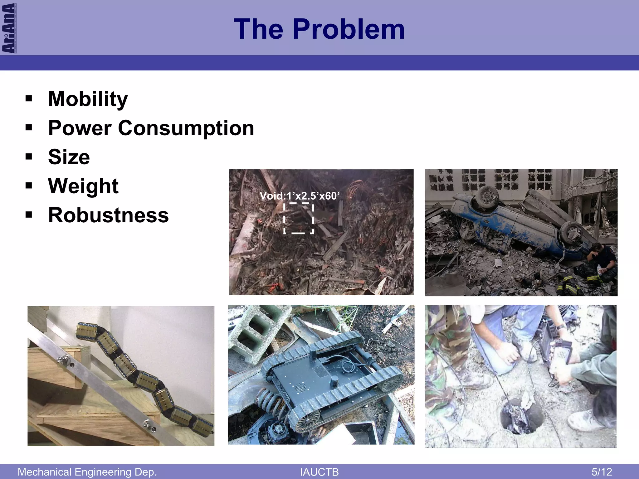


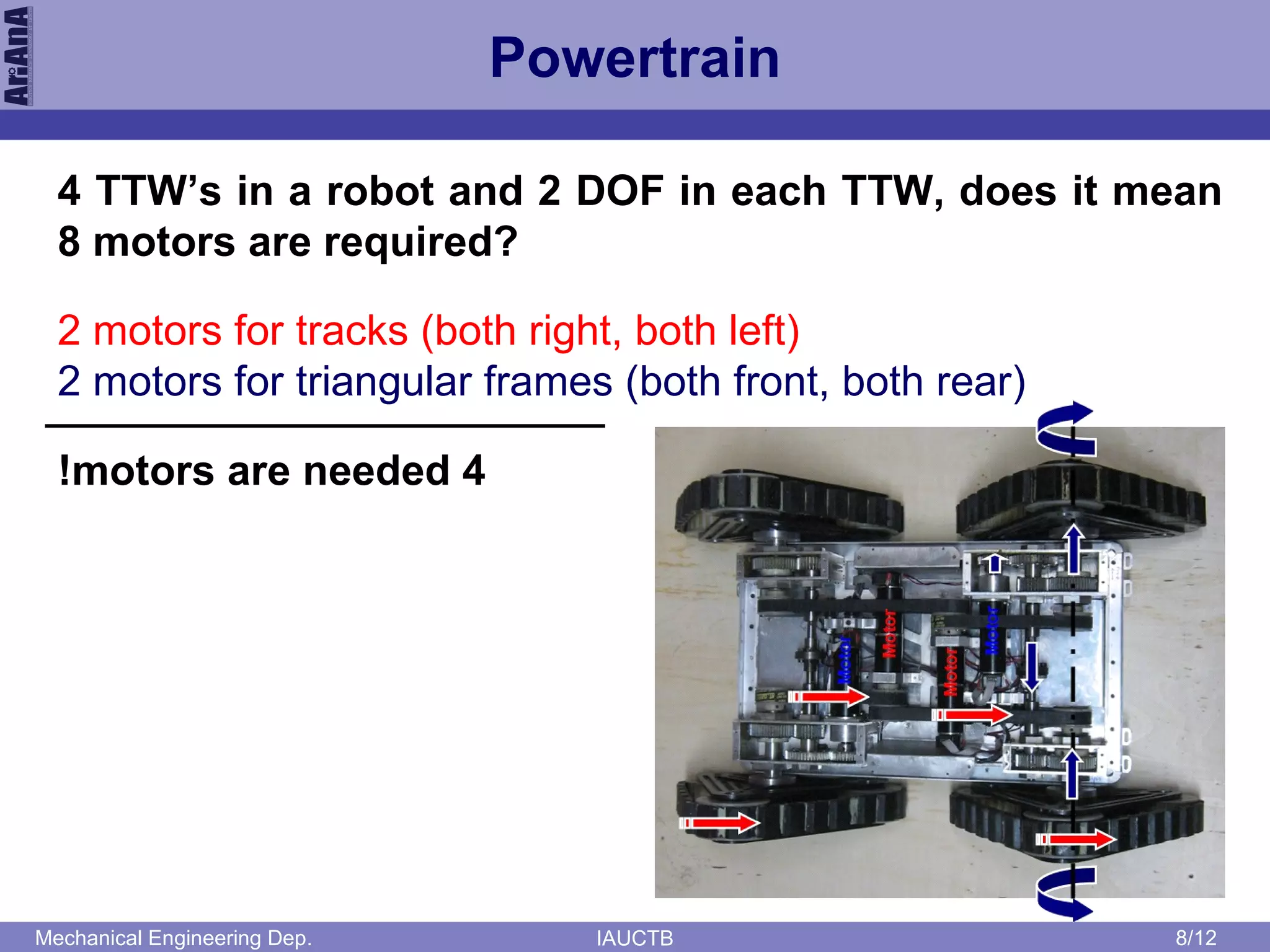


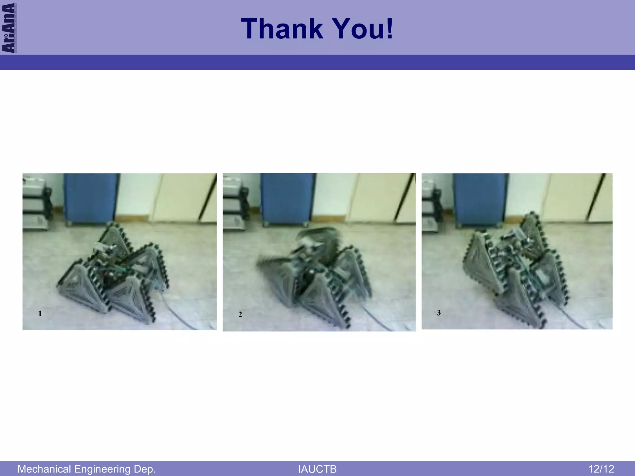

The document presents a new hybrid locomotion mechanism called triangular tracked wheel (TTW) aimed at enhancing mobility for robots in search and rescue applications. It discusses the kinematics, locomotion styles, and power requirements of the TTW system while comparing it to earlier works. The proposed design emphasizes efficiency and adaptability in challenging environments.