Strength 1
•
3 likes•3,522 views

This document contains 9 problems related to calculating stresses in mechanical components and structures. Problem 1 asks to calculate normal stresses in two cylindrical rods welded together. Problem 2 asks to determine minimum diameters for the rods given a stress limit. Problem 3 asks to calculate maximum stresses in links connecting points of a structure. Problem 4 asks to determine the minimum length of cuts in a glued wooden joint given a shear stress limit.

Recommended
More Related Content
What's hot
What's hot (20)
Similar to Strength 1
Similar to Strength 1 (20)
Recently uploaded
Recently uploaded (20)
Strength 1
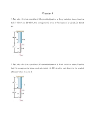
- 1. Chapter 1 1. Two solid cylindrical rods AB and BC are welded together at B and loaded as shown. Knowing that d1=50mm and d2=30mm, find average normal stress at the midsection of (a) rod AB, (b) rod BC. 2. Two solid cylindrical rods AB and BC are welded together at B and loaded as shown. Knowing that the average normal stress must not exceed 140 MPa in either rod, determine the smallest allowable values of d1 and d2
- 2. 3. Each of the four vertical links has an 8 x 36· mm uniform rectangular cross section and each of the four pins has a 16 mm diameter. Determine the maximum value of the average normal stress in the links connecting (a) points B and D, (b) points C and E. 4. Two wooden planks, each 22 mm thick and 160 mm wide, are joined by the glued mortise joint shown. Knowing that the joint will fail when the average shearing stress in the glue reaches 820 kPa, determine the smallest allowable length of the cuts if the joint is to withstand and axial load of magnitude P=7.6 kN.
- 3. 5. Members AB and BC of the truss shown are made of the same alloy. It is known that a 20 mm square bar of the same alloy was tested to failure and that an ultimate load 0f 120 kN was recorded. If a factor of safety of 3.2 is to be achieved for both bars, determine the required cross-sectional area of (a) bar AB, (b) bar AC. 6. A load P is supported as shown by a steel pin that has been inserted in a short wooden member hanging from the ceiling. The ultimate strength of the wood used is 60 MPa in tension and 7.5 MPa in shear, while the ultimate strength of the steel is 145 MPa in shear. Knowing that b=40 mm, a=55 mm and d=12 mm, determine the load P if an overall factor of safety of 3.2 is desired. 28 kN
- 4. 7. For the support of Prob. 6, knowing that the diameter of the pin is d=16 mm and that the magnitude of the load is P=20 kN, determine (a) the factor of safety for the pin, (b) the required value of b and c if the factor of safety for the wooden member is the same as that found in part a for the pin. 8. In the structure shown, an 8 mm diameter pin is used at A, and 12 mm diameter pin are used at B and D. Knowing that the ultimate shearing stress is 100 MPa at all connections and that the ultimate normal stress is 250 MPa in each of two links joining B and D, determine the allowable load P if an overall factor of safety of 3.0 is desired.
- 5. 9. Two wooden member of uniform rectangular cross section are joined by the simple glued scarf splice shown. Knowing that P =11 kN, determine the normal and shearing stress in the glued splice.